
Subscribe to Our Youtube Channel
Related Manuals for X-Rite 891


Summary of Contents for X-Rite 891
- Page 1 891/892 A U T O M A T I C S T R I P R E A D I N G D E N S I T O M E T E R S Operation Manual...
- Page 3 X-Rite 891/892 Auto Strip Reading, Color Photographic Densitometer. This instrument represents the very latest in microcontrollers, integrated circuits, optics, and display technology. As a result, your X-Rite instrument is a rugged and reliable instrument whose performance and design exhibit the qualities of a finely engineered instrument, which is not surpassed.
- Page 5 I N T R O D U C T I O N User Information This equipment has been tested and found to comply with the limits for a Class A digital device, pursuant to Part 15 of the FCC Rules. These limits are designed to provide reasonable protection against harmful interference when the equipment is operated in a commercial environment.
- Page 6 VORSICHT: Betriebs- und Verletzungsgefahr besteht bei Gebrauch von anderen Adaptern als X-Rite SE30-77 (100-240 V). ADVERTENCIA: No use otro cargador de las pilas que no sea la pieza X-Rite SE30-77 (100-240V), por el riesgo de mal funcionamiento del equipo. ATTENTION: Ne pas utiliser d’adaptateur autre que SE30-77 (100-240V) de X-Rite au risque de mauvais fonctionnement de l’appareil.
- Page 7 891, 892 Directive(s) Conformance: EMC 89/336/EEC LVD 73/23/EEC As of August 13, 2005, X-Rite products meet the European Union – Waste Electrical and Electronic Equipment (WEEE) directive. Please refer to www.xrite.com for more information on X-Rite’s compliance with the WEEE directive.
- Page 8 The contents of this manual are the property of X-Rite, Incorporated and are copyrighted. Any reproduction in whole or part is strictly prohibited. Publication of this information does not imply any rights to reproduce or use this manual for any purpose other than installing and operating the equipment described herein.
- Page 9 U S E R I N F O R M A T I O N LIMITED WARRANTY X-Rite, Incorporated warrants each unit manufactured to be free of defects in material and workmanship for a period of twelve months. If the fault has been caused by misuse or abnormal conditions of operation, repairs will be billed at a nominal cost.
- Page 10 I N T R O D U C T I O N...
-
Page 11: Table Of Contents
I N T R O D U C T I O N Table of Contents This manual is organized into eight sections and five appendices. In order to make the best use of your instrument, it is recommended that you read all sections and appendices. - Page 12 I N T R O D U C T I O N SECTION FOUR - Establishing Reference (AIM) Values References Strip Measurement ___________________________4-1 Correction Factor Procedures______________________4-4 Crossover Procedure ____________________________4-5 View Reference Data ____________________________4-6 Aim Value Adjustments (AVA) __________________________4-8 View Aim Values _______________________________4-9 Transmit Reference and Aim Values ______________________4-10 SECTION FIVE - Control Strip Operation Measuring Control Strips _______________________________5-1...
-
Page 13: Unpacking And Inspection
If reshipment is necessary, the instrument should be packaged in the original carton. If the original carton is not available, contact X-Rite to have a replacement shipped to you. Packaging Drawing and Parts List Check your packaging contents against your packing list and your original order. -
Page 14: Product Description
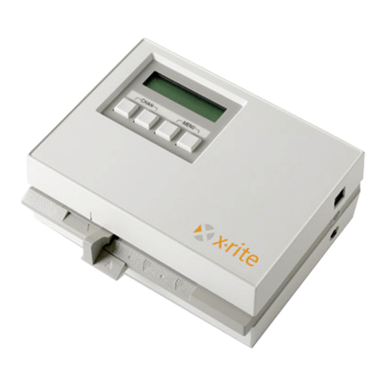
S E C T I O N O N E PRODUCT DESCRIPTION The X-Rite 891/892 automated instruments measures paper, film, and printer balance control strips. Simply insert the strip into the instrument for motorized, automatic measurements. Red, green, and blue density data is sorted for fields such as HD, LD, and Stain, then simultaneously displayed and transmitted to a minilab printer for analysis. -
Page 15: Applying Power
To apply power to the instrument: 1. Verify that the voltage indicated on the adapter complies with the AC line voltage in your area. If not, contact X-Rite or your authorized representative. 2. Insert the small plug from the adapter into the power-input connector on the instrument. -
Page 16: User Interface
- allows configuration and data entry into the internal log buffer. NOTE: The “NET” system configuration option must be turned On for page 6 to appear. The log buffer options are covered in the 891/892 Networking Installation/Operation Manual, P/N 891-503. -
Page 17: Display And Keyswitch Definition
G E T T I N G S T A R T E D Display and Keyswitch Definition The characters in the bottom row of the display dictate which function is selected or which action takes place when a corresponding keyswitch is pressed. -
Page 18: Adjusting The Paper Guides
S E C T I O N O N E ADJUSTING THE PAPER GUIDES To accommodate various size paper strips, the instrument has an adjustable paper guide on each side of the strip entrance. Each paper guide has a pointer (triangle) that is aligned with a number on the guide rail. -
Page 19: Strip Measurement Techniques
G E T T I N G S T A R T E D STRIP MEASUREMENT TECHNIQUES All control strip types should have at least a 30.5mm (1.25”) leader before the first measurable patch. However, strips with less than a 30.5mm leader can also be measured reliably if required. - Page 20 S E C T I O N O N E Single Pass Single pass strips require the strip to be inserted into the instrument once. In this example, the strip—Kodak RA4—can be inserted in either direction. Refer to your Control Strip and Balance Print Format Guide for information on all strips supported.
- Page 21 G E T T I N G S T A R T E D Indicates magenta patches are measured PASS TWO Guide number flashes, indicting strip positioning Indicates yellow patches are measured PASS THREE Guide number flashes, indicting strip positioning The third pass requires the strip to be rotated to take the measurement.
-
Page 22: Film Strip
S E C T I O N O N E Film Strip The Film category requires that the film strip be inserted into the 35mm slot located above the center diamond. In this example—Kodak C41—the strip can be inserted in either direction. Refer to your Control Strip and Balance Print Format Guide for information on all strips supported. -
Page 23: Calibration Information
If your Auto-Cal strip gets ruined or worn, you can order a replacement from X-Rite or your local dealer. Order Part Number 880-100. Frequency of Calibration Under normal operating conditions, the instrument should be calibrated... -
Page 24: Auto Calibration Procedure
2. Insert the designated end of the Auto-Cal strip into the 35mm slot until it comes to rest against the drive rollers. X-RITE Auto-Cal Strip P/N 880-100 Patent Pending SERIAL #: XXX-XXX 35mm slot CAL R= 0.04 G= 0.07 B= 0.08... -
Page 25: Manual Calibration Procedure
2. Using the same densitometer, measure the white area below the first black bar on the X-Rite Auto-Cal strip and record the Red, Green, and Blue values. X-RITE Auto-Cal Strip P/N 880-100 Patent Pending SERIAL #: XXX-XXX CAL R= 0.04 G= 0.07 B= 0.08... - Page 26 Auto-Cal strip into the 35mm slot until it comes to rest against the drive rollers. INSERT CAL STRIP auto MANUAL X-RITE Auto-Cal Strip P/N 880-100 Patent Pending SERIAL #: XXX-XXX 35mm slot CAL R= 0.04 G= 0.07 B= 0.08 INSERT THIS END Note insertion direction •...
-
Page 27: Instrument Configuration
S E C T I O N T H R E E Setting System Configuration The system configuration allows you to customize your instrument to meet your requirements. The configuration should be viewed and edited as needed before any measurements are taken. Section Three Contents •... -
Page 28: Page 2 Configuration Options
S E C T I O N T H R E E Page 2 Configuration Options IO preset This options provides several QC system selections. All the necessary RS-232 interface parameters are automatically set when a predefined I/O preset is selected. A “CUSTOM” preset is available which allows you manually set all available I/O options. -
Page 29: Page 2B Configuration Options
S E T T I N G S Y S T E M C O N F I G U R A T I O N When set to Off (xon), the instrument ignores XON/OFF codes. Note, usage is limited to output at this point. Page 2b Configuration Options DPT (Decimal Point) Controls the decimal point availability during data output. -
Page 30: Configuration Setup Procedure
S E C T I O N T H R E E Configuration Setup Procedure • Options that toggle on and off display in upper-case (on) or lower-case (off). For example, COMP = on and comp = off. • You can save and exit the configuration at anytime without editing all options. - Page 31 S E T T I N G S Y S T E M C O N F I G U R A T I O N • Press key ll or key lll to page through and select a preset options (CUSTOM, REPORT, SPRD-SHT, k:TNetA, etc.).
- Page 32 S E C T I O N T H R E E • After editing Page 2b Configuration options, press key l (P2b) to advance to Page 2c Configuration screen. CNFG SAVE P2c DEL AXMT REF 8. Page 2d Configuration Screen •...
-
Page 33: Date And Time
S E T T I N G S Y S T E M C O N F I G U R A T I O N DATE AND TIME The date and time function allows you to adjust the instruments internal clock. - Page 34 S E C T I O N T H R E E...
-
Page 35: References Strip Measurement
Due to the variability of printer balance strips, correction factors and strip crossover procedures are not available. The 891/892 densitometer can automatically enter correction factors (ACF) for a selected reference strip. This occurs if they are preloaded into the instrument using Kodatel, etc. - Page 36 S E C T I O N F O U R FUNCTION MENU p4 view xmit ref 2. Press key I (pap, etc.) located on Select Ref Chan screen to select reference channel. After selecting channel, press key llll (go>) to advance to the measurement screen.
- Page 37 E S T A B L I S H I N G R E F E R E N C E ( A I M ) V A L U E S • If additional strips are required (maximum of eight), press key llll (yes) and repeat measurement sequence with new reference strip.
-
Page 38: Correction Factor Procedures
S E C T I O N F O U R 9. The instrument display screen indicates that the new reference is entered and allows you to view the data. If you want to view the measurement data, press key llll (yes) and refer to Viewing Reference Data later in this section. -
Page 39: Crossover Procedure
E S T A B L I S H I N G R E F E R E N C E ( A I M ) V A L U E S Crossover Procedure The crossover procedure reduces the affect of change that can occur between old and new batches of reference strips. -
Page 40: View Reference Data
S E C T I O N F O U R 6. The instrument display screen indicates that the new reference is entered and allows you to view the data. If you want to view the measurement data, press key llll (yes) and refer to Viewing Reference Data below. If you do not want to view the data, press key lll (no) to return instrument screen to Channel menu. - Page 41 E S T A B L I S H I N G R E F E R E N C E ( A I M ) V A L U E S displays after pressing key ll (view) if the last strip NOTE: VIEW LAST measured is a different format than the reference previously measured in that...
-
Page 42: Aim Value Adjustments (Ava)
S E C T I O N F O U R AIM VALUE ADJUSTMENTS (AVA) Certain conditions may require value adjustment of your reference strips. The aim value adjustments (AVA) are range limited and will not exceed the aim value adjustment tolerances (AVAT’s) set in the instrument. Simultaneously pressing key lll and key llll labeled MENU at anytime aborts the AVA function. -
Page 43: View Aim Values
E S T A B L I S H I N G R E F E R E N C E ( A I M ) V A L U E S • Press key l (review) to review the aim adjustment fields. Press llll (return) to save adjustments and return to the Editor Menu. - Page 44 S E C T I O N F O U R TRANSMIT REFERENCE AND AIM DATA Strip reference and aim data is available for transmission from the I/O port “A” on the instrument. Individual channels are selected for transmission. Transmitted reference values consist of the average values (if more than one strip was measured) with any correction factors applied.
- Page 45 E S T A B L I S H I N G R E F E R E N C E ( A I M ) V A L U E S 4. Select strip to transmit. • Previously measured reference strips are viewed by pressing key ll (<) to go back in time, or pressing key lll (>) to go forward in time.
- Page 46 S E C T I O N F O U R 4-12...
-
Page 47: Measuring Control Strips
S E C T I O N F I V E Control Strip Operation The values obtained when measuring a control strip are the deviations from the reference values. It is important to make sure control strips and reference strips used are from the same batch number. Always inspect control strips for damage before measuring. - Page 48 S E C T I O N F I V E 1. Select strip channel from Channel Menu page 1, 2, or 3. 2. If format displayed is not correct, press key llll (other) to select correct strip format. READ k:RA—4 ALL AT <18 18>...
-
Page 49: View Control Strip Data
C O N T R O L S T R I P O P E R A T I O N • For Auxilary channels, control limit pass or violation message is momentarily displayed followed by a Load into Channel question. Pressing key lll (no) allows you to view the data without loading it into the database. - Page 50 S E C T I O N F I V E 2. Press key l (D-min) to page through RGB data fields of the strip. 3. Previously measured control strips are viewed by pressing key ll (<) to go back in time, or pressing key lll (>) to go forward in time. 4.
-
Page 51: Manually Transmitting Strip Data
C O N T R O L S T R I P O P E R A T I O N MANUALLY TRANSMITTING STRIP DATA The manual transmission of stored strip data can occur whenever required. Individual strip data (actual values or deviations) or all strips that reside in one channel can be selected for transmission. - Page 52 S E C T I O N F I V E...
-
Page 53: Measuring Internegatives
S E C T I O N S I X Internegative Operation 892 Only) In addition to the 891 instrument functionality, the 892 instrument has the capability of measuring internegative strips. The 892 also computes changes in exposure and filter pack necessary to balance the internegative using the density difference method. - Page 54 S E C T I O N S I X 4. Select internegative film by pressing key ll or key lll (4114). Select 6011 if your are using film similar to Kodak 6011 or interneg film 4112. Select 4114 if you are using film similar to Kodak 4114. READ Ineg Step1 Typ2...
-
Page 55: Viewing Internegative Data
I N T E R N E G A T I V E O P E R A T I O N ( 8 8 2 O N L Y ) VIEWING INTERNEGATIVE DATA The View function allows you to view the density difference values and recommended filter pack changes. -
Page 56: Auto Exposure And Filter Pack Compensation
S E C T I O N S I X NOTE: For “Type 1” internegatives (4 x 5 format), all of the even numbered steps are computed internally using a curve fitting algorithm. Actual internegatives only contain the odd numbered steps. AUTO EXPOSURE AND FILTER PACK COMPENSATION The Auto function initiates the automatic exposure and filter pack compensation. - Page 57 I N T E R N E G A T I V E O P E R A T I O N ( 8 8 2 O N L Y ) 4. The display screen now indicates suggested changes for your filter pack. These numbers are changes (indicated by the Greek letter ∆) and should be added to the filter pack used for exposing this internegative.
- Page 58 S E C T I O N S I X...
- Page 59 S E C T I O N S E V E N Networking The 891 and 892 instruments are networked through an external modem using X-Rite’s QCNetII protocol. Refer to X-Rite 891/892 Networking Installation/Operation Manual for details (Part Number 891-503), or contact your X-Rite representative.
- Page 60 S E C T I O N S E V E N...
-
Page 61: Repair Information
Troubleshooting Tips REPAIR INFORMATION The X-Rite 891/892 is covered by a one-year limited warranty and should be referred to the factory or an authorized service center for repairs within the warranty period. Attempts to make repairs within this time frame may void the warranty. -
Page 62: Cleaning The Instrument
S E C T I O N E I G H T CLEANING THE INSTRUMENT Your instrument requires very little maintenance to achieve years of reliable operation. However, to protect your investment and maintain reading accuracy, a few simple-cleaning procedures should be performed from time to time. -
Page 63: Cleaning The Calibration Strip
S E R V I C E A N D G E N E R A L M A I N T E N A N C E Cleaning the Calibration Strip (Part Number 880-100) The Auto-Cal strip can be cleaned with a mild soap detergent, and wiped dry with a clean, lint-free cloth. -
Page 64: Replacing The Read Lamp
S E C T I O N E I G H T REPLACING THE READ LAMP (PART NUMBER 880-07) NOTICE: New lamp may appear bent, DO NOT attempt to straighten. 1. Remove four screws 1 securing the bottom cover 2 with a phillips-head screwdriver. -
Page 65: Troubleshooting Tips
• Recalibrate instrument. • Clean reflection cal strip or replace if bad. • Replace read lamp.* • Contact X-Rite or Authorized Service Center. Transmission measurement incorrect: • Recalibrate instrument • Replace read lamp* • Contact X-Rite or Authorized Service Center. - Page 66 S E C T I O N E I G H T...
- Page 67 A P P E N D I X A Technical Specifications Transmission Process Control Film Width 35mm fixed slot or 1.4–6.0in. adjustable Measurement Speed 1.1 to 1.4 in/sec (1.2 typical) 891 Spectral Response Status M 892 Spectral Response Status A and M Density Range 0–4.0D Density Accuracy ±.02D (0–3.00D), ±1% (3.01–3.40D)
- Page 68 A P P E N D I X A...
- Page 69 If any error messages listed, or not listed should appear, make a note of it and take the appropriate steps to try to correct it. If an error message is consistently displayed, contact X-Rite or an authorized service center.
- Page 70 A P P E N D I X B Message Reason Possible Cause Solution C-LIMIT EXCEEDED Strip measured Computed values minus Consult the manufacturer’s (during measurement) exceeds Control aims, are greater than processor manual. Limit. the calculated Control limit. S-LIMIT EXCEEDED Strip measured RGB values are not Consult the manufacturer’s...
- Page 71 A P P E N D I X C Term Abbreviations Automatic Line Feed Strip is one pass and may be read in either direction (strip measurement mode) Average aux 1 through aux 6 Auxiliary 1 through Auxiliary 6 Aim Value Adjustments AXMT Automatic Transmit baud...
- Page 72 A P P E N D I X C Normal patch must be read first (strip measurement mode) NUO 1-Pass Normal/Under/Over in 1 pass OLD-1 through OLD-3 Old Strip #1 through Old Strip #3 Paper Printer Balance, Master Channel PIN5 Pin5 of RS232 port can be set to Off, Busy, or CTS p1 through p5 Page #1 through Page #5...
- Page 73 A P P E N D I X D Parts List and Packaging Drawings Parts List...
- Page 74 A P P E N D I X D Packaging Drawing...
- Page 75 A P P E N D I X E Instrument Firmware Update Your instrument’s firmware can be updated from a host computer via a modem, or from a direct connection to a PC serial port. Both methods are discussed on the following pages. MODEM UPDATE INFORMATION Newer versions of Kodak’s Kodatel 2 and Photoware’s Windense quality control software programs (running on a host computer) provide an...
- Page 76 NOTE: Make sure the modem baud is set to "57.6K." Press netwk key on p5 menu. Press cfg key, mod key, and baud key. Edit baud if required. Refer to Section Two in the 891/892 Networking Installation and Operation Manual for additional information.
- Page 77 I N S T R U M E N T F I R M W A R E U P D A T E • Press key lll (snd), Waiting for Host is displayed. NOTE: If "NET is not on . . ." message appears, you must enable networking.
- Page 78 A P P E N D I X E...
- Page 80 FAX 1-888-826-3044 or (00) 420 517-320-331 K.K. Barcelona, Spain 616-534-0686 FAX (00) 420 517-320-335 34 93 567 70 73 Tokyo, Japan International 81-3-5439-5971 FAX 34 93 567 70 78 1-888-826-3039 or FAX 81-3-5439-5972 616-534-7663 FAX 616-534-0723 P/N 891-500 Rev. N...
Need help?
Do you have a question about the 891 and is the answer not in the manual?
Questions and answers