
Related Manuals for X-Rite 310


Summary of Contents for X-Rite 310
- Page 1 Color Transmission Densitometer Operator Manual For 310T Color Transmission Densitometer and 310TR Color Transmission/Reflection Densitometer www.valuetronics.com...
- Page 2 www.valuetronics.com...
- Page 3 X-Rite 310 Transmission/Reflection Densitometer. This instrument represents the very latest in microprocessors, integrated circuits, and display technology. As a result, your 310 is a rugged and reliable instrument whose performance and design exhibit the qualities of a finely engineered laboratory instrument.
- Page 4 Model No.: Directive(s) Conformance: EMC 89/336/EEC LVD 73/23/EEC As of August 13, 2005, X-Rite products meet the European Union – Waste Electrical and Electronic Equipment (WEEE) directive. Please refer to www.xrite.com for more information on X-Rite’s compliance with the WEEE directive.
-
Page 5: Limited Warranty
An Instrument Registration Card is enclosed with each instrument. The purchaser should fill in the card completely and return it to X-Rite postmarked no later than 10 days form the date of receipt. This card registers your instrument with us for warranty coverage. -
Page 6: Table Of Contents
TABLE OF CONTENTS Getting Started Introducing the X-Rite 310 ..........1-2 Unpacking Instructions............1-3 Instrument Vocabulary ............1-4 Setup and Power..............1-5 Instrument Specifications ............ 1-6 Using the 310 Definitions of Terms ............2-2 Keyboard Vocabulary............2-3 Reading Heads ..............2-6 Display Panel Vocabulary ........... -
Page 7: Getting Started
Getting Started This chapter contains the introductory information and setup procedures you’ll need to get your 310 powered up and ready to use. Chapter Contents Introducing the X-Rite 310 ..........1-2 Unpacking Instructions............1-3 Instrument Vocabulary ............1-4 Setup and Power..............1-5 Instrument Specifications ............ -
Page 8: Introducing The X-Rite 310
X-Rite 310 Operator Manual INTRODUCING THE X-RITE 310 When we designed the 310, we took a close look at the needs of the photofinishing industry. Then, we applied years of experience in densitometry to develop this sophisticated color transmission/reflection densitometer. -
Page 9: Unpacking Instructions
X-Rite, Incorporated, use the original carton. If the original carton is not available, X-Rite can ship a replacement to you. A padded carrying case for your 310 is available from X-Rite. It provides the safest possible storage for your instrument, and also makes it easily portable. -
Page 10: Instrument Vocabulary
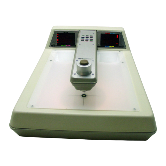
Aperture Keyboard The 310 Transmission Densitometer The 310 Transmission Densitometer provides a Light Table platform for backlighting transmissive measurement targets such as film and transparencies. The Reading Head Arm that extends over the Light Table features the Keyboard and the Reading Head. -
Page 11: Setup And Power
You can select an aperture (measuring area) of 1mm, 2mm, or 3mm. All three sizes are supplied with your 310. If you are unsure which size is best for your application, use the 3mm aperture; it provides the best results for averaging film measurements. -
Page 12: Instrument Specifications
X-Rite 310 Operator Manual INSTRUMENT SPECIFICATIONS Reflection Specifications Conforms to ANSI PH 2.17 Response: Visual:..........X-Rite Visual Red (Cyan): ........Status A Green (Magenta): ......Status A Blue (Yellow) ........Status A Measuring Range:........0.0D - 2.5D Accuracy:..........±.02D from 0-2.5D Repeatability: .......... - Page 13 Then, a vocabulary overview of the instrument keyboards, reading heads, and displays is provided. Next, this chapter covers the 310’s main features and functions, including Calibration; Null procedures; and Density, Range, and Color Balance measurement.
-
Page 14: Definitions Of Terms
This is useful in determining the plus/minus variation of the measured range as compared to a standard. Status A/M (Transmission only.) The 310 can be set at Status A response or Status M response. By simply pressing a keyand without mechanically changing opticsStatus can be switched between the two. -
Page 15: Keyboard Vocabulary
Using the 310 KEYBOARD VOCABULARY Your 310’s functions are controlled via the Keyboard on the Reading Head Arm. The Reflection Head Assembly (Model 310TR only) also has a Keyboard. Each has twelve keys: The 310 Transmission Densitometer Keyboard has three rows of four keys; the Reflection Head Assembly has four rows of three keys. - Page 16 X-Rite 310 Operator Manual 310 Transmission Densitometer Keyboard Key Pressed Function F (Function)..Toggles key functions between those listed above the keys to those listed below the keys. DIF (Difference) ..Indicates the difference between a stored reference value and a new measurement.
- Page 17 Using the 310 Reflection Head Assembly Keyboard Key Pressed Function F (Function)..Toggles key functions between those listed above the keys to those listed below the keys. DIF (Difference) ..Indicates the difference between a stored reference value and a new measurement.
-
Page 18: Reading Heads
X-Rite 310 Operator Manual READING HEADS The instrument Keyboards are used to activate measurement functions and enter measurement values; however, actual measurements are performed using the Reading Head and Read Button on the Reading Head Arm; and the Reflection Head on the Reflection Head Assembly. -
Page 19: Display Panel Vocabulary
Using the 310 DISPLAY PANEL VOCABULARY Function and measurement information for both the 310 Transmission Densitometer and the Reflection Head Assembly is displayed in the Left and Right Display Panels on the 310. Along the outside edge of each display panel, functions related to the Keyboard keys are listed. -
Page 20: Checking Status (Transmission Only)
The first thing you should do before performing a measurement or a calibration is to check your Status response setting. Status responses are industry standards for densitometric measurements. Your 310 allows two response settings: Status A, which defines the response function for the measurement of... -
Page 21: Calibrating The 310
Using the 310 CALIBRATING THE 310 Your X-Rite 310 is designed for long life and extremely stable readings. To maintain proper quality control procedures, you should calibrate your instrument. Once your instrument is calibrated, you should then periodically check calibration to verify measurement accuracy and proper operation of the unit. - Page 22 X-Rite 310 Operator Manual NOTE: It is possible to set Cal Lo on a density higher than 0.00D by entering the appropriate calibration number as shown in Step 4. This is required only for specialized calibrations. 6. Once the desired value appears, press CAL-SET.
- Page 23 “Cal Hi” measurement. The values listed for the check plaque are measurements traceable to certified reference standards maintained at X-Rite, Incorporated. NOTE: Make sure your check plaque is free of smudge marks and dust, which can dramatically affect measurement of the darker steps.
-
Page 24: Quick Zero
X-Rite 310 Operator Manual 8. The Display Panel displays the Cal Hi density value for Cyan (or the first color selected), and the Keyboard is automatically set in numeric format. As necessary, enter the Cal Hi density for Cyan, using a four- digit value. -
Page 25: Nulling (Zeroing) On A Standard
Using the 310 NULLING (ZEROING) ON A STANDARD Before taking measurements, you should “null” or “zero” your instrument. This establishes the “zero” measurement according to which measurements that follow will be calculated. You can null by measuring a standard; or by manually entering the desired standard values. - Page 26 X-Rite 310 Operator Manual To zero on a standard for the multicolor method: 1. Check Status A/M (transmission only). 2. Select the desired mode. Press DEN for Density mode; or F, then Dx10 for D x 10 mode; or BAL for Color Balance mode.
- Page 27 Using the 310 To manually enter a standard for the multicolor method: 1. Check Status A/M (transmission only). 2. Select the desired mode. Press DEN for Density mode; or F, then Dx10 for D x 10 mode; or BAL for Color Balance mode; or RANGE.
-
Page 28: Measuring Density
X-Rite 310 Operator Manual MEASURING DENSITY There are two ways to measure density using the 310: You can take an absolute density measurement that is computed using the values derived from measuring the calibration reference; or you can take a density difference measurement that is computed by subtracting a standard (null) measurement from the density measurement. - Page 29 Using the 310 for reflection, center the sample under the Target Window, then lower the Reflection Head down onto the Target Window. The Display turns off momentarily. When the Display turns back on, release the Reflection Head. The measurement values displayed are now stored in memory until its memory position is updated.
- Page 30 X-Rite 310 Operator Manual To measure absolute density using the multicolor method: 1. Check Status A/M (transmission only). 2. Select transmission or reflection by pressing either DEN (transmission) on the Reading Head Arm Keyboard; or DEN (reflection) on the Reflection Head Keyboard. L.E.D. indicators appear next to DEN on the Left Display Panel;...
- Page 31 Using the 310 To measure absolute density using the auto color method: 1. Check Status A/M (transmission only). 2. Select transmission or reflection by pressing either DEN (transmission) on the Reading Head Arm Keyboard; or DEN (reflection) on the Reflection Head Keyboard. L.E.D. indicators appear next to DEN on the Left Display Panel;...
-
Page 32: Measuring Density X 10
Left Display Panel. Once the D x 10 function is activated in this step, all procedures that follow are the same. MEASURING RANGE (MINIMUM/MAXIMUM) In addition to normal density measurements, your 310 also provides Range and Minimum/Maximum measurement features. There are two ways to measure range using your 310:... - Page 33 Using the 310 6. Measure the second target sample in your series. Hold the measurement (the Read Button or Reflection Head down) until the display turns back on. The difference range value between these two measurements is displayed. Since these are the only two measurements so far, they are the Minimum and Maximum.
-
Page 34: Measuring Color Balance
X-Rite 310 Operator Manual MEASURING COLOR BALANCE In addition to normal density measurements, your 310 also provides Color Balance measurement features. There are two ways to measure color balance using your 310: You can take an absolute color balance measurement that express the density of each color as the difference between the color and the highest of the three primary color densities. - Page 35 Using the 310 The display for the color with the highest measured density is set to 0.00. The other two color displays show the additional density required for these colors to “balance” with the high-density color to achieve a neutral gray color. The VIS display contains the greatest density value computed, which may be used to help adjust exposure time or illumination intensity.
-
Page 36: Using Memory
X-Rite 310 Operator Manual USING MEMORY Your X-Rite 310 comes equipped with five display memory locations labeled M1 through M5for Status A Transmission, five Status M Transmission, and five for Status A Reflection. Density, Density x 10, and Balance each have five display memory locations for Status A Transmission, Status M Transmission, and Status A Reflection. -
Page 37: Displaying And Setting Time And Date
March 16, 1995, the Display reads 03. 16 95. The time and date settings are maintained in the 310 even after it has been turned off or unplugged and the turned back on after a long period of time. -
Page 38: Using Mode Functions
08 and 09.....Not used. If 09 is entered, the display shows #.#=n. To exit this mode, press CAL-SET. 10......Activates output for optional X-Rite 20 Column Printer P/N 309-13 (used in conjunction with mode function 18 or 19). Also, deactivates mode function 21. - Page 39 A carriage return line feed (LF) is transmitted after the last color. NOTE: Your 310 is shipped with the following modes selected: 02, 04, 07, 11, 12, 14, and 18. 2-27 www.valuetronics.com...
-
Page 40: Troubleshooting
310 power off and then back on. Some problems can occur if the 310 is not operated properly. Below are some of these problems and their possible solutions. -
Page 41: Input/Output Functions
Input/Output Functions Your X-Rite 310 is equipped with a port that allows information to be transmitted from the densitometer to another device, such as a printer or a computer. This chapter covers the different functions you can perform using your densitometer with these other devices. -
Page 42: Using The Input/Output (I/O) Port
TECHNET®) via a standard RS232 Interface (P/N 319-83). Connect one end of the cable assembly to the 25-circuit D type connector on the back of the 310. Connect the other end of the cable to the computer as designated by the computer manufacturer’s documentation. -
Page 43: Serial Output Formats
Input/Output (I/O) Functions SERIAL OUTPUT FORMATS The X-Rite 310 has four different output formats. The first two formats are designed for a matrix printer or sophisticated computer interface. The third format is the format specified by Kodak for their TECHNET system. - Page 44 The printer format baud rate is dictated by the external device that the 310 is connected to. The 310 can be selected for a 300 or 1200 baud rate. Refer to “Using Mode Functions” in Chapter 2 for information on selecting baud rate.
- Page 45 Clear-to-Send goes high before continuing. If Clear-to-Send is low when a PRINT command is given, the 310 will wait until the Clear- to-Send goes high.
- Page 46 Cyan (Red) Magenta (Green) Yellow (Blue) The 310 is also capable of outputting data in this format while in the DENSITY x 10 function. The four density characters are output MSD to LSD. The Clear-to-Send/Busy pin is used as a Clear-to-Send for this format. In other words, if the Clear-to-Send is at a logic one (high) the densitometer will output data.
-
Page 47: Serial Input Format
Input/Output (I/O) Functions SERIAL INPUT FORMAT Your 310 is equipped with an input that allows the 310 to be controlled or monitored remotely. Every function that can be performed at the keyboard plus a few functions not activated by the keyboardcan be activated via the serial input. - Page 48 X-Rite 310 Operator Manual 4. “LF” is an ASCII “Line Feed” that is used as a delimiter and tells the densitometer to perform the preceding command. Unless that command was “G,” it waits for the next command. NOTE: a “carriage return” (CR) can be sent instead of an “LF” if necessary.
- Page 49 Input/Output (I/O) Functions Address and Modifier Format The following is a list of the addresses and the keys or control registers at each of those addresses. Address Keys or Control Registers Tone Timer Color Blue (Yellow) Digit 4 Blue (Yellow) Digit 3 Blue (Yellow) Digit 2 Blue (Yellow) Digit 1 Green (Magenta) Digit 4...
- Page 50 X-Rite 310 Operator Manual The following is a list of the modifiers to be used with various keys or control registers. Keys or Modifier Control Register Remarks 01 thru FF Tone Timer Least significant bit= 10ms of tone Color To be used if more than one color on at a time is needed.
- Page 51 Input/Output (I/O) Functions Remote Control Switches and Selects (“1”, “2”, “3”, “4”, or “5” is the Action Code and its prefix of “ON,” “OFF,” “0”, “1”, or “2” is used instead of an ADDRESS and MODIFIER.) Read + Light Source Turns on Light Source and forces a “READ”...
- Page 52 X-Rite 310 Operator Manual Serial Input Notes Additionally, the following is required in order to use the serial input: 1. The baud rate of the serial input must be the same as the densitometer uses for serial output. 2. Data shall be transmitted with one start bit (logic 0) and one or two stop bits (logic 1) added to the data (7 bits of ASCII).
-
Page 53: General
X-Rite will repair any 310 submitted past warranty. Shipping costs to the factory or authorized repair station shall be paid by the customer, and the instrument shall be submitted in its special carton as a complete, unaltered unit. -
Page 54: Lamp And Bulb Replacement
Replacement IMPORANT: Disconnect the line cord from power receptacle before replacing bulb. A spare Halogen Lamp Assembly (P/N 310-60) is provided for the Transmission Densitometer. Should the lamp fail, replace as follows: 1. Disconnect line cord. 2. Set unit upside down and remove the larger bottom cover by removing the three screws located in the front portion of the cover. - Page 55 Maintenance Reflection Tungsten Halogen Lamp Replacement A spare reflection halogen lamp assembly is included with the Reflection Head for models 310TR. Should the lamp fail, replace as follows: 1. Remove the top cover from the Reflection Head by removing the four Phillips head screws from the nameplate.
-
Page 56: Cleaning Optics
Assembly. Brush away the dust with a camel hair brush and re-fasten the nose with the three screws. FUSE REPLACEMENT To replace the fuse, locate the fuseholder at the rear of the 310 and replace as follows: 1. Remove the fuseholder cap by pushing it in, rotating counter- clockwise, then pulling the cap off. -
Page 57: Index
Measuring Density x 10, 2-20 Absolute Density, 2-2 Measuring Range Absolute Range, 2-2 (Minimum/Maximum), 2-20 Auto Color, 2-2 Memory, 2-2, 2-24 Mode Functions, 2-26 Calibrating the 310, 2-9 Reflection Density Calibration, Nulling, 2-13 2-11 by Manually Entering a Transmission Density Standard, 2-14 Calbration, 2-9... - Page 58 X-Rite 310 Operator Manual TECHNET Format, 3-5 Turning On Power, 1-5 Time and Date, 2-25 Troubleshooting, 2-27 Unpacking Instructions, 1-3 www.valuetronics.com...
- Page 59 www.valuetronics.com...
- Page 60 Shanghai, PR China (39) 02-967-34266 (49) 2203-91450 (852) 2-568-6283 FAX (39) 02-967-30681 FAX (49) 2203-914519 86-21-6427-2426 FAX (852) 2-885-8610 Vyskov, Czech Republic FAX 86-21-6427-5816 K.K. (00) 420 517-320-331 FAX (00) 420 517-320-335 Tokyo, Japan 81-3-5439-5971 FAX 81-3-5439-5972 P/N 310-42 Rev. CC www.valuetronics.com...
Need help?
Do you have a question about the 310 and is the answer not in the manual?
Questions and answers