
Related Manuals for Tenma 72-2650


Summary of Contents for Tenma 72-2650
- Page 1 72-2650 72-8705A 72-8710A 72-8225A 72-10510 P/N: 110401105556X REV.0 DATE:2016-02-20...
- Page 2 If you have read through the manual, it is recommended that you keep it safe along with the instrument, or in a place where it is easily accessible, should you require the information for future usages.
- Page 3 72-2650/72-10510/72-8225A /72-8705A/72-8710A user manual...
- Page 4 72-2650/72-10510/72-8225A /72-8705A/72-8710A user manual General Safety Overview In order to avoid electric shock, the ground connection The instrument is designed and manufactured under must not be circumvented. Prior to connecting the the safety requirement for GB4793 electric measuring input or output terminal of the product, ensure the instrument and IEC61010-1 safety standards.
- Page 5 72-2650/72-10510/72-8225A /72-8705A/72-8710A user manual Hazard: Indicates there is direct damage hazard close Do not operate the product if it is suspected to to the marking. be malfunctioning: Seek qualified maintenance Warning: Indicates there is potential damage hazard personnel for inspection.
- Page 6 72-2650/72-10510/72-8225A /72-8705A/72-8710A user manual Preface The Manual introduces information related to the operation of digital storage oscilloscopes 72-2650/72-10510/ 72-8225A /72-8705A/72-8710A. The manual comprises the following chapters: Chapter I Introduction Chapter II Instrument Setting Chapter III System Message Example and Troubleshooting...
- Page 7 72-8705A/72-8710A:800x400 gear position settings. ● Support plug and play USB storage equipment and Apart from easy to use,72-2650/72-10510/72-8225A/ be capable of communicating with computer via USB 72-8705A/72-8710A DSO also has high performance storage equipment.
- Page 8 72-2650/72-10510/72-8225A /72-8705A/72-8710A user manual ● Multi-waveform mathematical operation function (including: addition, subtraction, multiplication and division). ● Edge, video, pulse width, alternating trigger and other functions . ● Multi-language menu selection. ● Simplified Chinese and English help information display. Accessories of 72-2650/72-10510/72-8225A/72-8705A/ 72-8710A DSO ● Two of probes with 1:1/10:1 X selection.
-
Page 9: Table Of Contents
72-2650/72-10510/72-8225A /72-8705A/72-8710A user manual Chapter I Introductions ------------------------------------------------------------------------------------------------------------------ 1 1.1 Get to know the User Interface ----------------------------------------------------------------------------------------------------- 1 1.2 General Inspection --------------------------------------------------------------------------------------------------------------------- 5 1.3 Function Inspection -------------------------------------------------------------------------------------------------------------------- 5 1.4 Probe Compensation ------------------------------------------------------------------------------------------------------------------ 7 1.5 Automatic Settings of Waveform Display ----------------------------------------------------------------------------------------- 8 1.6 Introduction to The Vertical System ------------------------------------------------------------------------------------------------ 9... - Page 10 2.9 Set The Cursor Measurement ----------------------------------------------------------------------------------------------------- 46 Chapter III System Message Example and Troubleshooting -------------------------------------------------------------- 47 Chapter IV Technical Information --------------------------------------------------------------------------------------------------- 50 Appendix A: Technical Specification ---------------------------------------------------------------------------------------------- 50 Appendix B: Accessories of 72-2650/72-10510/72-8225A /72-8705A/72-8710A DSO ------------------------------ 68 Appendix C: Maintenance and Cleaning Maintenance ---------------------------------------------------------------------- 68...
-
Page 11: Chapter I Introductions
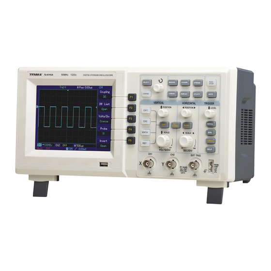
72-2650/72-10510/72-8225A /72-8705A/72-8710A user manual Chapter I Introductions 72-8710A DSO is important for use and the operation of the DSO. The user interface of 72-2650/72-10510/ 72-2650/72-10510/72-8225A /72-8705A/72-8710A 72-8225A /72-8705A/72-8710A DSO consist of: DSO is desk type DSO. It is designed with conventional ● Vertical control... - Page 12 72-2650/72-10510/72-8225A /72-8705A/72-8710A user manual 72-2650 Figure 1-1: 72-2650 DSO Panel Diagram - 5.7-inch TFT color LCD display...
- Page 13 72-2650/72-10510/72-8225A /72-8705A/72-8710A user manual 72-10510 Figure 1-2: 72-10510/72-8225A/72-8705A/72-8710A DSO Panel Diagram -7-inch TFT color LCD display...
- Page 14 72-2650/72-10510/72-8225A /72-8705A/72-8710A user manual DSO User Interface Menu Display (72-10510 pictured)
-
Page 15: General Inspection
30min, and then press F1 auto calibration. At the next abnormal operation or failure to pass the performance menu level, press the F1 button again at the “factory settings” tests, please contact the Tenma product distributors or as shown in Figure 1-4. - Page 16 72-2650/72-10510/72-8225A /72-8705A/72-8710A user manual 72-10510 Warning: please confirm that the DSO has been safely grounded to avoid hazard. DSO accessing to signal Figure 1-5 Setting of Probe Attenuation Rate Switch ①. 72-2650/72-10510/72-8225A /72-8705A/72-8710A ②. It is necessary to set probe attenuation coefficient on DSO.
-
Page 17: Probe Compensation
72-2650/72-10510/72-8225A /72-8705A/72-8710A user manual Press F4 to make the menu display 10× function key to close CH1; press CH2 function key to turn on CH2; repeat step 2 and step 3. Figure 1-6 Setting of attenuation coefficient on DSO Figure 1-7 Probe Compensation Signal 1.4 Probe Compensation... -
Page 18: Automatic Settings Of Waveform Display
72-2650/72-10510/72-8225A /72-8705A/72-8710A user manual steps: 1. Set the probe menu attenuation coefficient as 10×, place the switch on the probe at 10× and connect the DSO Figure1-8b:Correct compensation probe with CH1. Connect the probe end and signal output connector to the probe compensator, the ground... -
Page 19: Introduction To The Vertical System
(For 72-10510/72-8225A/72-8705A/72-8710A DSO). control panel (Left) Attention: 72-10510/72-8225A To disable the input channel for the 72-2650 DSO, /72-8705A/72-8710 A please press the [OFF] button on the vertical system. vertical control panel All of the other vertical system settings will be... -
Page 20: Introduction To The Horizontal System
72-2650/72-10510/72-8225A /72-8705A/72-8710A user manual SCALE knob to change the "s/div" time base gear 1.7 Introduction to The Horizontal System position, and you can find that corresponding changes As shown in the figure below, there is one key and have taken place in the time base gear position display two knobs within the horizontal control area. -
Page 21: Introduction To The Trigger System
72-2650/72-10510/72-8225A /72-8705A/72-8710A user manual All of the other horizontal system settings are explained All of the other trigger system settings are explained in in greater detail in chapter II of this user manual. more detail in chapter II of this user manual. -
Page 22: Chapter Ii Instrument Settings
I if you are still not familiar with the basic control of the operations. 2.1 Set The Vertical System In this chapte r, you will be learning about different Each channel for 72-2650/72-10510/72-8225A / settings related to the 72-2650/72-10510/72-8225A / 72-8705A/72-8710A DSO can be set independently 72-8705A/72-8710A DSO: 2.1 Set The Vertical System through the vertical system menu. - Page 23 72-2650/72-10510/72-8225A /72-8705A/72-8710A user manual Setting coupling channel Pass through DC and AC Coupling The following example shows how to change the coupling components of input signal. of the input channel. If the measured signal connected to the Grounding Disconnect input signal.
- Page 24 72-2650/72-10510/72-8225A /72-8705A/72-8710A user manual channel circuit.) the CH1 channel as shown in the figure below. Figure 2-3 Simultaneous Blocking of Signal DC and AC Components Figure 2-2 Simultaneous Display of Signal DC and AC Setting channel bandwidth Limited Components The following example shows how to change the...
- Page 25 72-2650/72-10510/72-8225A /72-8705A/72-8710A user manual the figure below. Figure 2-5 Waveform Display When Setting Bandwidth Throttling as ON Setting probe Rate Figure 2-4 Waveform Display When Setting In order to function with the attenuation coefficient Bandwidth Throttling in OFF Position setting of probe, it is required to set the probe attenuation coefficient in the channel function menu.
- Page 26 72-2650/72-10510/72-8225A /72-8705A/72-8710A user manual probe coefficient for the input channel as shown in Fine adjustments refer to changing the deflection factor the figure below. with smaller stepping within the current vertical gear position range. Figure 2-6 Probe Attenuation Coefficient Figure 2-7 Coarse and Fine Adjustment of...
- Page 27 72-2650/72-10510/72-8225A /72-8705A/72-8710A user manual waveform and Figure 2-9 for an inverted waveform. Mathematical operation function 72-2650/72-10510/72-8225A /72-8705A/72-8710A DSO support mathematical operation function for the input signals. Figure below show the match result for CH1 + CH2 as an example. Figure 2-8 Vertical Channel Inverted...
- Page 28 72-2650/72-10510/72-8225A /72-8705A/72-8710A user manual Table 2-2: Math Menu ● Measure harmonic content and distortion in the system. ● Display noise characteristic in DC power supply. Function Menu Settings Description ● Analyse vibration. Type Math Mathematic operation Table 2-3: FFT Menu Description...
- Page 29 72-2650/72-10510/72-8225A /72-8705A/72-8710A user manual interruption shall occur at the joints. In frequency domain, FFT operation skills this effect is called leakage. Therefore, in order to avoid Signal with DC component or deflection will lead to the generation of leakage, by multiplying original waveform error or deviation of FFT waveform component.
- Page 30 Hamming window is after transient state or short Hamming slightly superior to pulse, are of large difference. pressing the REF button on the 72-2650 DSO. For Hanning window. 72-10510/72-8225A/72-8705A/72-8710A, pressing the Mainly used for single The best amplitude STORAGE button will load the pre-saved waveform.
- Page 31 72-2650/72-10510/72-8225A /72-8705A/72-8710A user manual If there is no waveform stored at the selected memory Select to load a pre-saved waveform location, you will see a system message showing “no from the internal memory of the DSO Select to load a pre-saved waveform data in the position”.
- Page 32 72-2650/72-10510/72-8225A /72-8705A/72-8710A user manual to expansion or contraction of the waveforms relative to the The horizontal scale control knob is used to change screen centre. When the horizontal position changes, the the time base of the channel waveform, by shown as s/div.
- Page 33 72-2650/72-10510/72-8225A /72-8705A/72-8710A user manual The Window extension time base function is used to moved left and right by turning the horizontal POSITION observe the waveform detail for a given window of the knob or can be enlarged and reduced by turning the waveform.
-
Page 34: Set The Trigger System
TRIG MENU for 72-10510/72-8225A/ 72-8705A/72-8710A and [MENU] for 72-2650. For the 72-10510/72-8225A/72-8705A/72-8710A DSO, it can set the trigger level to be at 50% of signal vertical midpoint by the 50% button. For the 72-10510/72-8225A DSO, it is achieved by pressing SET TO ZERO key. - Page 35 [F1] button at the [TRIG MENU] for the 72-10510/ signal source 72-8225A/72-8705A/72-8710A DSO, by pressing [F1] Set CH2 as the triggering signal source button at the [MENU] for the 72-2650 DSO; Alternating trigger: applicable to trigger signals without Set external trigger input channel as the triggering frequency correlation.
- Page 36 72-2650/72-10510/72-8225A /72-8705A/72-8710A user manual Set trigger on the signal Rising Reject high-frequency rising edge High-frequency components of the triggering Set trigger on the signal Falling Slope (F3) rejection signal (over 80kHz signals) Trigger coupling (F5) falling edge Set trigger on the signal both...
- Page 37 72-2650/72-10510/72-8225A /72-8705A/72-8710A user manual Set external trigger source Set the positive pulse width (divided by 5) as trigger level as trigger signal. EXT/5 Type range (Only for 72-2650) Pulse width Set the negative pulse width as trigger signal. Set AC power line as trigger...
- Page 38 72-2650/72-10510/72-8225A /72-8705A/72-8710A user manual Block the DC component of Table 2-9 Video Trigger Setting the triggering signal Function Menu Settings Description Pass through DC and AC Type Video components of triggering Set CH1 as the triggering signal Trigger signal source...
- Page 39 72-2650/72-10510/72-8225A /72-8705A/72-8710A user manual Figure 2-14 is an example screen display when PAL video trigger model is selected as standard and synchronization mode is All Line Synchronization. Figure 2-15 Video Trigger: Field Synchronization Alternating trigger During alternating trigger, the trigger signal comes Figure 2-14 Video Trigger: Line Synchronization from two input channels, CH1 and CH2 alternatingly.
- Page 40 72-2650/72-10510/72-8225A /72-8705A/72-8710A user manual Force trigger Force trigger can be understood as forcing the DSO to refresh the data acquisition process, so the user can observe the waveform being captured. To enable the force trigger, press the FORCE button. One of the very useful applications for force trigger is at the “normal”...
-
Page 41: Set The Acquire System
72-2650/72-10510/72-8225A /72-8705A/72-8710A user manual “EXT TRIG” input channel. Ex ternal trigger signal Attention: when scanning, the waveform is set as 50ms/div or slower time base, no trigger signal is allowed under “auto connects to “EXT TRIG” input terminal is used for EXT trigger”... - Page 42 The Table 2-11 Acquire Menu example below is a noise waveform acquired by different Function Settings Description acquisition setting of the 72-2650/72-10510/72-8225A / Menu 72-8705A/72-8710A DSO. Sampling Set to sampling acquisition mode.
- Page 43 72-2650/72-10510/72-8225A /72-8705A/72-8710A user manual Notice: 1. Select real-time sampling mode when observing single signal. 2. Select equivalent sampling mode when observing high frequency periodic signal. 3. Select peak detection mode when hoping to observe the signal envelope for any modulation signal.
-
Page 44: Set The Display System
Function The user can change the display setting of the DSO by Settings Description Menu pressing the DISPLAY button of the 72-2650/72-10510/ Vector Display as vector of sampled data points 72-8225A /72-8705A/72-8710A DSO as the figure shows below. Types (F1) -
Page 45: Set The Storage And Load System
72-2650/72-10510/72-8225A /72-8705A/72-8710A user manual XY Mode 2.6 Set The Storage and Load System The user can enter the X-Y mode by pressing the The user can enter the storage and load menu by Display button and select F2. In this mode, CH1 pressing the STORAGE button. - Page 46 72-2650/72-10510/72-8225A /72-8705A/72-8710A user manual Press the Storage button and you will see the Use the multi-purpose knob to select the storage memory following menu: destination. Press F4 to store the waveform. Table 2-13 Waveform Storage Menu Attention: Function Settings Description...
- Page 47 72-2650/72-10510/72-8225A /72-8705A/72-8710A user manual Table 2-14 Waveform Storage Menu (Page 1) Table 2-14 Waveform Storage Menu (Page 2) Function Function Settings Description Settings Description Menu Menu Select to store an acquired waveform Type (F1) Wave Select to store an acquired waveform...
- Page 48 72-2650/72-10510/72-8225A /72-8705A/72-8710A user manual Press F4 to store the waveform Table 2-15 Waveform Storage Menu (Page 1) Function Remove the USB stick. Settings Description Menu Attention: Wave Select to store an acquired waveform Any storage of the waveform will overwrite previous...
- Page 49 72-2650/72-10510/72-8225A /72-8705A/72-8710A user manual memory location. From the DSO setting storage menu (Page 1) Press F4 to store the DSO setting Use the multi-purpose knob to select the storage memory Attention: location. Any storage of the DSO setting will overwrite previous Press F4 to load the pre-stored DSO setting.
- Page 50 72-2650/72-10510/72-8225A /72-8705A/72-8710A user manual Table 2-16 Bit Map File Storage Menu (Page 2) Select to store a Bit Map file into Bit Map Types (F1) Function the USB disk only Settings Description Menu Select waveforms from CH1 channel Select to store a Bit Map file into...
-
Page 51: Set The Utility System
72-2650/72-10510/72-8225A /72-8705A/72-8710A user manual 2.7 Set The Utility System Table 2-17 Utility menu page 1 By pressing the UTILITY function button on the menu Function Settings Description Menu area, the user can set a different utility setting, where the Press to execute self- calibration button locations are shown in the figure below. - Page 52 Select from 1-200 memory location. (F3) Press F3 to save. Load the waveform recording into USB memory. Load (@) The waveform recorder function at the 72-2650/72-10510/ Select from 1-200 memory location. (F4) Press F3 to load. 72-8225A /72-8705A/72-8710A DSO is generally easy to operate.
- Page 53 Go back to previous menu Return (F4) Source (F2) Select RefA as the detection signal RefA One of the very useful functions for the 72-2650/ source Select RefB as the detection signal 72-10510/72-8225A /72-8705A/72-8710A DSO is the RefB source pass/fail detection function.You can create a template...
- Page 54 72-2650/72-10510/72-8225A /72-8705A/72-8710A user manual You will need to press F1 to confirm creating the See Table Template Press to create template of pixel area. 2-23. pixel template after setting the horizontal and vertical (F4) length of the pixels. Back (F5) Return to Utility Function Menu 2.8 Set The Measurement Parameters...
- Page 55 Average: The average amplitude of signal within 1 cycle. Vrms: Root-mean-square value (effective value). Voltage Parameter Time parameter Below are the automatically measured voltage parameters for the 72-2650/72-10510/72-8225A / RiseTime: The time of waveform amplitude rising from 10% to 90%. 72-8705A/72-8710A and its definitions:...
-
Page 56: Set The Cursor Measurement
2.9 Set The Cursor Measurement 72-2650/72-10510/72-8225A /72-8705A/72-8710A The user can press the CURSOR button to enable the DSO supports 3 different types of cursor measurements. cursor measurement function for 72-2650/72-10510/ Volt: Voltage (Vertical System) 72-8225A /72-8705A/72-8710A DSO, where the location Time: Time (Horizontal System) of the CURSOR button can be found on the figure below. -
Page 57: Chapter Iii System Message Example And Troubleshooting
“Operation at limit”: multi-purpose knob (the SELECT button on the 72-2650 System will show “Operation at limit” when the user DSO) to switch to Vb; the user can move the Vb cursor by attempts to operate any activity beyond the system limit;... - Page 58 72-2650/72-10510/72-8225A /72-8705A/72-8710A user manual Troubleshooting : ④. Try to acquire signal again. 1. After pressing the power button of the DSO, the 3. The voltage amplitude measured is 10 times higher screen is dark and will not display: or lower than the actual value:- Check if the attenuation ①.
- Page 59 72-2650/72-10510/72-8225A /72-8705A/72-8710A user manual manually set the trigger level to the centre; or change the trigger mode to AUTO ②. Or press AUTO button next to the RUN/STOP button, the above setting will be completed automatically. 6. The waveform is refreshing slowly: ①.
-
Page 60: Chapter Iv Technical Information
Appendix A: Technical Specification Unless otherwise specified, all technical specifications are applicable to the probes with the attenuation switch set as 10× as well as 72-2650/72-10510/72-8225A /72-8705A/72-8710A DSO. DSO must first meet the following two conditions to meet those specification standards: The instrument must continuously operate for over half an hour within the operating temperature. - Page 61 72-2650/72-10510/72-8225A /72-8705A/72-8710A user manual Input Channel Specifications Input coupling DC, AC and GND 72-2650 1±2% MΩ with 21±3pF Input impedance 72-10510/U72-8225A/ 1±2% MΩwith24±3pF 72-8705A/72-8710A Probe attenuation coefficient 1×,10×,100×,1000× Maximum input voltage 400V (DC+AC peak value, 1MΩ input impedance) Time Delay between Channels (Typical)
- Page 62 2mV/div-5V/div Deflection coefficient (V/div) range 72-10510/72-8225A/ (at input BNC) 1mV/div-20V/div 72-8705A/72-8710A Vertical range ±10div (wherein 72-2650 is ±5div) Selectable bandwidth limitation (Typical) 20MHz Low frequency response (AC coupling, -3dB) ≤10Hz (at BNC) 72-2650 : DC gain accuracy ±4% (When vertical sensitivity is 2mV/div or 5mV /div)...
- Page 63 72-2650/72-10510/72-8225A /72-8705A/72-8710A user manual 72-10510/72-8225A72-8705A/72-8710A: ±5% (When vertical sensitivity is 1mV/div or 2mV /div) DC gain accuracy ±4% (When vertical sensitivity is 5mV/div) (sampling or average sampling mode) ±3% (When vertical sensitivity is 10mV/div -20mV /div) 72-2650: When vertical position is 0 and N≥16: ±...
- Page 64 72-2650/72-10510/72-8225A /72-8705A/72-8710A user manual Under the same setting and environmental conditions and after averaging the Measurement accuracy of voltage difference captured waveforms with a quantity of ≥16, the voltage difference (ΔV) (△V) (average sampling mode) between any two points on the waveform: ± (3%×reading+0.05div)
- Page 65 72-2650/72-10510/72-8225A /72-8705A/72-8710A user manual Interior ±(0.3div×V/div) (within±4 div from the screen centre) Trigger level accuracy (Typical) applicable for ±(6% setting value+40mV) the signal with rising and falling time ≥20ns EXT/5* ±(6% setting value +200mV) Pre-trigger capacity Normal mode/scan mode, pre-trigger/delay trigger, the pre-trigger depth adjustable 72-2650 100ns - 1.5s...
- Page 66 Edge, pulse width, and video CH1 trigger Edge, pulse width, and video CH2 trigger Note*: EXT/5 function only for 72-2650, and video trigger function only for 72-2650/72-10510. Measurements Voltage difference between cursors (△V), Time difference between cursors (△T), Cursor Parameters Cursor Reciprocal of △T (Hz) (1/△T))
- Page 67 72-2650/72-10510/72-8225A /72-8705A/72-8710A user manual Vpp, Vamp, Vmax, Vmin, Vtop, Vbase, Vmid, Average, Vrms, Overshoot, Automatic measurement Preshoot, Frequency, Period, RiseTime, FallTime, +Width, -Width, +Duty, -Duty, Delay Math operation +, -, ×, ÷ 20 groups of waveforms, and 20 kinds of settings...
- Page 68 72-2650/72-10510/72-8225A /72-8705A/72-8710A user manual General Technical Specification Display 72-2650 72-10510/72-8225A 72-8705A/72-8710A LCD with diagonal of LCD with diagonal Displays types LCD with diagonal of 178mm(7-inch) 145mm (5.7-inch) of 178mm (7-inch) 320 horizontal×RGB×240 400 horizontal×RGB×240 Display resolution 800 horizontal×RGB×480 vertical pixels...
- Page 69 72-2650/72-10510/72-8225A /72-8705A/72-8710A user manual Interface function: 72-2650 1 USB Device; 1 USB Host Standard configuration 72-10510/72-8225A/72-8705A/72-8710A 1USB OTG Optional components 72-2650 has optional LAN communication port Power Source Power voltage 100-240VAC RMS,45-440Hz CAT II Power consumption Less than 30 VA Fuse F1.6AL 250V(Fuse is located inside the instrument housing)...
- Page 70 72-2650/72-10510/72-8225A /72-8705A/72-8710A user manual Operating Altitude Below 3,000m Mechanical specifications 72-10510/72-8225A 72-2650 72-8705A/72-8710A 320mm 306mm Size 147mm 150mm 130mm 122mm Excluding package 2.5kg 2.2kg Weight 3.3kg Including package 4.0kg IP protection IP 2x Recommended calibration Interval:The recommended calibration interval is every one year...
-
Page 71: Appendix C: Maintenance And Cleaning Maintenance
72-2650/72-10510/72-8225A /72-8705A/72-8710A user manual Appendix B: Accessories of Appendix C: Maintenance 72-2650/72-10510/72-8225A and Cleaning Maintenance 72-8705A/72-8710A DSO Standard accessories: General Maintenance ● Two probes (selectable for 1:1 and 10:1). Please do not store or place the instrument in any Please refer to instructions on probe accessories for places where the LCD of the instrument is exposed to details. - Page 72 72-2650/72-10510/72-8225A /72-8705A/72-8710A user manual the power supply. Use detergent or clear water to clean. Do not use any abrasive chemical cleaning agent to avoid damaging the instrument or probe. Warning: Please make sure that the instrument is completely dry before powering on again, to avoid electrical short circuit or injury.
- Page 73 72-2650/72-10510/72-8225A /72-8705A/72-8710A user manual...
- Page 74 说明书菲林做货要求: 序号 项目 内容 尺寸 尺寸:210X148mm 材质 封面用230克铜版纸,内页用80g书纸 颜色 单黑印刷 外观要求 印字完整清晰、版面整洁,无斑墨、残缺破损、毛边、装钉不齐等缺陷。 装订方式 两枚大钉钉装 表面处理 无 修改 REV. Part NO. MODEL UTD2000CL/ 韦英锁2016-03-15 设 计 CEX/CE系列 物料编号:110401105556X 机型: 审 核 APPRO. 批 准...
Need help?
Do you have a question about the 72-2650 and is the answer not in the manual?
Questions and answers