Table of Contents
Advertisement
Quick Links
Advertisement
Table of Contents

Related Manuals for Tenma 72-7910


Summary of Contents for Tenma 72-7910
- Page 1 Digital Storage Oscilloscope Model: 72‐7610/72‐10510 ...
-
Page 2: Table Of Contents
Table of Contents Ⅰ. Safety Information ..................... 1 Ⅱ. Accessories ........................ 2 Ⅲ. Product Overview ...................... 2 Ⅳ. Functions ........................ 3 1. Get to Know the User Interface ................. 2. General Inspections .................... 3. Function Inspections .................. 4. Probe Compensation .................. 5. Automatic Setting of Waveform Display ............ ... -
Page 3: Ⅰ. Safety Information
Model 72‐7610/72‐10510 User Manual Ⅰ. Safety Information 72‐7610/72‐10510 oscilloscopes are designed and manufactured under the safety requirements of IEC61010‐1 safety standards, and conforms to insulation and overvoltage standards, CATII (150V or 300V depending on probe setting) and pollution degree II safety standards. Please follow precautions below in order to avoid personal injuries, product damages, or damages to any products connected with the instrument. ... -
Page 4: Ⅱ. Accessories
Model 72‐7610/72‐10510 User Manual Case ground terminal Measuring ground terminal Safety terms and symbols The terms below may be in the manual, Warning: warning statements refer to conditions and actions that may endanger life. Attention: attention statements refer to conditions and actions that may cause damages to the product or other properties. The terms below may appear on products, Danger: indicating there is direct danger close to the marking. Warning: indicating there is potential danger close to the marking. Attention: indicating there is potential damage to the product and other properties. Ⅱ. Accessories Standard accessories: Two probes (selectable for 1:1 and 10:1). They conform to EN61010‐031 standards. When the switch is in 1× position, it belongs to 150V CAT II. When the switch is in 10× position, it belongs to 300V CAT II. ... -
Page 5: Ⅳ. Functions
Model 72‐7610/72‐10510 User Manual learning and understanding. In order to accelerate adjustment and facilitate measurement, users can directly press AUTO key and the oscilloscope will then display applicable waveform and range settings. Apart from the easy operation, the oscilloscope also has high performance index and powerful functions required for faster measurements. Faster signals can be observed with the oscilloscope via 500MS/s (or 1GS/s) real‐time sampling and 25GS/s (or 50GS/s) equivalent ... -
Page 6: Get To Know The User Interface
Model 72‐7610/72‐10510 User Manual 6. Introduction to the Vertical System 7. Introduction to the Horizontal System 8. Introduction to the Trigger System 1. Get to Know the User Interface Getting to understand different parts of the user interface is one of the most important tasks to know the operations. The oscilloscope user interface consists of: Vertical control Horizontal control Trigger control LCD display area Function buttons (F1, F2, F3, F4, F5) User menu area Input terminal (CH1, CH2, EXT TRIG) Multi‐purpose knob USB interface Please get familiar with the user interfaces shown in Figure 1‐1 and Figure 1‐2. Figure 1‐1: 72‐7610 Panel Diagram ‐ 5.7‐inch TFT color LCD display 4 ... -
Page 7: General Inspections
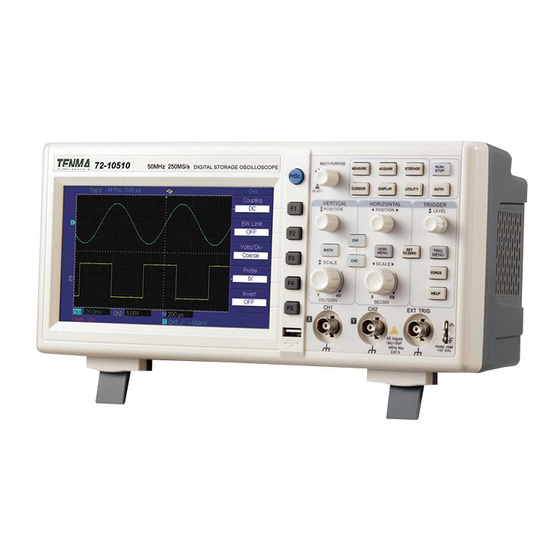
Model 72‐7610/72‐10510 User Manual Figure 1‐2: 72‐10510 Panel Diagram ‐7‐inch TFT color LCD display Figure 1‐3: User Interface Menu Display (taking 72‐10510 as an example) 2. General Inspections It is recommended to inspect the oscilloscope according to the following steps. 1. Inspect whether there are damages caused by transportation In case of badly damages to packing box or foamed plastic mat, you should replace immediately. 2. Accessories inspection 5 ... -
Page 8: Function Inspections
Model 72‐7610/72‐10510 User Manual For provided accessories details, description has been made in “Accessories” section of this user manual. If you find any accessory is missing or damaged, please contact Tenma distributors or the local offices. 3. Check the main instrument In case of damages to the appearance of instrument, abnormal operation or failure to pass the performance tests, please contact Tenma distributors or the local offices. If the instrument is damaged due to transportation, please pay attention to keeping the package, notify the transportation department and Tenma. They will make arrangement for repair or replacement. 3. Function Inspections Conduct a fast functional inspection to verify whether the oscilloscope runs normally. Please take the following steps: Power on the oscilloscope Users can power on the oscilloscope with voltage supply of AC 100V – AC 240V and ... - Page 9 Model 72‐7610/72‐10510 User Manual Figure 1‐5 Setting of Probe Attenuation Rate Switch It is required to set probe attenuation coefficient on the oscilloscope. Attenuation coefficient changes the vertical range rate of instrument, thus making the measurement result correctly reflect the amplitude of measured signals. Probe attenuation coefficients are set in the following ways: press F4 to make the menu display 10× . Figure 1‐6 Setting of Attenuation Coefficient on the oscilloscope ...
-
Page 10: Probe Compensation
Model 72‐7610/72‐10510 User Manual Figure 1‐7 Probe Compensation Signal 4. Probe Compensation When connecting the probe with any input channel for the first time, it is required to make the adjustment, matching the probe with the input channel. Probe without being compensated and calibrated will cause measurement error or mistake. To adjust probe compensation, follow the steps below: 1. -
Page 11: Automatic Setting Of Waveform Display
Model 72‐7610/72‐10510 User Manual Figure 1‐8b: Correct compensation Warning: To avoid electrical shock when measuring high voltage with probe, please ensure that the insulation lead of the probe is in good condition and do not contact the metal part of the probe when connecting to power supply. 5. Automatic Setting of Waveform Display The oscilloscope has automatic setting function. According to input signals, automatically adjust the vertical deflection factor, scanning time base and trigger mode ... -
Page 12: Introduction To The Horizontal System
Model 72‐7610/72‐10510 User Manual Figure 1‐9 Vertical Control Area on the Panel Model 72‐7610 (Left) Model 72‐10510 (Right) 1. Use the vertical position knob to move the vertical position of the waveform display on the LCD screen. By default, waveforms should be displayed at the center of the screen. 2. Users should see the waveform will move vertically upward and downward when the knob is rotated. 3. Users can also change the waveform scale by rotating the scale knob on the vertical system. Please notice that the “V/div” will be changed to indicate the corresponding vertical scale level. 4. -
Page 13: Introduction To The Trigger System
Model 72‐7610/72‐10510 User Manual Figure 1‐10 Horizontal Control Area on the Panel 72‐7610 (Left) 72‐10510 (Right) 1. Use horizontal SCALE knob to change horizontal time base scale settings and observe the state information changes. Turn horizontal SCALE knob to change “s/div” time base scale, and you can find corresponding changes in the time base scale display of corresponding channel in the status bar. Horizontal scanning rate steps up in the multiples of 1, 2 and 5 e.g. 1 ms /div‐>2 ms/div‐>5 ms/div‐>10ms /div…. etc. Note: the horizontal time base range of 72‐7610/72‐10510 varies between 2ns/div and 50s/div. Details are listed in technical specifications. 2. Use horizontal POSITION knob to adjust the signal horizontal position in the waveform window. Horizontal POSITION knob controls the signal trigger shift. When applied to trigger shift, the waveform horizontal movement can be observed along with POSITION ... -
Page 14: Ⅴ. Specifications
Model 72‐7610/72‐10510 User Manual Figure 1‐11 Trigger Menu on the Panel 72‐7610 (Left) 72‐10510 (Middle) Trigger Menu Display (Right) More trigger system settings will be explained in “Operations” section of this user manual. Ⅴ. Specifications Unless otherwise specified, all technical specifications are applicable to the probes with attenuation switch set as 10× and to the oscilloscope. The oscilloscope must first meet the following two conditions to satisfy those specification standards: The oscilloscope must continuously run for over half an hour in the operating temperature environment. ... - Page 15 Model 72‐7610/72‐10510 User Manual Maximum input 400V (DC+AC peak value, 1MΩ input impedance) voltage Time delay between 150ps Channels (Typical) Horizontal System Specifications Waveform Sin (x) /x interpolation 25pixels/div Horizontal resolution Record length 2×512k sampling point Storage depth 25k 72‐7610 2ns/div‐50s/div Scanning scope 72‐10510 2ns/div‐50s/div Sampling rate and ±50ppm (any interval≥1m) delay time accuracy Measurement Single time: ± (1 sampling ...
- Page 16 Model 72‐7610/72‐10510 User Manual 72‐10510: ±5% (When vertical sensitivity is 1mV/div or 2mV/div) ±4% (When vertical sensitivity is 5mV/div) ±3% (When vertical sensitivity is 10mV/div ‐20mV/div) 72‐7610: When vertical position is 0 and N≥16: ± (4%×reading + 0.1div + 1mV) at 2mV/div and 5mV/div; ± (3%×reading + 0.1div + 1mV) from 10mV/div to 5V/div; When vertical position is not at 0 and N≥16: ±[3%×(reading + vertical position reading) + (1%×vertical position reading)]+0.2div) from 2mV/div to 200mV/div + 2mV DC measurement The setting value from 200mV/div to 5V/div plus 50mV accuracy (average sampling 72‐10510: mode) When vertical position is 0 and N≥16: ± (5%×reading+0.1div+1mV) and selects 1mV/div or 2mV/div; ± (4%×reading+0.1div+1mV) and selects 5mV/div; ± (3%×reading+0.1div+1mV) and selects 10mV/div or 20mV/div; When vertical position is 0 and N≥16: ...
- Page 17 Model 72‐7610/72‐10510 User Manual Bandwidth for Each Model Analog Real‐Time Model Rise Time Bandwidth Bandwidth 72‐7610 150MHz 100MHz 2.3ns 72‐10510 25MHz 25MHz 14ns Trigger System Specifications Trigger sensitivity ≤1div Range of trigger level Interior From the screen center ±5div EXT ±3V EXT/5* ±15V Trigger level accuracy ...
-
Page 18: General Technical Specifications
Model 72‐7610/72‐10510 User Manual Alternating Trigger CH1 trigger Edge, pulse width, and video CH2 trigger Edge, pulse width, and video Note: No EXT/5 function for 72‐10510. Measurements Voltage difference between cursors (△V), Cursor Parameters Time difference between cursors (△T), Cursor Reciprocal of △T (Hz) (1/△T) Voltage value and time value of Track point of waveform Vpp, Vamp, Vmax, Vmin, Vtop, Vbase, Vmid, Average, Vrms, Automatic Overshoot, Preshoot, Frequency, Period, Rise Time, Fall measurement Time, +Width, ‐Width, +Duty, ‐Duty, Delay ... - Page 19 Model 72‐7610/72‐10510 User Manual Probe Compensator Output Output voltage (Typical) About 3Vpp, when the load≥1MΩ Frequency (Typical) 1kHz Interface Function 72‐7610 1 USB device; 1 USB Host Standard configuration 72‐10510 1 USB OTG Optional component LAN communication port for 72‐7610 Power Source Power voltage 100‐240VAC RMS, 45‐440Hz CAT II Power consumption Less than 30 VA F1.6AL 250V (Fuse is inside the instrument Fuse ...
-
Page 20: Ⅵ. Operations
Model 72‐7610/72‐10510 User Manual Ⅵ. Operations Until now, you have had basic understanding about the vertical, horizontal, and trigger system controls of the oscilloscope. We recommend you to re‐read the “Functions” section if you are still not familiar with the basic operation controls. In this section, you will learn different settings related to the oscilloscope: 1. Set the Vertical System (CH1, CH2, MATH, REF, OFF) 2. Set the Horizontal System (MENU or HORI MENU) 3. Set the Trigger System (MENU, TRIG MENU, 50% and FORCE) ... - Page 21 Model 72‐7610/72‐10510 User Manual Description Function Setting Menu Block the DC component of input AC signal. Coupling Pass through DC and AC components DC of input signal Grounding Disconnect input signal. Limit bandwidth to 20MHz to reduce Bandwidth On display noise. Limit Off Full bandwidth Rough Set vertical deflection factor by coarse adjustment adjustment based on 1‐2‐5 scale. Rough adjustment setting range is V/div Fine further subdivided for fine adjustment adjustments to improve vertical resolution. 1× ...
- Page 22 Model 72‐7610/72‐10510 User Manual Figure 2‐1 Blocked Signal DC Component If you press F1 to select DC coupling, both the DC and AC components of the signal being measured in CH1 can pass. The waveform display is shown in the figure below. Figure 2‐2 Simultaneous Display of Signal DC and AC Components ...
- Page 23 Model 72‐7610/72‐10510 User Manual to set bandwidth limit as OFF, CH1 is with full bandwidth. All AC and DC high‐frequency components in the measured signal can pass through. The waveform is displayed as below. Figure 2‐4 Waveform Display When Bandwidth Limit is OFF If you press F2 again to set the bandwidth limit as ON, the noises or high‐frequency component over 20MHz in measured signal shall be attenuated. The waveform is displayed ...
- Page 24 Model 72‐7610/72‐10510 User Manual You can press F4 function key to select different probe coefficients for the input channel as showed in the figure below. Figure 2‐6 Probe Attenuation Coefficient Setting in Channel Menu Vertical V/div adjustment setting Vertical deflection factor V/div scale adjustments consist of coarse adjustment and fine adjustment by pressing F3 function key. Coarse adjustment, V/div can be adjusted by multiplying 1, 2 and 5, e. g. 10mV/div‐>20mV/div ‐>50mV/div…. etc. Fine adjustments refer to changing deflection factor with smaller stepping within the current vertical scale. ...
- Page 25 Model 72‐7610/72‐10510 User Manual Figure 2‐8 Vertical Channel Inverted Setting (Invert: OFF) Figure 2‐9 Vertical Channel Inverted Setting (Invert: ON) Mathematical operation function The oscilloscope supports mathematical operation function for the input signals. The figure below shows the match result for CH1 + CH2 as an example. ...
- Page 26 Model 72‐7610/72‐10510 User Manual By pressing F1 at math menu, you can select mathematic operations or FFT operations. Table 2‐2: Math Menu Function Menu Settings Description Type Math Mathematic operations Signal source CH 1 You can select signal source 1 as CH 1 1(F2) CH 2 or CH2 + Signal source 1 + signal source 2 – Signal source 1 ‐ signal source 2 Operator (F3) × Signal source 1 × signal source 2 ÷ Signal source 1 ÷ signal source 2 You can select signal source 2 as CH1 Signal source 2 CH1 or CH2 (F4) ...
- Page 27 Model 72‐7610/72‐10510 User Manual Select FFT window Assuming that YT waveform is continuously repeated, the oscilloscope shall conduct FFT conversion for time record with finite length. In this case, when the cycle is an integer, YT waveforms are of the same amplitude at starting and ending positions, without interrupting. ...
- Page 28 Model 72‐7610/72‐10510 User Manual The best amplitude Mainly used for single resolution and the Blackman frequency signal seeking for worst frequency higher sub harmonic. resolution. Load a reference waveform Any of the pre‐saved waveform can be loaded Explanation of nouns by pressing the REF FFT resolution: defined as the quotient of sampling and operation point. button on 72‐7610. For When the number of operation point is fixed, the lower the sampling rate is, 72‐10510, pressing the the better the FFT resolution will be. STORAGE button starting load the pre‐saved Nyquist ...
-
Page 29: Set The Horizontal System
Model 72‐7610/72‐10510 User Manual Assuming that users have already stored a waveform into the internal memory location 3. To load this waveform back to Ref A, users should do the following on the Load function menu. Select the memory location 3 by using multi‐purpose knob Select DSO on the Disk selection Press F4, a loading progress bar will be shown on the screen. If loading is done, a white waveform should be displayed on the screen labelled Ref A. If no waveform is stored at the selected memory location, you will see a system message show “no data in the position” Users can turn off the Ref A reference waveform by pressing OFF F3 button on the load function menu. Attention: Loading the pre‐saved waveform into Ref B follows the same procedure as above. If waveform is stored to the USB device, 200 available memory locations can be selected. Please see “Set the Storage and Load System” for how to save a waveform to USB device. ... - Page 30 Model 72‐7610/72‐10510 User Manual The horizontal position control knob is used to adjust the horizontal position of channel waveform (including mathematical operations). The resolution of the horizontal position control knob varies at different time bases. The horizontal scale control knob is used to change the time base shown as s/div of channel waveform. If the extension time base is turned on, the window width will be changed ...
- Page 31 Model 72‐7610/72‐10510 User Manual Under window extension time base, there are two display areas, as shown in the figure above. The original waveform is displayed in the upper part; this area can be moved left and right by turning the POSITION knob or can be zoomed and shrunk by turning the SCALE knob. The waveform generated through horizontal extension time base of the selected original waveform area shall be displayed in the lower part. As the waveform displayed in the whole lower part corresponds to the selected area in the upper part, the extension time ...
-
Page 32: Set The Trigger System
Model 72‐7610/72‐10510 User Manual Trigger control area of the operation panel includes: trigger level adjustment knob; trigger menu key: TRIG MENU for 72‐10510 and [MENU] for 72‐7610. For 72‐7610, the trigger level can be set as 50% of signal vertical midpoint by the 50% button. For 72‐10510, it is achieved by pressing SET TO ZERO key. Forcing trigger shall be achieved by pressing FORCE button. FORCE trigger is: a trigger signal generated by force is mainly applied in trigger mode and “normal” and “single” mode. 3. Set the Trigger System Trigger level knob: trigger knob is used to adjust the trigger level (To set the voltage level corresponding to trigger point). Trigger level knob: trigger knob is used to adjust the trigger level (To set the voltage level corresponding to trigger point). Trigger Type The oscilloscope supports: edge, pulse width, video trigger and alternating trigger; Edge Trigger: Edge trigger mode refers to triggering of trigger threshold on the input signal edge. ... - Page 33 Model 72‐7610/72‐10510 User Manual Function Description Settings Menu Type Edge CH1 Set CH1 as the triggering signal source CH2 Set CH2 as the triggering signal source Set external trigger input channel as the EXT triggering signal source Set external trigger source (divided by 5) Source (F2) EXT/5 ...
- Page 34 Model 72‐7610/72‐10510 User Manual Reject low‐frequency component Low‐frequency of the triggering signal (below rejection 80kHz signals) Pulse Width Trigger For pulse width trigger, the trigger time shall be subject to pulse width of the triggering signal. You can capture abnormal pulse by setting pulse width conditions. Table 2‐8 (Page 1) Function Menu Settings Description Pulse Type width Set CH1 as triggering signal source CH1 CH2 Set CH2 as triggering signal source Set external trigger input channel as EXT triggering signal source Set external trigger source (divided Source (F2) ...
- Page 35 Model 72‐7610/72‐10510 User Manual trigger signal. Set the positive pulse width as Trigger Positive trigger signal polarity Set the negative pulse width as (F2) Negative trigger signal Set to automatic trigger. The oscilloscope will continuously Automation perform data acquisition without triggering signal. Set to normal trigger. The oscilloscope will only perform data Mode (F3) Normal acquisition when there is triggering signal. Set to single trigger. The oscilloscope will only perform a Single cycle of data acquisition when there is triggering signal. Block the DC component of AC triggering signal Pass through DC and AC DC ...
- Page 36 Model 72‐7610/72‐10510 User Manual CH2 Set CH2 as triggering signal source Set external trigger input channel EXT as triggering signal source Set external trigger source (divided by 5) as trigger level EXT/5 range (Only for 72‐7610) Set AC power line as trigger source AC Line PAL Select to PAL video standard Standards (F3) NTSC Select to NTSC video standard Set trigger synchronization to All lines video line Set trigger to synchronize in Synchronization designated video line number. (F4) Designated Adjust video line number by using line the multipurpose knob in the upper part of front panel. ...
- Page 37 Model 72‐7610/72‐10510 User Manual Figure 2‐15 Video Trigger: Field Synchronization Alternating Trigger During alternating trigger, the trigger signal comes from two input channels, CH1 and CH2 alternately. Alternating trigger is useful for observing two signals with different frequencies. See the figure below for the display of triggered alternating waveform and Table 2‐11 for triggered alternating menu setting: ...
- Page 38 Model 72‐7610/72‐10510 User Manual Trigger mode Automation Auto trigger mode is set. Trigger coupling AC AC trigger coupling mode is set. Force Trigger Force trigger can be understood as forcing the oscilloscope to refresh the data acquisition process, so users can observe waveform capturing. To enable force trigger, please press FORCE button. ...
-
Page 39: Set The Acquire System
Model 72‐7610/72‐10510 User Manual acquisition only when trigger conditions are satisfied. 4. Set the Acquire System Users can change the data acquisition mode by pressing ACQUIRE button as shown in the figure below. Figure 2‐17 Function Key of Sampling System While ACQUIRE button is pressed, the data acquisition setting menu for the oscilloscope will display. Table 2‐11 Acquire Menu Function Settings Description Menu Sampling Set to sampling acquisition mode ... - Page 40 Model 72‐7610/72‐10510 User Manual By changing the acquisition setting, users can observe the input signal in different ways. The example below is a noise waveform acquired by different acquisition settings of the oscilloscope. Figure 2‐18 shows the original signal in sampling mode , users can see that the waveform displayed includes relative large noise. Figure 2‐19 shows the same signal with in average mode with 64 averages , please observe that the waveform display is becoming much smoother. Figure 2‐18 Waveform display in sampling mode ...
-
Page 41: Set The Display System
Model 72‐7610/72‐10510 User Manual modulation signal. 4. Please select average sampling mode when hoping to reduce the random noise in displayed signals. Explanation of nouns Real‐time sampling mode: Data sampling with the system real‐time rate is used to observe the waveform within the rate. Equivalent sampling mode: Data sampling with the rate higher than the maximum. This is used to ... -
Page 42: Set The Storage And Load System
Model 72‐7610/72‐10510 User Manual Vector Display as vector of sampling points Types (F1) Dots Display any of the sampling points Display Y‐axis as voltage level of input YT signal and X‐axis as time Format Display Y‐axis as CH2 voltage level of (F2) X Y input signal and X‐axis as CH1 voltage level of input signal Real‐time updating (Display) of the Off acquired signal. 1s Display the acquired signal every 1s Persist (F3) 2s Display the acquired signal every 2s 5s Display the acquired signal every 5s Accumulate to display all the Infinite acquired Waveform ... - Page 43 Model 72‐7610/72‐10510 User Manual Users can enter the storage and load menu by pressing the STORAGE button. Function Key of Sampling System (STORAGE) Below steps will guide you to store a waveform into the internal memory of the oscilloscope: ...
- Page 44 Model 72‐7610/72‐10510 User Manual 1/2 Press F2 to select the waveform source to be saved. Use the multi‐purpose knob to select the storage memory destination. Press F4 to store the waveform Attention: Any waveform storage will overwrite previous memory space at the same memory location. To load a waveform from the internal memory, please refer to the item, “Load a Reference Waveform” in this section. ...
- Page 45 Model 72‐7610/72‐10510 User Manual Menu Select to store an acquired waveform into DSO the internal memory of the oscilloscope Disk (F1) Select to store an acquired waveform into USB the USB device Select normal data length (Same data Normal number as displayed) Length (F2) Select long data length (Same as data Long number as data buffered in the DSO FIFO) —— —— —— —— —— —— Previous —— Go to the previous page 2/2 [F5] Press F1 to select USB as storage destination. Press F2 to select Normal storage. Press F5 to go to the first page of the function menu. Use the multi‐purpose knob to select the storage memory destination (please notice that there will be 200). ...
- Page 46 Model 72‐7610/72‐10510 User Manual Select waveforms from CH2 channel to be CH2 saved Destination (Position of the internal memory) where the waveform will be Dest (@) saved. There are 20 sets of internal 1~20 memory available to storage waveform navigated by the multipurpose knob. Save [F4] —— Store waveform Next page —— Get to the next page 1/2 Press F1 to select Setup. Use the multi‐purpose knob to select the storage memory location. Press F4 to store the setting Attention: Any storage of the setting will over‐write previous memory space in the same memory location. Table 2‐15 Setting Storage Menu (Page 2) Function Settings Description ...
- Page 47 Model 72‐7610/72‐10510 User Manual If no pre‐stored setting is in the memory location, a warning, “no data in the position” will appear. Below steps will guide you to store a bitmap to USB device: Insert a USB disk into the “USB Host” interface. If the USB is connected successfully, you should see the “USB device install successfully” notification on the screen. Press Storage button and you will see the following menu. Table 2‐16 Bit Map File Storage Menu (Page 1) Function Settings Description Menu Wave Select to store an acquired waveform Setup Select to store a setting Type (F1) Select to store a bitmap file into the USB disk Bit Map only Select waveforms from CH1 channel to be CH1 saved Source (F2) Select waveforms from CH2 channel to be ...
-
Page 48: Set The Utility System
Model 72‐7610/72‐10510 User Manual memory available to store bitmap file navigated by the multipurpose knob. Save [F4] —— Press to store a bitmap file —— Use the multi‐purpose knob to select the storage memory destination (please notice that 200‐group data storage is available). Press F4 to store a bitmap file into a USB disk; Remove the USB disk. 7. Set the Utility System By pressing the ... - Page 49 Model 72‐7610/72‐10510 User Manual Recorder See Table Set waveform recording operation (F3) 2‐20 Language Press to change to different system Language (F4) language Next(1/3) Press to next Utility Function Menu (F5) page Table 2‐18 Utility Menu Page 2 Function Menu Settings Description Reset (F1) Reset to factory default settings To turn on the channel fast correction On function Quick Correction (F2) To turn off the channel fast OFF correction function ...
- Page 50 Model 72‐7610/72‐10510 User Manual Select CH1 as recording signal CH1 source Select CH2 as recording signal Source (F1) CH2 source Select CH1 and CH2 as recording CH1+ CH2 signal sources Operation See Table 2‐21 Sub‐menu for operations (F2) for detail Save waveform recording into USB memory; Save (@) Select from 1‐200 memory (F3) locations; Press F3 to save. Load the waveform recording into USB memory; Load (@) Select from 1‐200 memory (F4) ...
- Page 51 Model 72‐7610/72‐10510 User Manual select the output condition for the logical result between the templates of area and the input source. You can enable PASS/FAIL function by pressing F1 on PASS/FAIL function menu. After turning on this function, you can see the total number of waveform being processed, the number of waveform passed and the number of waveform failed on the LCD screen. Table 2‐22 Pass/Fail Function Menu Function Settings Description Menu ON Press to turn on PASS/FAIL function Status (F1) OFF Press to turn off PASS/FAIL function Select CH1 as the detection signal CH1 source Select CH2 as the detection signal ...
-
Page 52: Set The Measurement Parameters
Model 72‐7610/72‐10510 User Manual Create (F1) / According to adjustment, build horizontal and vertical Pass/Fail tolerance range Horizontal 1‐200 Press [F2] to select horizontal length and (F2 and @) Pixel use the multi‐purpose knob to set the pixel length for the horizontal length Vertical 1‐100 Press [F3] to select vertical length and (F3 and @) Pixel use the multi‐purpose knob to set the pixel length for the vertical length Return (F4) / Return to pass detection menu You will need to press F1 to confirm creating the pixel template after setting the horizontal and vertical length of the pixels. ... -
Page 53: Set The Cursor Measurement
Model 72‐7610/72‐10510 User Manual function menu Source (F2) CH1 Select CH1 as source CH2 Select CH2 as source Volt (F3) Select different voltage parameters Time (F4) Select different time parameters Parameters Press to display all the measurement (F5) parameters of the input source. Or, press to turn off parameter display. Voltage Parameters Below are the automatically measured voltage parameters for the oscilloscope and their definitions: Vpp: P eak‐to‐peak voltage. Vmax: Maximum voltage. Vmin: Minimum voltage. Vmid: Medium voltage. Vamp: The voltage amplitude from waveform top to bottom. Vtop: The voltage value from waveform top to GND (Ground). Vbase: The voltage value from waveform base to GND (Ground). Over‐shoot: The ratio of (Vmax – Vtop) to voltage amplitude (Vamp). ... -
Page 54: System Message Examples And Troubleshooting
Model 72‐7610/72‐10510 User Manual Figure 2‐25 Function Key of Sampling System (CURSOR) The oscilloscope supports 3 different types of cursor measurements. Volt: Voltage (Vertical System) Time: Time (Horizontal System) Track: Volt and Time working at the same time. At the Volt cursor measurement, users should be able to see ΔV, Va, and Vb parameters on the display screen, where ΔV is the difference between Va and Vb; Users can move Va courser by rotating the multi‐purpose knob. Once the location of Va courser is an ideal one, users can press the multi‐purpose knob (the SELECT button on 72‐7610) to switch to Vb; Users can move Vb cursor by rotating the multi‐purpose knob in the same way as moving the Va cursor. At the Time cursor measurement, users can perform referring to Volt cursor measurement by using the multi‐purpose knob and SELECT button on 72‐7610. ... - Page 55 “Loading” Progress Bar When users are loading waveform and setup files, system will show the “Load” progress bar. Please wait until the whole loading progress completes. Troubleshooting: After pressing the power button, the screen is dark and has no display: ① Check if the power connector is properly connected to the power socket ② Check if the power button is pressed to the ON position ③ Restart the instrument after completing the above checking ④ If the oscilloscope still does not work normally, please contact with Tenma Cannot acquire signal waveform ① Check if the probe BNC connector is properly connected to the oscilloscope ② Check if the probe is working properly by connecting the probe to “Probe compensation signal output” ③ Check if the probe is properly connected to the device under test ④ Try to acquire signal again ...
-
Page 56: Ⅶ. Maintenance & Cleaning
Model 72‐7610/72‐10510 User Manual The waveform refreshing is slow: ① Check if the Acquire mode is “Average” mode ② In “Average” mode, waveform refreshing is slow because it displays the average value of the waveform to reduce the random noise in displayed signal. ③ Change to “Sample” mode or “Peak” mode for the desired display. The waveform display do not smooth ① The horizontal time base division value may be too small, increase the horizontal time base division to improve the waveform smoothness; ... - Page 57 Model 72‐7610/72‐10510 User Manual Tenma Test Equipment 405 S. Pioneer Blvd. Springboro, Oh 55 ...
Need help?
Do you have a question about the 72-7910 and is the answer not in the manual?
Questions and answers