
Related Manuals for Tenma 72-2650


Summary of Contents for Tenma 72-2650
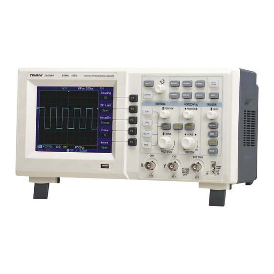
- Page 1 Digital Storage Oscilloscope Model No. 72-2650, 72-8705A, 72-8710A 72-8225A & 72-10510...
-
Page 2: Product Overview
When using electrical appliances, basic safety precautions should always be followed to reduce the risk of fire, electric shock and injury to persons or property. Read all instructions before using the appliance and retain for future reference. • This meter is designed to meet IEC61010-1, 61010-2-032, and 61010-2-033 in Pollution Degree 2, Measurement Category (CAT II 150V when switched to 1X and 300V CAT II when switched to 10X) and double Insulation. -
Page 3: Operating Parameters
OPERATING PARAMETERS • The oscilloscope also has high performance index and powerful functions required for faster measurements. Faster signals can be observed with the oscilloscope via 500MS/s (or 1GS/s) real‐time sampling and 25GS/s (or 50GS/s) equivalent sampling. • Powerful trigger and analysis ability make it easier to capture and analyse waveforms. -
Page 4: Operation
OPERATION Accessing signals • Power on the unit then allow the self test to complete. • Press UTILITY button then F1 and the screen will display DEFAULT SETUP. Note: The meter has dual input channels plus one external trigger input channel. •... - Page 5 Press CH1, CH2, MATH or REFERENCE and the screen shows the corresponding operation menu, sign, waveform and range status information. • Press OFF to disable the selected channel (72-2650). Horizontal control panel • Horizontal position control adjusts the position of the waveform window by adjusting the trigger shift of the signal.
-
Page 6: Instrument Setup
INSTRUMENT SETUP Vertical system setup • Each channel CH1 or CH2 has it’s own vertical menu. Each channel should be set up individually. • Press CH1 or CH2 and the system will display the operation menu for that channel. Functions Menu Setup Notes Intercepts the DC quantities of the input signal. - Page 7 Channel bandwidth setup • If for example a signal is applied to CH1 which is a pulse signal that contains high frequency oscillation. • Press CH1 to select Channel1. • Press F2 to set the BANDWIDTH LIMIT OFF so it is set up as full bandwidth. •...
- Page 8 Operating Math functions • Math functions are displays of +, -, ÷ FFT mathematical results of CH1 and CH2. The menu options are:- Functions Menu Setup Notes Type Math To carry out +, -, x, ÷ functions Signal source 1 Set signal source 1 as CH1 waveform Set signal source 1 as CH2 waveform Operator...
-
Page 9: Reference Waveform
Select the FFT window • Assuming the YT waveform is constantly repeating itself, the oscilloscope will carry out FFT conversion of time record of a limited length. When this cycle is a whole number, the YT waveform will have the same amplitude at the start and finish. There is no waveform interruption. -
Page 10: Horizontal Position
Press REF B and select the second signal source for the math function repeating step 3 Note: To measure and observe such waveforms you can compare the current waveform with the reference waveform for analysis. Press REF to display the reference waveform menu. See following table: Functions Menu Setup Notes... -
Page 11: Icon Definitions
Icon definitions Represents the memory position of the current waveform. Represents the memory position of the triggering point. Represents the position of the triggering point in the current waveform window. Horizontal time base (main time base) ie: sec/div. Horizontal distance between the triggering position and the window centre point. Definitions •... - Page 12 • Generally adjusting the time base lower will result in appropriately Lissajous figures of better display quality. • The following functions have no effect in the X-Y display mode:- Auto measurement mode Cursor measurement mode Reference or math waveform Vector display type Horizontal position control Trigger control Setting up the Trigger system...
- Page 13 Functions Menu Setup Notes Type Edge Intercept DC quantities of the input signal Allow AC and DC quantities of the input signal to pass Trigger coupling H/F reject Reject high frequency quantities above 80kHz of the signal L/F reject Reject low frequency quantities below 80kHz of the signal Pulse Trigger •...
-
Page 14: Video Trigger
Video Trigger • By selecting video trigger you can carry out field or line trigger with NTSC or PAL standard video signals. Default trigger coupling is DC. Functions Menu Setup Notes Type Video Set Ch1 as the trigger signal Set CH2 as the trigger signal Set the external trigger input channel as the trigger signal Trigger source EXT/5... - Page 15 Functions Menu Setup Notes Type Edge Set trigger mode to EDGE Trigger source Alternate Set CH1 and Ch2 to alternate trigger Inclination Rising Set trigger inclination as rising edge Trigger mode Auto Set trigger mode to automatic Trigger coupling Set trigger coupling mode to AC Set up for Trigger Coupling mode •...
- Page 16 OPERATION Trigger Source - Trigger can be obtained from various sources: Input channel (CH1 or CH2), external trigger (EXT, EXT/5) or grid. Input channel - the most common trigger source is input channel. The selected trigger source can operate normally whether the input is displayed or not. External trigger - this type of trigger source can trigger in a third channel while acquiring data in two other channels.
- Page 17 Functions Menu Setup Notes Sample Turn on the ordinary sampling mode Peak detect Turn on the peak detect mode Acquisition Mode Average Set the average sampling and display the average number of times Set the average number of times in multiples of 2 ie: 2, 4, Average number of 2-256 8, 16, 32, 64, 128, 256 To change the average number of...
-
Page 18: Operating Procedure
Setting up the Display System • The DISPLAY button on the control panel is the function key for the display system. Functions Menu Setup Notes Vector Sampling points are linked for display Display type Dots Sampling points are directly displayed Operating mode of the oscilloscope X-Y is the display mode Format CH1 is X input CH2 is Y input. - Page 19 Functions Menu Setup Notes Setup Select the front panel setup menu Setup (save Maximum 10 front panel setups can be saved. Select with 1~10 position) the multi-function control on front panel Save Save the setting Recall Recall the setting Functions Menu Setup Notes Bitmap...
- Page 20 Auto Calibration: you can correct measurement errors caused by environmental changes with the auto calibration function. This process can be run selectively when necessary. To make calibration more accurate, power on the oscilloscope and allow 20 minutes to warm up then press UTILITY button and follow the on screen instructions. Choose your language: The Oscilloscope can be operated in several languages, press UTILITY button and choose the desired language.
- Page 21 Automatic measurement of time parameters • The DSO series oscilloscope can automatically measure the following parameters. • Rise time - the time taken by the waveform to rise from10% to 90%. • Fall time - the time taken for the waveform to fall from 90% to 10%. •...
-
Page 22: Cursor Measurement
Cursor Measurement • The CURSOR button on the control panel is the function key for cursor measurement. • Adjust the cursor position by turning the multi-function control. Functions Menu Setup Notes CH1/CH2/ Select the measurement channel Channel MATH CH1/CH2/ Channel Select the reference channel MATH Select to return to the parameter measurement display... -
Page 23: Functions Menu
Functions Menu Setup Acquisition mode Adjust to ‘Sampling’ or ‘Peak Measurement’ Cursor Disabled Display format Set to YT Display type Vector Horizontal position Adjusted SEC/DIV Adjust according to signal frequency Trigger coupling Trigger Holdoff Minimum value Trigger level Set at 50% Trigger mode Auto Set to CH1 but if there is no signal in CH1 and CH2 applies a... -
Page 24: Specification
If the display type is vector, the connection between sampling dots may produce a ladder waveform. Set the display type to dot to solve this issue. SPECIFICATION Sampling Sampling modes Real time Real time Equivalent Sampling rates 72-2650 1GS/s 50GS/s 72-8710A 1GS/s 50GS/s 72-8705A 1GS/s 50GS/s 72-8225A... - Page 25 Vertical A/D converter 8-bit resolution, two channels sampled simultaneously 72-2650 2mV/div~5V/div Deflection factor VOLTS/DIV Range at input BNC 72-10510 72-8225A 1mV/div~20V/div 72-8705A 72-8710A Position range ±10div (72-10510) Selectable bandwidth limit 20MHz (Typical) Low frequency response ≤10Hz at BNC (AC coupling, -3dB) 72-2650 ±...
-
Page 26: Pulse Trigger
Line range: 1-525 (NTSC) and 1-625 (PAL) Alternate Trigger CH1 trigger Edge, pulse, video CH2 trigger Edge, pulse, video NOTE: EXT/5 function is only for 72-2650 and video trigger function for 72-2650 and 72-10510 Measurement Voltage difference (rV) between cursors, time Manual Mode difference (rT) between... -
Page 27: Interface Function
1 x USB device, 1 USB host 71-10510 72-8225A Standard Configuration 1 USB OTG 72-8705A 72 8710A Optional component LAN communication port for 72-2650 Power Source Mains voltage 100-240V AC rms 45-440Hz, CAT II Power consumption Less than 30VA Fuse F1.6AL 250V... -
Page 28: Maintenance
Dimensions 72-10510 72-8225A 72-2650 72-8705A 72-8710A WIDTH 320mm 306mm Size HEIGHT 150mm 147mm DEPTH 130mm 122mm Weight Exc Packaging 2.5kg 2.2kg Inc Packaging 4.0kg 3.3kg IP rating IP20 Adjustment interval Recommended calibration interval is one year MAINTENANCE Cleaning • Periodically wipe the case with damp cloth and mild detergent. Do not use abrasives or solvents for cleaning.
Need help?
Do you have a question about the 72-2650 and is the answer not in the manual?
Questions and answers