Advertisement
Quick Links
Advertisement

Subscribe to Our Youtube Channel
Related Manuals for Tenma 72-7630


Summary of Contents for Tenma 72-7630
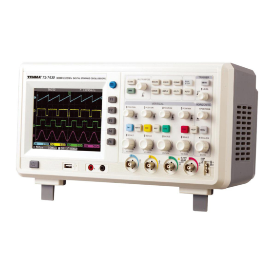
- Page 1 4 Channel Digital Storage Oscilloscope Model No. 72-7630...
- Page 2 When using electrical appliances, basic safety precautions should always be followed to reduce the risk of fire, electric shock and injury to persons or property. Read all instructions before using the appliance and retain for future reference. • This meter is designed to meet IEC61010-1, 61010-2-032, and 61010-2-033 in Pollution Degree 2, Measurement Category CAT II 600V and double Insulation.
- Page 3 OPERATING PARAMETERS • The oscilloscope also has high performance index and powerful functions required for faster measurements. Faster signals can be observed with the oscilloscope via 2GS/s (or 50GS/s) equivalent sampling. • Powerful trigger and analysis ability make it easier to capture and analyse waveforms.
- Page 4 OPERATION Probe compensation Accessing signals • Power on the unit then allow the self test to complete. • Press UTILITY button then F1 and the screen will display DEFAULT SETUP. Note: The meter has quad input channels plus one external trigger input channel. •...
- Page 5 Using the Autoset function • Connect the signal to be measured to the signal input channel. • Press AUTO and the oscilloscope will scan the time base and trigger mode and set the vertical deflection factor. You can manually adjust further after this process to get the optimum display.
- Page 6 INSTRUMENT SETUP Vertical system setup • Each channel CH1, CH2, CH3 or CH4 has it’s own vertical menu. Each channel should be set up individually. • Press CH1 to CH4 and the system will display the operation menu for that channel. Functions Menu Setup Notes...
- Page 7 Channel bandwidth setup • If for example a signal is applied to CH1 which is a pulse signal that contains high frequency oscillation. • Press CH1 to select Channel1. • Press F2 to set the BANDWIDTH LIMIT OFF so it is set up as full bandwidth. •...
- Page 8 Operating Math functions • Math functions are displays of +, -, ÷ FFT mathematical results of CH1 and CH2. The menu options are:- Functions Menu Setup Notes Type Math To carry out +, -, x, ÷ functions Signal source 1 Set signal source 1 as CH1 waveform Set signal source 1 as CH2 waveform Set signal source 1 as CH3 waveform...
- Page 9 Select the FFT window • Assuming the YT waveform is constantly repeating itself, the oscilloscope will carry out FFT conversion of time record of a limited length. When this cycle is a whole number, the YT waveform will have the same amplitude at the start and finish. There is no waveform interruption.
- Page 10 Reference waveform • Displays of the saved reference waveforms can be set on or off in the REF menu. • The waveforms are saved in non-volatile memory and identified with the following names: Ref A, Ref B. • To display (recall) or hide the reference waveforms use the following method: Press REF menu button on the front panel Press F2 to load and select the signal source using the MULTIPURPOSE control from 1 to 10 then press the control to confirm the selection.
- Page 11 Functions Menu Setup Notes Press F1 to switch between the main screen and Window expanded window Dual Xbase Enable the dual time base menu Holdoff 96.0000ns~1.5000s Adjust holdoff time using MULTIPURPOSE control Icon definitions Represents the signal frequency currently selected as trigger source.
- Page 12 Dual Time Base Function • The dual time base function is similar to window extension but there is a fundamental difference In the window extension mode you can magnify the waveform times whereas in the dual time base mode you can magnify details of the waveform being observed by thousands of times •...
- Page 13 Functions Menu Setup Notes Type Edge CH1, CH2 Set CH1, 2, 3 or CH4 as the signal source trigger signal CH3, CH4 Signal source EXT, EXT/5 Set the external trigger input channel as the signal source selection LINE Set to AC power trigger CH1 &...
-
Page 14: Table Of Contents
Video Trigger • By selecting video trigger you can carry out field or line trigger with NTSC or PAL standard video signals. Default trigger coupling is DC. Functions Menu Setup Notes Type Video CH1, CH2 Set CH1, 2, 3 or CH4 as the signal source trigger signal CH3, CH4 EXT, EXT/5 Set to external trigger or divide the external trigger by 5... - Page 15 Functions Menu Setup Notes Type Video Auto The system automatically samples waveform data when there is no trigger signal input. The scan baseline is shown on the display. When the trigger signal is generates it automatically turns to trigger scan. Mode Normal The system stops acquiring data when there is no trigger...
- Page 16 OPERATION Trigger Source - Trigger can be obtained from various sources: Input channel (CH1, CH2, CH3 or CH4), external trigger (EXT, EXT/5) or line. Input channel - the most common trigger source is one of the four input channels. The selected trigger source can operate normally whether the input waveform is displayed or not.
- Page 17 Functions Menu Setup Notes Sample Turn on the ordinary sampling mode Peak detect Turn on the peak detect mode Acquisition Mode Average Set the average sampling and display the average number of times Envelop Envelop sampling Set the average number of times in multiples of 2 ie: 2, 4, Average number 2-256 8, 16, 32, 64, 128, 256 To change the average number of...
- Page 18 Setting up the Display System • The DISPLAY button on the control panel is the function key for the display system. Functions Menu Setup Notes Vector Sampling points are linked for display Display type Dots Sampling points are directly displayed Operating mode of the oscilloscope X-Y is the display mode Format CH1 is X input CH2 is Y input...
- Page 19 Key Points Display Type: Vector display fills the spaces between adjacent sample points. Dots display only the sample points. Refresh Rate: is the number of times the digital storage oscilloscope refreshes the waveform display per second. The refreshing speed affects the capability to observe signal movements.
- Page 20 Setting up Alternative Functions • The UTILITY button on the control panel is the function key for alternative functions. • Use the multipurpose control to choose and select settings. Functions Menu Setup Notes Self Cal Run auto calibration Version Display model information and serial number Configuration Erase Clear all saved waveforms and setups...
- Page 21 Functions Menu Setup Notes In the unlock mode, default status is restored. The default LOCKED / Channel status is as follows: Bandwidth limit : full bandwidth, VOLTS/ UNLOCK DIV, coarse tune, Inversion: Off In the unlock mode, default status is restored. The default LOCKED / Acq set status is as follows: Sampling mode : normal sampling...
-
Page 22: Functions Menu Setup
Functions Menu Setup Notes CH1, CH2 Select one channel waveform as the delayed reference From CH3, CH4 waveform Take the centre point of 10%-90% of the waveform rising or From Edge Rise, Fall falling edge CH1, CH2 Select one channel waveform as the delayed measurement CH3, CH4 waveform Take the centre point of 10%-90% of the waveform rising or... -
Page 23: Functions Menu Setup
• Rise time - the time taken by the waveform to rise from10% to 90%. • Fall time - the time taken for the waveform to fall from 90% to 10%. • Positive pulse (+width) - pulse width of positive pulse at 50% amplitude. •... - Page 24 Cursor Measurement • The CURSOR button on the control panel is the function key for cursor measurement. • Adjust the cursor position by turning the multipurpose control. • You can move the cursor to carry out measurement in CURSOR mode. •...
-
Page 25: Trigger Source
Auto Setup • Auto setup simplifies the operation. Press AUTO and the oscilloscope can automatically adjust the vertical deflection factor and horizontal time base range according to the amplitude and frequency of the waveform, and also ensure a stable display of the waveform. •... - Page 26 Caution: Please select a suitable current/voltage converter module that fits the measurement range, and select an appropriate range. If you are not certain about the current being tested, make an estimation, use the which has the largest range, then select a suitable module range to suit the data. •...
- Page 27 • Check the trigger type. Use edge trigger for ordinary signals. A stable waveform is achieved only when the correct trigger mode is selected. • Try changing the coupling display to HF suppression or LF suppression to filter any noise interfering with the signal. •...
- Page 28 SPECIFICATION • Unless otherwise specified, all technical specifications apply to probes with 10X attenuation setting, and the oscilloscope has been powered on for 30 minutes at the specified ambient temperatures. Sampling Sampling modes Real time Equivalent CH1, CH2, single channel 2GS/s, Sampling rates 50GS/S CH3 CH4 two channels 1GS/s...
-
Page 29: Ext Ext/5
Low frequency response ≤10Hz at BNC (AC coupling, -3dB) When vertical sensitivity is 2mV/div ±4% (sample or average sampling mode) DC gain accuracy When vertical sensitivity is 5mV/div~5V/div ± 3% (sample or average sampling mode) When vertical position is zero and N≥16: ±(5%x reading+0.1div+1mV) and 2mV/div is selected;... - Page 30 Slew Rate Trigger Slew rate condition < Smaller than, > greater than, = equal to Slew rate range 40pV/s~1.6kV/s Video Trigger Internal 2 div Trigger sensitivity 400mV (video trigger, Typical) EXT/5 Signal format and line/field Supports standard NTSC and PAL frequency (video trigger type) Line range: 1-525 (NTSC) and 1-625 (PAL) Trigger Frequency Counter...
- Page 31 Digital Multimeter Range : 400mV, 4V, 40V, 400V DC voltage Precision : ± (1% + 5 quantization words) Range : 400mV, 4V, 40V, 400V AC voltage (40Hz~400Hz) Precision : ± (1.2% + 5 quantization words) Range : 400Ω, 4Ω, 40Ω, 400Ω, 4mΩ, 40MΩ Resistance Precision : ±...
- Page 32 MAINTENANCE Cleaning • Periodically wipe the case with damp cloth and mild detergent. Do not use abrasives or solvents for cleaning. Disconnect from the mains first. • Clean the measurement probe tips occasionally, as dirt on the probes can affect reading accuracy.
Need help?
Do you have a question about the 72-7630 and is the answer not in the manual?
Questions and answers