
Subscribe to Our Youtube Channel
Related Manuals for N&W Global Vending Krea


Summary of Contents for N&W Global Vending Krea
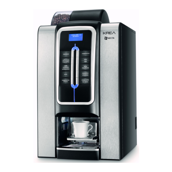
- Page 1 INSTALLATION, USE, MAINTENANCE Original instructions translation Krea Espresso Fresh brew 120V 60Hz UL NSF English H 4485EN00 09 - 2013 dition...
- Page 3 Targhetta di identificazione Identification label Valbrembo, 01/01/2012 DICHIARAZIONE DI CONFORMITA’ DECLARATION OF CONFORMITY DÉCLARATION DE CONFORMITÉ KONFORMITÄTSERKLÄRUNG DECLARACIÓN DE CONFORMIDAD DECLARAÇÃO DE CONFORMIDADE VERKLARING VAN OVEREENSTEMMING Italiano Si dichiara che la macchina, descritta nella targhetta di identificazione, è Direttive europee Sostituita da conforme alle disposizioni legislative delle Direttive Europee elencate a lato e suc- European directives...
-
Page 4: Declaration Of Conformity
Declaration of conformity for use The machine can be used by children and by people having reduced physical, sensorial or mental skills under the supervision of people responsible for their safety or The declaration of conformity with the European Direc- specifically trained on the use of the machine. -
Page 7: Table Of Contents
English TABLE OF CONTENTS PAGE PAGE dEclaration of conformity warning loaDEr mENu FOREWORD statistics idEntification of thE machinE and fEaturEs individual pricE in casE of failurE managEmEnt of thE coin box tubEs transport and storagE boilEr tEmpEraturE positioning of thE vEnding machinE tEst Eva dts tEcHNical cHaractEristics... -
Page 8: Foreword
IN CASE OF FAILURE In most cases, technical problems can be solved by me- Foreword ans of small interventions; we therefore suggest to read this manual carefully before contacting the manufacturer. The technical documentation forms an integral part In case of anomalies or malfunctioning which cannot be of the equipment and must therefore accompany solved, please contact: any movement or transfer of ownership in order to... -
Page 9: Positioning Of The Vending Machine
TECHNICAL CHARACTERISTICS POSITIONING OF THE VENDING MACHINE The machine is not suitable for outside installations, it Height inches 25.59 needs to be installed inside dry premises, with tempe- rature between 35.6° F and 89.6° F and it cannot be Height with coffee container inches 33.46 installed in environments in which jets of water are used... - Page 10 aymENt systEm afEtiEs The machine is supplied with electrical arrangement - door switch for systems with protocol Executive, BDV, MDB and for - boiler safety thermostat with manual reset monitoring 24 Vdc validators. Apart from the coin box housing, there is space for - air-break float jamming the optional installation of the most common payment - shutoff solenoid...
-
Page 11: Accessories 6
ACCESSORIES oNtaiNErs capacity The machine can be fitted with different combinations The machine can be fitted with accessories in order to of containers of a different type for dispensing different vary its performances. types of products. The installation kits are supplied with installation and The container: test instructions, which shall be scrupulously followed in order to maintain the safety of the machine. -
Page 12: Variable Combination Locks
VARIABLE COMBINATION LOCKS To change the combination: - Open the door of the device to avoid forcing rotation; Some models are supplied with variable combination locks. - Lightly lubricate using a spray inside the lock; The lock has a silver-coloured key with the standard - Insert the current change key (black) and turn it to the combination to be used for normal opening and closing change position (reference notch at 120°);... -
Page 13: Cleaning And Loading
Chapter 1 Cleaning and loading The machine is not suitable for outside installations, it needs to be installed inside dry premises, with tempera- ture between 32 and 104° F and it cannot be installed in environments in which jets of water are used for cleaning (i.e.: large kitchens, etc.). -
Page 14: Controls And Information
CONTROLS AND INFORMATION PRODUCT LOADING Before loading the products, please verify they are The controls and the information to the user are on the in strict accordance with the manufacturer instruc- external side of the door. tions regarding storage, storage temperature and The plates with the menu and the instructions are expiry date. -
Page 15: Machine Sanitization
MACHINE SANITIZATION STERILISATION OF THE MIXERS AND OF THE FOOD PRODUCTS CIRCUITS This manual shows the potential weak points and When the machine is installed and at least on a weekly includes information about controlling the possible basis, or more frequently depending on the use of the growth of bacteria. - Page 16 - The fans can be removed by simply pulling gently to astE coNtaiNErs free them; The waste containers can be easily extracted so that they can be quickly emptied and cleaned. For safety reasons, the containers can be handled only when the door is open.
- Page 17 ispENsiNg uNit astE rEsEt passWorD In order to reset the selections counter, it is necessary to When cleaning the dispensing unit, it is recommended to press some buttons in sequence (enter a password); remove it from the machine. With the closed door, proceed as follows: - Remove the saw tooth screws and the fixing screws of - Press and hold button no.
- Page 18 It is possible to programme the machine for displaying, for a few seconds, the number of dispensed items (total number of strokes) Krea Rev. X.XX Machine Board Rev. X.XX Total number of strokes = XXXXXX After that, the boiler is checked and the heating cycle is...
-
Page 19: Service Suspension
SERVICE SUSPENSION assWorD iNput WitH closED Door In order to safely perform some of the cleaning ope- If, for any reason, the vending machine remains off for a rations which require the machine to be in operation, period longer than the expiry dates of the products, it is it is possible to use the selection buttons in sequence necessary to: (password). -
Page 20: Installation
With the door open, there is no access to live-parts. Chapter 2 Inside the machine, only those parts which are Installation protected by covers and which are highlighted with a label "disconnect voltage before removing the cover" remain live. The installation and the subsequent maintenance opera- tions shall be carried out with the machine connected Before removing these covers it is necessary to to the power supply and therefore by specialised... -
Page 21: Inserting The Plates
INSERTING THE PLATES WATER SUPPLY Remove the fixing screw and remove the cover. The water used by the vending machine is drinking wa- The plates need to be inserted into the appropriate slots. ter, using a backflow protection and taking into account Based on the models, some buttons could be disabled the regulations in force where the machine is installed. -
Page 22: Electrical Connection
EscalEr iNE cablE rEplacEmENt The machine is supplied without descaler. The power supply cable has a non-separable plug; The In the event that the machine is connected to very hard replacement of the connection cable shall be carried water, it is necessary to install a descaler. out only by qualified personnel and using only cables of Use descalers with a capacity which is adequate to the the type SJTW 14AWG /3C 105 °C BLACK with NEMA... -
Page 23: First Start
- When the installation cycle terminates, reset the fault message “empty water” After the hydraulic circuit has been filled, the display will show the message: Krea Rev. X.XX Machine Board Rev. X.XX Total number of strokes = XXXXXX After the initial checks, the boiler heating cycle is started. - Page 24 OPERATION NfusEr uNit After each start-up of the machine, the infuser unit per- forms a full rotation before performing the normal cycle in order to ensure that the device is positioned in the initial position. The infuser can dispense espresso drinks (coffee be- ans) and fresh brew (pre-ground coffee or tea) ispENsiNg cyclE By requesting:...
-
Page 25: Doser
GRINDER-DOSER olumE of tHE iNfusioN cHambEr The infuser unit can operate with coffee doses between The adjustments / settings for the grinder-doser are 0.26 and 0.53 oz (7.5 to 15 gr). valid only for the selections based on coffee beans The upper piston will position itself automatically, depen- ding on the requested selection (espresso or fresh brew) riNDiNg sEttiNg... - Page 26 Important! ariablE DosE coffEE DosEr Test releases can be performed using the appropriate A coffee dose is composed of two quantities of ground function of the “Test” menu in the “Technical” mode (see coffee, released consecutively from the doser. relevant paragraph); the released doses should be col- The doser can be set to dispense two different quantities lected by removing the infuser unit in order to prevent the of ground coffee;...
-
Page 27: Instant Drinks Dispensing
INSTANT DRINKS DISPENSING osErs calibratioN The dispensing cycles of the various selections are stu- For the correct conversion of the amounts of the product died for obtaining the best result in terms of productivity dose it is possible to set the value of the rate of each and quality of the drinks. -
Page 28: Programming
OPERATION IN NORMAL USER STATUS Notes about During the normal operation, the display shows the mes- Programming sage to the user and the invitation to select the drink. The electronic control unit of the machine controls the SELECT A use of many functions. BEVERAGE The programme of the machine contains a description of all the foreseen functions, including those which, for the... -
Page 29: Navigation
NAVIGATION M EN U T IT LE : if requested, this is shown on the first row, followed by the available menu items. ENTERING THE PROGRAMMING MODE The programming menu can be entered by switching S e le cte d m e nu ite m The item of the menu where the cursor is positioned the machine on with the door open, acting on the door switch. -
Page 30: Loader Menu
LOADER MENU The printout also shows the code of the machine, the date and the software version. When the programming button located inside the door The printout can be obtained as follows: is pressed once, the machine goes into “loader menu” - From the printing function press the key �... -
Page 31: Individual Price
INDIVIDUAL PRICE EVA DTS EVA DTS communication protocol (European Vending This function is active only if the machine has a Associations Data Transfer System) allows the communi- payment module. cation with statistics acquisition devices. The machine can manage up to 4 different prices for each selection, which can be active depending on the oNNEctioN time band that has been set (standard or promotional) -
Page 32: Engineer Menu
ENGINEER MENU PAYMENT SYSTEMS Below is an explanation of the main software functions This function is active only if the machine has a which manage the operation of the machine, grouped payment module. by logic of use and not necessarily in the order in which It is possible to decide which of the protocols for the they are displayed in the menu. - Page 33 xEcutivE rEDit rEturN EscroW lEvEr This allows the enabling/disabling of the return of the oiN box vErsioN credit (pressing the change return key) if no dispensing For the Executive system, you must choose from among was made. the following payment systems: If enabled, this function allows the coins to be returned - Standard even if the first dispensing has not occurred.
- Page 34 ispENsiNg buttoNs ypE of DispENsiNg This function allows you to enable or not the buttons on This allows you to set the operating mode for multiple or the coin box for removing the coins from the coin box single dispensing. With multiple dispensing, the change tubes.
- Page 35 xact cHaNgE accEptED coiNs xact cHaNgE EquatioN It is possible to define which coins among those recogni- This allows you to choose among 15 different control sed by the validator shall be accepted when the machine algorithms in order to enable the machine to return the is in “exact amount”...
-
Page 36: Prices
PRICES DOSES This group of functions allows you to define all the varia- This function is active only if the machine has a bles which contribute to the preparation of the drink payment module. From this menu it is possible to set the prices individually ElEctioN paramEtErs (for each selection) or globally (the same price for all the By confirming this function, you can access the subme-... - Page 37 atEr DosEs iNfusioN The dispensing of water can be controlled through the This function allows you to determine the pre-infusion following parameters: parameters: (0 - 3) - the quantity of water (in cdv) vENt start The Event start function is used to define the dispensing - the pre-infusion time (in tenths of a second) before the sequence of the ingredients.
- Page 38 itHout ugar tatus of sElEctioN For each selection key it is possible to define whether it With this function it is possible to set all the available shall be selections as “without sugar” by default (ON). enabled or not. Function valid only on some models. EcaffEiNatED cyclE ccEssoriEs This function acts on the selections based on instant...
-
Page 39: Da Configuration
custom DA CONFIGURATION This allows you to save the current configuration of the This group of functions controls all the parameters rela- machine on an external memory; this function is useful in ted to the operation of the machine. case of customization (for example to the parameters of the selections) as compared to the factory settings. - Page 40 olour of staNDby ligHts sprEsso uNit This function allows you to choose whether to leave the griNDiNg keyboard lights: This function allows you to enable or disable the grinding - OFF of the coffee dose for the subsequent selection. This - ON, choosing the colour among the preset ones, when allows you to reduce the preparation time of a ground the machine is on standby.
- Page 41 ccEssoriEs utomatic mixEr WasH It is possible to set the time for the automatic wash of the This function allows you to define whether the machine mixers installed. water supply is through the mains or internal tanks: By setting the time to 24:00, the function is disabled - 0: water supply from the mains;...
- Page 42 ot WatEr sElEctioN couNtiNg NErgy saviNg passWorD Enables/disables the counting of the hot water dispen- This function sets the password (to be entered with the sing events from the stroke counter door closed) for restoring the machine's operation when the "energy saving" mode is on. EyboarD lock passWorD Entering the energy saving password when the machine is in normal user operation causes the machine to go...
- Page 43 EturN virtual pricE sErial NumbEr With this function it is possible to vary the eight-digit If the payment system is set with BDV and/or Executive numerical code which identifies the machine (00000000 protocol and for combined or virtual selections (whose as default).
- Page 44 tEst TEST This function allows you to verify, in semi-automatic This group of functions allows you to perform tests on mode, the operation of the main components of the the main components of the machine. machine. By pressing the confirmation key, the flashing message “SELF TEST”...
- Page 45 ata traNsmissioN STATISTICS This function allows you to select which communication The data related to the operation of the machine are sto- interface to use for data transmission. The available red both in total counters and in relative counters, which interfaces are: can be reset without losing the total data.
- Page 46 isplay of gENEral statistics auDit protocol By pressing the confirmation key � the stored data is The data related to the coin box are the indication in real displayed in sequence: value of: 1 - single selection counter; - Aud.1 Money in tubes money in the coin tubes at that point in time 2 - bands counter;...
- Page 47 auDit protocol riNt statistics By connecting an RS232 serial printer with a baud rate - Aud.1 Money in tubes of 9600, 8 data bits, parity of None and 1 stop bit to the money in the coin tubes at that point in time serial connector on the button board, it's possible to print - Aud.2 Money to tubes all the statistics described in the paragraphs “display...
-
Page 48: Faults
COMMUNICATION FAULTS This menu contains the communication functions of the The machine has a number of sensors for keeping the machine. various functional groups under control. When an anomaly is detected, the display of the machi- up-kEy ne will show the type of fault and the machine (or part of it) is put out of service. -
Page 49: Faults
Empty cup iNfusEr uNit iNfusEr uNit fault This fault, even though present in the faults list, is not The control microswitch indicates that the infuser unit is managed on the model described in this manual not in the infusion position cup sHiftiNg systEm iNfusEr uNit DispENsiNg uNit fault... -
Page 50: Faults
cup rElEasE aults rEsEt By confirming this function all the faults are reset. This fault, even though present in the faults list, is not managed on the model described in this manual aults History It is possible to display the last 16 faults, from the most 1 - 9 faulty DosEr DosEr... -
Page 51: Maintenance
DOOR SWITCH Chapter 3 When the door is opened, a microswitch removes the Maintenance voltage from the electrical system of the machine. When the door is open, voltage is given to the machine The integrity of the machine and compliance of the by inserting the appropriate key. -
Page 52: Espresso Unit Maintenance
ESPRESSO UNIT MAINTENANCE Every 10,000 dispensed items or, however, every 6 months, a small maintenance intervention on the infuser unit is required for optimising its operation. For performing the maintenance operations it is neces- sary to remove the unit by following these steps: - Disconnect the espresso coffee outlet nozzle from the unit by rotating it by 90°... - Page 53 DisassEmbly rEplacEmENt of tHE filtEr aND uppEr DisassEmbly rEplacEmENt of tHE filtEr aND loWEr sEal sEal In order to disassemble or replace the filter and the up- In order to disassemble or replace the filter and the lower per seal, follow these steps: seal, follow these steps: - Unscrew the side screw intended to fasten the key - Manually bring the unit to the discharge position with...
-
Page 54: Periodical Operations
PERIODICAL OPERATIONS oNDuits aND mixErs Periodically, apart from the external parts of the mixers This manual shows the potential weak points and which need to be cleaned of any powder residue, par- includes information about controlling the possible ticularly in the funnel area, the parts of the mixer which growth of bacteria. -
Page 55: Products Containers
Open the cover of the mixer dispensing cell and lift the After installing the components it is however neces- powder nozzles up to the end stop. sary: - Remove the powder funnels, the water conveyors, the - To wash the mixer and add a few drops of the sterilising powder deposit funnels and the mixer motor fans from solution into the various funnels. -
Page 56: Boiler Maintenance
BOILER MAINTENANCE Depending on the mains water hardness and on the number of selections made, a descaling of the boiler could be required. This operation needs to be carried out exclusively by qualified technical personnel. For descaling the boiler, it is necessary to remove the boiler from the machine. -
Page 57: Boards Function
BOARDS FUNCTION CONFIGURATION OF ELECTRONIC BOARDS The electronic boards are designed to be used on seve- ral models of machines. In case of replacement, or in order to change the per- formance of the machine, it will be necessary to verify the configuration of the boards and load the adequate software. -
Page 58: Activation Board
ACTIVATION BOARD This board activates, through relays, the equipment wor- king and the DC motors. It manages the signals originating from the cams and/or microswitches on the various equipment. Furthermore, it controls the boiler management board. The board works with 24 Vdc for the electronic parts and the payment systems. -
Page 59: Cpu Board
CPU BOARD The CPU board (Central Process Unit) board controls the management of all the equipment and signals of the port. The LEDs, during the operation, give the following indi- cations: - the green LED 3 (6) flashes during the normal opera- tion of the CPU board;... -
Page 60: Power Supply Board
POWER SUPPLY BOARD BOILER CONTROL BOARD The board provides power supply to the control electro- The board controls the intervention of the espresso nics of the machine. boiler resistance. Fig. 38 1- (J1) To the activation board 2- (J2) To the boiler heating element Fig. -
Page 61: Appendix
Appendix WIRING DIAGRAMS HYDRAULIC CIRCUIT © by N&W GLOBAL VENDING S.p.A. 09-2013 4485-00... - Page 62 T15A 1(0) F 120V +24Vdc 3(0) 3(0) 3(0) 3(0) 24Vdc MDB 24Vdc 120V 0(0) 0(0) 0(0) 0(0) 6/10 6(0) N 120V F120V 8(5) 8(6) 2(2) 9(17) 9(18) VENT 9(15) 9(16) 9(10) 9(7) 9(8) 9(9) 9(14) 9(12) 9(6) 2(0) 8(4) 2(1) 9(11) 8(3) N 120...
- Page 63 STRC MODEL DEFINITION DATE SHEET PREPARED CHECKED Krea UL SCHEMA ELETTRICO - WIRING DIAGRAM BONACINA BORLOTTI 22/05/2013 KREA UL SCHEMA ELETTRICO KREA 120V MACCHINA - MACHINE LEGENDA PART NUMBER VERSION 120V 608606000 MDTE-. FRESH TEA INGREDIENT MOTOR STRC1 BOILER HEATING TRIAC BOARD SUGAR INGREDIENT MOTOR SUC C.P.U. BOARD MF1-.. WHIPPER MOTORS TX.. DELAYED FUSE (X=CURRENT)
- Page 64 L C D 24Vdc 5 6 1 9 is drawing contains confidential information and is the property of the holding company of N&W or one of its subsidiaries,without whose permission it may not be copiedor discosed to third parties of otherwise used. This drawing has to be returned promptly upon request to N&W.
- Page 65 24Vdc 24Vdc Sled MODEL DEFINITION DATE SHEET PREPARED CHECKED SCHEMA ELETTRICO - WIRING DIAGRAM BONACINA MONGUZZI 09/12/2008 SOLISTA SCHEMA ELETTRICO PORTA LEGENDA PORTA - DOOR PART NUMBER VERSION KREA 608600801 SOLISTA/KREA CONTROL BOARD C.P.U. BOARD BUTTON BOARD CUP SENSOR...
- Page 66 HYDRAULIC CIRCUIT 1- WATER INLET SOLENOID VALVE 8- EXPANSION NOZZLE 2- MECHANICAL FILTER 9- DISPENSING NOZZLES 3- BOILER 10- MIXER CONTAINER 4- SOLENOID VALVE GROUP 11- LIQUID RESIDUE CONTAINER 5- AIR-BREAK 12- PUMP 6- INFUSER UNIT 13- BY-PASS 7- MIXER 14- VOLUMETRIC COUNTER ©...
- Page 67 NAVIGATION MODE oNfirmatioN kEy sEND � Through the confirmation/send key � it is possible to switch to the immediately lower-level menu or to confirm NtEriNg tHE programmiNg moDE a data item which has just been entered or modified. The machine can work in 3 different operating modes: xit kEy �...
- Page 68 ___________________________________________ ___________________________________________ ___________________________________________ ___________________________________________ ________________________________________________ ________________________________________________ ________________________________________________ ________________________________________________ ________________________________________________ ________________________________________________ ________________________________________________ ________________________________________________ ________________________________________________ ________________________________________________ ________________________________________________ ________________________________________________ ________________________________________________ ________________________________________________ ________________________________________________ ________________________________________________ ________________________________________________ ________________________________________________ ________________________________________________ ________________________________________________ ________________________________________________ ________________________________________________ ________________________________________________ ________________________________________________ ________________________________________________...
- Page 69 ___________________________________________ ___________________________________________ ___________________________________________ ___________________________________________ ________________________________________________ ________________________________________________ ________________________________________________ ________________________________________________ ________________________________________________ ________________________________________________ ________________________________________________ ________________________________________________ ________________________________________________ ________________________________________________ ________________________________________________ ________________________________________________ ________________________________________________ ________________________________________________ ________________________________________________ ________________________________________________ ________________________________________________ ________________________________________________ ________________________________________________ ________________________________________________ ________________________________________________ ________________________________________________ ________________________________________________ ________________________________________________ ________________________________________________...
- Page 70 ___________________________________________ ___________________________________________ ___________________________________________ ___________________________________________ ________________________________________________ ________________________________________________ ________________________________________________ ________________________________________________ ________________________________________________ ________________________________________________ ________________________________________________ ________________________________________________ ________________________________________________ ________________________________________________ ________________________________________________ ________________________________________________ ________________________________________________ ________________________________________________ ________________________________________________ ________________________________________________ ________________________________________________ ________________________________________________ ________________________________________________ ________________________________________________ ________________________________________________ ________________________________________________ ________________________________________________ ________________________________________________ ________________________________________________...
- Page 71 The manufacturer reserves the right to modify, without prior notice, the characteristics of the equipment described in this publication; and further declines to accept any responsibility for any inaccuracies contained in this publication which can be ascribed to printing and /or transcription errors. All instructions, drawings, tables and information contained in this publication are confidential and can neither be reproduced, completely or in part, nor be transmitted to third parties without the written permit of the Manufacturer, who has the sole ownership.
Need help?
Do you have a question about the Krea and is the answer not in the manual?
Questions and answers