
Related Manuals for N&W Global Vending Melodia Classic


Summary of Contents for N&W Global Vending Melodia Classic
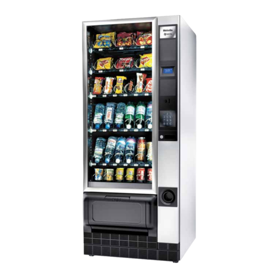
- Page 1 InstallatIon, operatIon, MaIntenance Translation of original instructions Melodia Classic english H3625EN01 2 05 - 2015 DitioN...
- Page 3 Targhetta di identificazione Identification label Valbrembo, 01/11/2014 DICHIARAZIONE DI CONFORMITA’ DECLARATION OF CONFORMITY DÉCLARATION DE CONFORMITÉ KONFORMITÄTSERKLÄRUNG DECLARACIÓN DE CONFORMIDAD DECLARAÇÃO DE CONFORMIDADE VERKLARING VAN OVEREENSTEMMING Italiano Si dichiara che la macchina, descritta nella targhetta di identificazione, è Direttive europee Sostituita da conforme alle disposizioni legislative delle Direttive Europee elencate a lato e suc- European directives...
- Page 4 Declaration of conformity Symbology The declaration of conformity with the Euro- The following symbols may be present inside the ma- pean Directives and Standards provided for by chines, according to models (signs of danger) the laws in force is supplied by the first page of Attention: dangerous voltage this manual, which is an integral part of the machine.
- Page 5 Warnings for the environment Some tricks will help you to protect the environment: This document intended for the technical personnel is - use biodegradable products to clean the machine; made available in the electronic format at the manufac- turer's (reserved area web site). - properly dispose of all the packages of the products used to fill and clean the machine;...
-
Page 9: Table Of Contents
English TablE of CoNTENTs PagE PagE INTRoDUCTIoN PRogRaMMINg identification of the machine and its features NavigatioN transport and storage programming using the vending machines of packed products positioning the vending machine fillEr mENu statistics tEcHNical fEaturEs selection prices electric energy consumption management of change tubes variable combination lock special selections... -
Page 10: Introduction
IN CasE of faIlURE In most cases, any technical problem can be solved by INTRoDUCTIoN carrying out minor operations. As a consequence, we suggest carefully reading this manual before contacting the manufacturer. The technical documentation supplied is an inte- In case of failures or malfunctions that can not be solved, gral part of the equipment and it must therefore please apply to: accompany the equipment whenever it is either... -
Page 11: Using The Vending Machines Of Packed Products
UsINg ThE vENDINg MaChINEs of PosITIoNINg ThE vENDINg MaChINE PaCkED PRoDUCTs The machine is not suitable for installation outdoors. It must be installed in a dry room and far from any The control electronics of the machine enables you to source of heat at a temperature ranging from 5°C to separately assign every single selection a different sales 34°C. -
Page 12: Technical Features
TEChNICal fEaTUREs oiN box You can also mount a cover and a lock. Height 1700 oNtrols aND safEty DEvicEs Width - payment system compartment switch Depth with glassfront open 1358 - maximum sales motor supply time Weight - compressor heat protection Supply voltage V∿... -
Page 13: Electric Energy Consumption
ElECTRIC ENERgy CoNsUMPTIoN ccEssoriEs A wide range of accessories can be mounted on the The electric energy consumption of the machine will machine to vary its performances. depend upon many factors such as the temperature and The assembly kits are supplied with mounting and test- ventilation of the room where the machine is installed, ing instructions that shall be strictly followed to preserve the product load temperature and the temperature inside... -
Page 14: Variable Combination Lock
vaRIablE CoMbINaTIoN loCk Some models are supplied with a variable combination lock. The lock is complete with a silver key, with the standard combination, for normal opening and closing operations. It is possible to customise the locks by using a kit made available as an accessory and intended to change the 0∞... -
Page 15: Filling And Cleaning
MaIN swITCh Chapter 1 If you extract the slide-in interface, a switch will power off fIllINg aND ClEaNINg the electric installation of the equipment to service and clean on fully safe conditions. The machine is not suitable for installation outdoors. It only the parts protected by covers and signalled by must be installed in a dry room at a temperature ranging the following symbol remain live inside the ma-... - Page 16 CoNTRols aND CoMPoNENTs The controls and information for the user are arranged outside the slide-in compartment. - Display: to display the credit and all operation mes- sages of the machine; - Numeric keyboard: to dispense the product, dial the number corresponding to the product you wish. Press key �...
-
Page 17: Standard Trays
sTaNDaRD TRays - dispense sticks of candies and alike. These compartments can be recognised by the pres- These trays can dispense most products. ence of a spiral complete with a divider; these spirals According to the size of products you wish to dispense, rotate just by 180°, instead by 360°, thus doubling the spirals can be housed either in 152 mm. -
Page 18: Bottle Trays
boTTlE TRays - dispense cans and bricks Cans and bricks must be positioned vertically in the These trays can be recognised by the presence of a compartments with the product raised support. retainer bridge for each compartment. Cans up to 69 mm in diameter and 0.2l bricks can be These trays enable the machine to distribute: dispensed from these compartments. -
Page 19: Loading Products
loaDINg PRoDUCTs DriNks iN bottlEs caNs aND tEtrapacks Load from the outside to the inside, vertically, with the Before loading products make sure that they have label facing the glassfront so that it can be recognised. been preserved according to the producer's in- These products may require the use of raised supports. -
Page 20: Can Trays
boTTlE / CaN TRays PowER oN Each compartment is configured to distribute different Whenever you power on the device, electronics checks products according to the spring position. the configuration of the device. If you close the machine door: To extract the tray, take it by its base; never take it by its springs or fastening brackets. -
Page 21: Cleaning At Regular Intervals
ClEaNINg aT REgUlaR INTERvals sERvICE INTERRUPTIoN The machine is to be cleaned at regular intervals; it is If the machine should remain not working for any rea- recommended to use a lukewarm water solution and non son for a long period of time, please take the following aggressive detergents. -
Page 22: Installation
Chapter 2 INsTallaTIoN Installation and any subsequent maintenance op- eration must be carried out by the personnel skilled and trained on how to use the machine as well as aware of the specific risks such a condition may involve. The machine is not suitable for installations: - outdoors, it must be installed in a dry room at a tem- perature between 5°... -
Page 23: Unpacking And Positioning
UNPaCkINg aND PosITIoNINg PayMENT sysTEM assEMbly After having unpacked the machine, make sure that the The machine is sold without any payment system. equipment is intact. as a consequence, only the installer will be liable In case of doubt never use the equipment. for any damage that may be caused to the machine No packing material (plastic bags, foam polysty- or to things and persons by an incorrect installation... -
Page 24: Electric Connection
ElECTRIC CoNNECTIoN The machine is arranged for electrical operation at a 230-240 V∿ single-phase voltage and it is protected by T6.3A fuses. For connection make sure that the rating will comply with the mains data, in particular that the supply voltage value shall lie within the limits recommended for the connec- tion points. -
Page 25: Internal Components
INTERNal CoMPoNENTs CoolINg UNIT The C.P.U. board (central process unit) is arranged in- The cooling unit is arranged at the bottom of the cabinet side the payment system compartment. It is intended to and activated by the relay board placed in the electric manage the various functions of the vending machine. -
Page 26: First Power On
fIrsT power-oN oPERaTIoN As soon as you power on the device, electronics checks NoRMal oPERaTIoN MoDE the configuration of the device. The machine is set to the normal operation mode when If you close the machine door: the machine is electrically supplied and the glassfront is - it shows the message that photocells are arranged to closed. - Page 27 DIsPlay oN TRays promotioNal mEssagE sEtup Available for some models only. Promotional messages (maximum 5) can be set and The displays on trays can show: associated with every single selection with the functions relative to the "electronic labels" of the Technician menu. - selection number As an alternative, promotional messages can be set - product code / name...
-
Page 28: Programming
NavIgaTIoN Programming Notes aCCEss To PRogRaMMINg To access the programming menus, power on the the electronics intended to control the machine will en- machine when the door is open by acting on the door able the operator to use many functions or not. switch. - Page 29 isplay kEyboarD It shows the user messages or the menu functions. NumEric kEys from To select a menu item directly by typing the correspond- ME NU T I T l E ing number shown by the summary tables in the appen- M e n u i te m dix to this manual.
-
Page 30: Filler Menu
fIllER MENU isplay The function is intended to sequence-display the same data you can obtain by printing statistics. sTaTIsTICs Press the Enter key to sequence-display the follow- ing data: The machine operation data are stored in general and relative counters that can be reset without losing total total couNtErs data. -
Page 31: Selection Prices
motor sElEctioNs sElECTIoN PRICEs To dispense long products, you can mount the dividers The machine can manage up to 4 different prices per in order to use two motors for one single selection. selection, which can be active according to the time Use this function to combine the operation of two motors band you have set (standard or promotional) and/or the by specifying the selection number and the second mo-... - Page 32 TEsT EvaDTs The EVA DTS (European Vending Association Data Est sElEctioN Transfer System) communication protocol can provide Use this function to simulate the normal dispensing for the communication between the machine and the mode of products without inserting the amount to check data transfer terminal: the operation of the spiral rotation by pressing the selec- oNNEctioN...
-
Page 33: Technician Menu
TEChNICIaN MENU xEcutivE oiN mEcHaNism vErsioN You have to choose among the following payment sys- PayMENT sysTEMs tems for the Executive system: You can decide which protocols to enable for the pay- - standard ment systems available and manage the relative func- - price holding tions.. - Page 34 aximum crEDit ispENsiNg buttoNs Use this function to define the maximum accepted credit Use this function to enable or disable the buttons ar- for inserted coins. ranged on the coin mechanism in order to discharge the coins in the change tubes. aximum cHaNgE c.p.c.
- Page 35 aximum cHaNgE You can set a limit on the total amount of the change mmEDiatE cHaNgE the coin mechanism will pay as soon as you press the The amount relative to a selection is generally cashed change button or after one single dispensing. after the machine has sent the “Successful selection”...
- Page 36 salE commaND aximum casHlEss kEy crEDit The function is used to give evidence that cash transac- Use this function to set up the maximum credit a cash- tions have occurred by means of a cashless system. less key/card may have to be accepted by the system. The values available are listed here below: If the key has got a higher value, it will be rejected.
- Page 37 NablE sElEctioNs PRICEs The function can be accessed only after the "4 price From this menu you can set up prices individually (for ranges" function has been enabled. every single selection) or globally (the same price for For every single selection you can enable or disable the all selections) and define the ranges of the promotional sale at the prices set up for each range.
-
Page 38: Vm Configuration
tEmpEraturE rEcorD vM CoNfIgURaTIoN The inner temperature is stored every 10 minutes. Use This group of functions is intended to check all param- this function to read date, time and recorded tempera- eters relative to the operation of the machine. ture atE aND timE sEt aNticoNDENsatE HEatiNg ElEmENt activatioN... - Page 39 maNagEmENt isplay This group of functions is intended to manage the basic This group of functions controls all display parameters. data of the machine operation aNguagE iNitialisatioN Use this function to select the language you wish to use This function shall be used in case of a memory data to display the machine messages among those made error or if the software is replaced.
- Page 40 ElEctroNic labEls pricE Display roDuct NamE Display The displays on the trays are arranged on some models To display the product name associated with the selec- only. tion number. The displays show the number and the price of selec- The Product name can be set up with the "Product tions;...
- Page 41 otatioN sElEctioNs cam aligNmENt Use this function to create 6 groups of several spirals To re-position the spirals that have performed an "extra" that are activated by rotation by means of the same rotation to dispense the product. selection number to increase the autonomy of the same ExEcutE Now product and to make dispensing uniform.
- Page 42 HotocEll paramEtErs ENErgy saviNg The machine can be fitted (as a standard or as an op- 2 energy saving time bands can be programmed on a tion according to the models) with a device intended to weekly basis. detect the passage of dispensed products by means of The days of the week are identified by a progressive photocells.
- Page 43 mastEr slavE moNitor The equipment is arranged for bank connection with It displays the information on a "Slave" machine, if con- other vending machines. nected. This will enable the operator to use one single payment It displays the following information: system for several machines.
- Page 44 - Photocells: If the device intended to detect the product TEsT passage is available, the light beam readout and inter- ruption are checked. This group of functions is intended to test the main com- ponents of the machine. - Compartment Lock: If the device intended to prevent the dispensing compartment from opening is available, Est sElEctioN press keys...
- Page 45 ata traNsmissioN sTaTIsTICs The function is used to select which communication in- All the machine operation data are stored in total and terface shall be used for data transmission. The following relative counters that can be reset without losing total interfaces are made available: data.
- Page 46 EsEt ElEtE rElativE statistics Statistics can be reset for relative counters either glob- Statistics can be reset either globally (all types of data) ally (all types of data) or selectively for: or selectively for: - selections - selections - discounts - discounts-overprices - failures - failures...
- Page 47 protocol auDit protocol auDit The coin mechanism data are intended to supply the fol- - Aud 1 Money in the tubes lowing information in real currency: money currently available in the change tubes - Aud 1 Money in the tubes - Aud 2 Money to the tubes money currently available in the change tubes Money conveyed to the change tubes...
- Page 48 upkEy statistics maNagEmENt CoMMUNICaTIoN -> This menu is intended to group the communication func- vENDiNg macHiNE upkEy Confirm this function after having inserted the Up key tions of the device. into the plug on the C.P.U. board to save on the up key up-kEy the statistics file with all the statistical data currently available on the vending machine.
- Page 49 - Dispensing compartment lock: faIlUREs - If the function “compartment release upon dispensing” is enabled, the fault is signalled if the closing device The machine is equipped with several sensors intended is not released and locked within a well-defined time to control the various functional units.
- Page 50 ailurE rEsEt otor statE Confirm this function to reset all current failures, if any. Use this function to learn the failure that last occurred on every single spiral even if the machine configuration otor Errors provides for an empty position. Use this function to display faulty motors for about 1 A motor can be in one of the following states: second.
-
Page 51: Maintenance
Chapter 3 MaINTENaNCE The intactness of the machine and its compliance with the standards of relevant installations must be checked by skilled personnel at least once a year. Never forget to power off the machine before car- rying out any maintenance operation requiring the disassembly of components. -
Page 52: Tray Configuration
TRay CoNfIgURaTIoN PRoDUCT EjECToR Right and left ejectors must be used for products packed PRoDUCT sPaCER in bags, such as potato crisps or alike. As they are hooked at the end of the spiral, they will push The spacers must be used to load thin products. the product further outside. -
Page 53: Product Divider
PRoDUCT DIvIDER PRoDUCT RaIsED sUPPoRT To dispense sticks of candies or alike, you can double It is recommended to use a product raised support to the 75 mm compartment capacity by using a spiral com- dispense cans or 0.2L tetrapacks. plete with a divider. -
Page 54: Tray Configuration
TRay CoNfIgURaTIoN REPlaCINg sPIRals The configuration of the spirals on each tray can be To replace the spirals, act as follows: changed. - Extract the tray in question. To shift from two single compartments to a double com- - Rotate the spiral in the direction opposite to the ejec- partment, act as follows: tion rotation while holding the plastic support flange still - Remove the tray to be modified. -
Page 55: Removing Trays
REMovINg TRays ChaNgINg ThE NUMbER of TRays To replace the tray, act as follows: To change the number of trays, act as follows: - pull the tray as far as the limit stop; - Detach the machine plug from the power mains. - detach the electrical connector from the tray;... -
Page 56: Reclining Trays
CoNfIgURaTIoN of boTTlE / CaN REClININg TRays TRays Spiral trays are complete with a leverage system that enables the operator to recline them to the bottom to The trays for bottles can be configured to dispense 0.5 l / facilitate the load cycle. 0.6 l and 0.33 l plastic bottles as well as 0.33, 0.375 and Just lock the leverage system by means of a screw in the 0.25 l "slim"... -
Page 57: Refrigerated Box Configuration
REfRIgERaTED boX ClEaNINg ThE vENTIlaTIoN gRIDs of ThE CoolINg sysTEM CoNfIgURaTIoN Clean the ventilation grids of the cooling system at least Cold air is dispensed from the grid at the back of the every 30 days. refrigerated box (behind the trays). after detaching the machine from the mains, act as fol- The machine is supplied with a shutter intended to vary lows:... -
Page 58: Board Functions
boaRD fUNCTIoNs CPU boaRD The CPU board is arranged on the slide-in shelf of pay- ment systems and intended to manage all components of the machine. The LEDs on the board can supply the following informa- tion during the operation: - the green LED (26) is flashing on and off during the normal operation of the C.P.U. -
Page 59: Electric Panel
glassfRoNT lIghTINg boaRD ElECTRIC PaNEl This board is intended to supply the glassfront lighting The electric panel is accommodated in the compartment LED’s for constant brightness. of payment systems. The door switch can be directly The board is arranged in the slide-in shelf of payment accessed. -
Page 60: Access To The Cooling Unit
aCCEss To ThE CoolINg UNIT If you have to access the cooling unit from the machine for any reason whatsoever, please act as follows: - Remove the last drawer from the machine temporarily - Remove the vandal-proof grid from the dispensing compartment - Remove the feet cover;... - Page 61 appendix © by N&W GLOBAL VENDING S.p.A. 05-2015 3625 01...
- Page 62 Salim 1 2 3 4 5 7 6 5 4 3 1 2 3 4 5 3 2 1 1 2 3 1 2 3 4 5 6 7 8 9 T6,3A 230V 24V-4A is drawing contains confidential information and is the property of the holding company of N&W or one of its subsidiaries,without whose permission it may not be...
- Page 63 Melodia SCHEMA ELETTRICO - WIRING DIAGRAM RIPAMONT CAPOBIANCO 24/05/2010 SCHEMA ELETTRICO Classic LEGENDA PART NUMBER VERSION 608602601 MELODIA CLASSIC COMPRESSOR RS232 SERIAL PORT MVT MOTOR -DRIVEN FAN SALIM POWER SUPPLY UNIT BOARD TEMPERATURE PROBE BUTTON BOARD PROGRAMMING BUTTON C.P.U. BOARD HEATING ELEMENT TRANSFORMER R1-...
- Page 64 CASSETTI/ is drawing contains confidential information and is the property of the holding company of N&W or one of its subsidiaries,without whose permission it may not be copiedor discosed to third parties of otherwise used. This drawing has to be returned promptly upon request to N&W.
- Page 65 SSETTI/TRAYS Slcd1 0(23) 0(21) Slcd6 0(22) J13-14 0(25) 0(26) MODEL DEFINITION DATE SHEET PREPARED CHECKED Melodia SCHEMA ELETTRICO - WIRING DIAGRAM RIPAMONTI CAPOBIANCO 25/05/2010 SCHEMA ELETTRICO VASSOI TRAYS LEGENDA PART NUMBER VERSION 608602701 MELODIA...
- Page 66 ___________________________________________ ___________________________________________ ___________________________________________ ___________________________________________ ________________________________________________ ________________________________________________ ________________________________________________ ________________________________________________ ________________________________________________ ________________________________________________ ________________________________________________ ________________________________________________ ________________________________________________ ________________________________________________ ________________________________________________ ________________________________________________ ________________________________________________ ________________________________________________ ________________________________________________ ________________________________________________ ________________________________________________ ________________________________________________ ________________________________________________ ________________________________________________ ________________________________________________ ________________________________________________ ________________________________________________ ________________________________________________ ________________________________________________...
- Page 67 The Manufacturer reserves the right to modify the features of the equipment described in this publication without giv- ing any prior notice. Moreover, it disclaims all responsibility for any inaccuracy contained in this publication that can be ascribed to printing and/or transcription errors. All instructions, drawings, tables and information in general contained in this publication are confidential and can be neither entirely nor partially reproduced or transmitted to third parties without the written consent of the Manufacturer who has the sole ownership.
Need help?
Do you have a question about the Melodia Classic and is the answer not in the manual?
Questions and answers