Table of Contents
Advertisement
Quick Links
Advertisement
Table of Contents

Subscribe to Our Youtube Channel
Related Manuals for Moxa Technologies CA-132/132I


Summary of Contents for Moxa Technologies CA-132/132I
- Page 1 CA-132/132I User’s Manual Third Edition, November 2004 www.moxa.com/product Moxa Technologies Co., Ltd. Tel: +886-2-8919-1230 Fax: +886-2-8919-1231 Web: www.moxa.com MOXA Technical Support Worldwide: support@moxa.com.tw The Americas support@moxa.com...
-
Page 2: Copyright Notice
Information provided in this manual is intended to be accurate and reliable. However, Moxa Technologies assumes no responsibility for its use, or for any infringements on the rights of third parties that may result from its use. -
Page 4: Table Of Contents
Product Features... 1-2 Product Specifications... 1-2 Chapter 2 Hardware Installation...2-1 Hardware Installation ... 2-2 Block Diagram of CA-132/132I... 2-2 RS-422/485 Interface Settings ... 2-3 I/O Base Address & Interrupt Vector Settings ... 2-3 IRQ Setting... 2-5 Initial Inspection ... 2-5 RS-422/485 Pin Assignments ... -
Page 5: Chapter 1 Introduction
Both ports of CA-132/132I can be configured by DIP Switch for either the RS-422 or RS-485 interface, and with its PC/104 standard, the CA-132/132I Series is compatible with any PC/104 CPU module or CPU card that accepts PC/104 expansion modules. -
Page 6: Overview
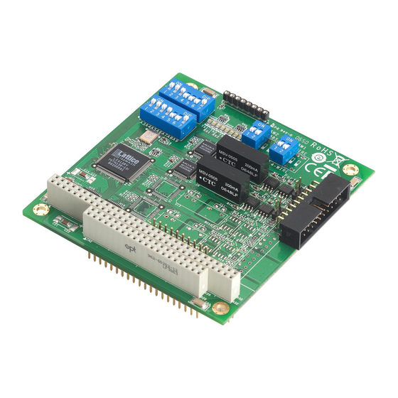
Overview CA-132/132I is a PC/104 module that supports the RS-422/485 serial interfaces, and can be used with PC/104 CPU modules or CPU cards that accept PC/104 expansion modules. CA-132/132I has two independent serial interfaces, which are accessed through RJ45 connectors. You can configure both ports for the RS-422 or RS-485 interfaces by DIP switch. - Page 7 Introduction ! Storage temperature: -20 to 85℃ ! Relative humidity: 5 to 95%, non-condensing ! Regulatory Approvals: FCC Class A, CE CA-132/132I User’s Manual...
-
Page 9: Chapter 2 Hardware Installation
This chapter includes information about hardware installation of CA-132/132I Series boards. The following topics are covered: Hardware Installation Block Diagram of CA-132/132I RS-422/485 Interface Settings I/O Address & Interrupt Vector Settings IRQ Setting Initial Inspection RS-422/485 pin assignments Hardware Installation... -
Page 10: Hardware Installation
Hardware Installation The hardware installation of CA-132/132I serial boards is easy to carry out. Before you insert CA-132/132I into the PC/104 interface, you must first configure the RS-422/485 setting, I/O Base Address & Interrupt Vector, and IRQ Settings. Follow the detailed steps given below to install the CA-132/132I serial board in your computer. -
Page 11: Rs-422/485 Interface Settings
I/O Base Address & Interrupt Vector Settings CA-132/132I Series have two 7-switch DIP switch panels, named SW1 and SW2. Panel SW1 is for I/O Base Address setting, and SW2 is for Interrupt Vector setting. Once you configure Port 1’s I/O Base Address and Interrupt Vector, the settings for the other ports will be configured automatically as well. - Page 12 180, and the INT Vector is configured to be 1C0. The diagram shown above is SW1 for setting I/O Base Address. CA-132/132I User’s Manual The diagram shown above is SW2 for setting INT Vector. 0 × 180...
-
Page 13: Irq Setting
CA-132/132I Series has a jumper selectable function for you to configure IRQ settings. Before you insert a CA-132/132I board into the PC/104 interface, you need to choose an available jumper from 3, 4, 5, 6, 7, 9, 10, 11, 12, or 15 to configure the IRQ setting. -
Page 14: Rs-422/485 Pin Assignments
RS-422/485 Pin Assignments Async Port 4-wire RS-422/4-wire 485 Pin Assignment (RJ45) SIGNAL TXD+ TXD- RXD- RXD+ Async Port 2-wire RS-485 Pin Assignment (RJ45) SIGNAL DATA- DATA+ CA-132/132I User’s Manual... -
Page 15: Chapter 3 Software Installation
After installing the CA-132/132I serial boards in your computer, the next step is to install the software. The drivers for CA-132/132I support various operating systems, including Window NT, Windows 2000/XP/2003, and Windows 95/98/Me. This chapter includes information about how to install and remove the CA-132/132I board. -
Page 16: Windows Nt
Windows NT Installing the driver The following procedure is for installing the CA-132/132I serial board driver under Windows NT 4.0. Use the mouse to position the cursor over your desktop’s Network icon, and then click the right mouse button. Select Properties and then click the left mouse button. - Page 17 When the Select Network Adapter window opens, click on Have Disk to install the driver from the floppy disk enclosed with the CA-132/132I serial board. The Insert Disk window will open asking you to insert the disk into your computer. Type A:\windows.nt to locate the setup file on the disk and then click OK.
- Page 18 When the Property window opens, select CA132 Series or CA132I Series under Board Type. The window will show the COM port number to which the serial ports of CA-132/CA-132I are assigned, and the default settings for the ports. Click OK to continue. CA-132/132I User’s Manual...
- Page 19 The Network window will open, showing the serial board you just added to your computer. Click OK to finish the installation. Removing a CA-132/132I serial board If you wish to remove a CA-132/132I serial board, move your mouse to your desktop’s Network icon, click the right mouse button, and then select Properties. CA-132/132I User’s Manual...
-
Page 20: Windows 2000/Xp/2003
When the Network window opens, choose Adapters, select MOXA PC104 Communication Module Adapter, and then click on Remove. A Warning window will open. Click Yes if you wish to remove the CA-132/132I serial board. Windows 2000/XP/2003 Installing the driver The following procedure explains how to install the CA-132/132I serial board driver under Windows 2000/XP/2003. - Page 21 When the System Properties window opens, click on the Hardware tab, and then click on Hardware Wizard… to start the installation. The Add/Remove Hardware Wizard window will open next. Click on Next to continue. CA-132/132I User’s Manual...
- Page 22 When the Choose a Hardware Task window opens, select Add/Troubleshoot a device, and then click on Next to continue. The New Hardware Detection window will open showing that the Wizard is searching for the CA-132/CA-132I serial board on your computer. CA-132/132I User’s Manual...
- Page 23 Next to continue. The Find New Hardware window will open next. Select No, I want to select the hardware from a list, since CA-132/132I is a brand new type of ISA serial board, and then click on Next to continue.
- Page 24 When the Hardware Type window opens, select Multi-port serial adapters under Hardware types, and then click on Next to continue. When the Select a Device Driver window opens, click on Have Disk to install the CA-132/132I driver from the floppy disk that came with the CA-132/132I serial board.
- Page 25 12. When the Select a Device Driver window opens, select MOXA CA132 Series or MOXA CA132I Series and then click Next to continue. 13. The Start Hardware Installation window will open next. Click on Next to continue. CA-132/132I User’s Manual 3-11...
- Page 26 15. The next window to open states that the installation is completed. Click Finish to end the installation. 16. After the installation is completed, use your mouse to position the cursor over your desktop’s My Computer icon, click the right mouse button, and then select Properties. 3-12 CA-132/132I User’s Manual...
- Page 27 18. The Device Manager window will open next. At this point, you should be able to find MOXA CA132 Series/MOXA CA132I Series under Multi-port serial adapters, and MOXA communication Port 1 and Port 2 (assigned to COM 15 and COM 16, respectively, for the example shown here) under Ports (COM & LPT). CA-132/132I User’s Manual 3-13...
- Page 28 Ports Configuration, Driver version, and Resource Settings. Disabling the device Use your mouse to position the cursor over you desktop’s My Computer icon, click the right mouse button, and then select Properties. 3-14 CA-132/132I User’s Manual...
- Page 29 The Device Manager window will open. Select MOXA CA132 Series/MOXA CA132I Series under Multi-port serial adapters, and click on the right mouse button. Select Disable and click on the left mouse button to disable the device. CA-132/132I User’s Manual 3-15...
-
Page 30: Windows 95/98/Me
Windows 95/98/ME Installing the driver The following is for installing the driver of CA-132/132I serial boards under Windows 95/98/ME. Insert the installation disk into your computer. Click on Run under the Start Menu, and then click on Browse to locate the setup file in the disk, or directly type in the path. - Page 31 A window will open stating the computer is ready to install the driver. Click on Next to continue. A message will appear showing that the setup file is being installed. A window will appear showing that the installation is completed. Click on Finish to end the installation. CA-132/132I User’s Manual 3-17...
- Page 32 The Moxa PC104 Communication Module Configuration Panel window will appear. Click on Add to add the CA-132/132I serial board to your computer. The Property window will open. Select CA132 Series/CA132I Series under Board Type. 3-18 CA-132/132I User’s Manual...
- Page 33 The Property window will show the COM port number to which the serial ports of CA-132/132I are assigned, and the default settings of the ports. Click OK to continue. The Moxa PC104 Communication Module Configuration Panel window will show the CA132/CA132I serial board you just added.
- Page 34 Property to see and configure the information and settings of the board’s COM ports. Removing the device If you wish to remove the device, follow steps 11 and 12 of Installing the driver. Click on Remove when the Moxa PC104 Communication Module Configuration Panel opens. 3-20 CA-132/132I User’s Manual...
-
Page 35: Uninstalling The Driver
A warning message will appear asking you if you really want to remove this board. Click on Yes to remove the CA-132/132I serial board. Uninstalling the driver Click on Start " Settings " Control Panel. Select Add/Remove Programs. Choose Install/Uninstall, select MOXA PC104 Communication Module Driver, and then click Add/Remove to uninstall the driver. -
Page 36: Dos
For details of the serial programming (API-232 Library) and utilities, please refer to the next chapter, “Serial Programming Tools”. Installing Driver Run the installation program, DOSINST.EXE, in the DOS folder. Specify the target API-232 directory (e.g. C:\MOXA) where software driver will be copied. Press F2 to start the installation. 3-22 CA-132/132I User’s Manual... -
Page 37: Driver Setup
Please refer to the F1 on-line help instructions as running setup program. Run the setup program, BIN\SETUP.EXE. Please press Enter to select the proper model name, CA-132 Series. If you install CA-132I model, select CA-132I Series. CA-132/132I User’s Manual 3-23... - Page 38 4 if you need not change any setting or configure any board. You may now enter/modify each port’s configuration. These displayed values are the port initial values as driver is loaded. Legend: 3-24 CA-132/132I User’s Manual Some noticeable fields and functions are explained below.
- Page 39 RxD buffer size: The receiving (input) buffer allocated in the system for each port. F5: Group Edit: This is a convenient function that helps you edit the configuration of several ports at one time as a group. Press F10 to save the latest configuration and exit the SETUP program. CA-132/132I User’s Manual 3-25...
-
Page 40: Loading Driver
It means the CA-132 Series driver is installed properly. At this point, you are ready to execute application that supports API-232 functions, or start developing applications using API-232 library. Unloading Driver To unload (release) the CA-132 Series driver from memory, type “DPC-DRV/Q” at the DOS prompt. 3-26 CA-132/132I User’s Manual... -
Page 41: Serial Programming Tool
Chapter 4 Moxa supports a class of easy to use, yet powerful serial programming libraries and communication troubleshooting utilities under Windows NT/2000/XP/2003 and Windows 95/98/Me. Use these MOXA Serial Programming Tools to decrease your software development time. In the following sections, we describe the installation of the library, and the utilities supported for various programming platforms. -
Page 42: Pcomm Installation
A convenient diagnostic program, ONLY for MOXA boards and ports, provides internal and external testing of IRQ, TxD/RxD, UART, CTS/RTS, DTR/DSR, DTR/DCD, etc. It allows the user to check the function of both software and hardware. To run the Diagnostic program, click on [Start]"[Program]"[PComm Lite]"[Diagnostic]. CA-132/132I User’s Manual... - Page 43 Terminal Emulator features multi-windows, and supports VT100 and ANSI terminal types. You can transfer data interactively, send patterns periodically, and transfer files using ASCII, XMODEM, YMODEM, ZMODEM, and KERMIT protocols. To run Terminal Emulator, click on [Start]"[Program]"[PComm Lite]"[Terminal Emulator]. CA-132/132I User’s Manual...
-
Page 44: Rs-485 Programming
This mode should be compatible with most existing RS-485 applications. How to transmit and receive data for Windows NT, 95/98 We recommend you to configure CA-132/132I Series ports as follows in order to acquire precise timing control in RS-485 2-wire transmission. There are 2 solutions to control RS-485 2-wire transmission. -
Page 45: Appendix A Service Information
This appendix shows you how to contact Moxa for information about this and other products, and how to report problems. In this appendix, we cover the following topics. MOXA Internet Services Problem Report Form Product Return Procedure Service Information Appendix A... -
Page 46: Moxa Internet Services
Moxa Internet Services has been set up to provide technical support, driver updates, product information, and user’s manual updates. E-mail for technical support World Wide Web (WWW) Site for product information: CA-132/132I User’s Manual The following services are provided ...support@moxa.com.tw ...http://www.moxa.com... -
Page 47: Problem Report Form
Problem Description: Please describe the symptoms of the problem as clearly as possible, including any error messages you see. A clearly written description of the problem will allow us to reproduce the symptoms, and expedite the repair of your product. Fax: Date: $ CA-132I CA-132/132I User’s Manual A-3... -
Page 48: Product Return Procedure
Carefully pack the product in an anti-static package, and send it, pre-paid, to the dealer. The PRA should be visible on the outside of the package, and include a description of the problem, along with the return address and telephone number of a technical contact. CA-132/132I User’s Manual... -
Page 49: Revision History
Changed Moxa’s new logo on the title page. p.1-2 Changed power consumption. Added Regulatory Approvals. p.2-2 Changed block diagram. p.2-6 Changed “Async Port 4-wire RS-422 Pin Assignment (RJ45)” to “Async Port 4-wire RS/422/485 Pin Assignment (RJ45).” CA-132/132I User’s Manual A-5 Revision Details...
Need help?
Do you have a question about the CA-132/132I and is the answer not in the manual?
Questions and answers