Table of Contents
Advertisement
Quick Links
Advertisement
Table of Contents

Related Manuals for Moxa Technologies CA Series


Summary of Contents for Moxa Technologies CA Series
- Page 1 CA Series PC/104 Multiport Serial Module User’s Manual www.moxa.com/product Third Edition, May 2007 Moxa Technologies Co., Ltd. Tel: +886-2-8910-1230 Fax: +886-2-8910-1231 Web: www.moxa.com Moxa Technical Support Worldwide: support@moxa.com The Americas support@usa.moxa.com...
- Page 2 CA Series PC/104 Multiport Serial Module User’s Manual The software described in this manual is furnished under a license agreement and may be used only in accordance with the terms of that agreement. Copyright Notice Copyright © 2007 Moxa Technologies Co., Ltd.
-
Page 3: Table Of Contents
Table of Contents Chapter 1 Introduction ....................1-1 Overview ..........................1-2 Package Checklist......................... 1-2 Product Features ........................1-2 Product Specifications ......................1-3 Chapter 2 Hardware Installation ................2-1 Hardware Installation ......................2-2 Block Diagrams ........................2-2 I/O Base Address ......................2-4 Interrupt Vector ......................2-5 Serial Interface...................... - Page 4 Chapter 4 Serial Programming Tools................4-1 Serial Programming Library....................4-2 PComm Utilities ........................4-2 Installation ........................4-2 PComm Diagnostic....................... 4-2 PComm Monitor ......................4-3 PComm Terminal Emulator..................4-4 Chapter 5 Pin Assignments ..................5-1 Box Header Pin Assignments ....................5-1 RS-232.......................... 5-1 RS-422, 4-wire RS-485 ....................
-
Page 5: Chapter 1 Introduction
Introduction Chapter 1 Welcome to the CA Series of PC/104 communication modules, a multiport serial module for industrial applications. It is designed for PC/104 CPU boards that accept the PC/104 expansion interface. Optional DB9 and DB25 cables are available to connect different devices. The device drivers make full use of the 64-byte Tx/Rx FIFO and on-chip flow control, which allows up to 921.6 Kbps data transmission. -
Page 6: Overview
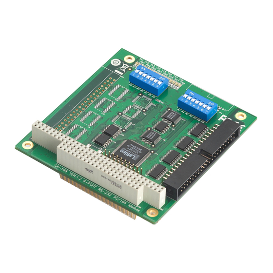
Introduction Overview The CA Series PC/104 module is designed to be used with PC/104 CPU modules or CPU cards with the PC/104 expansion interface. Models are available for RS-232, RS-422, and RS-485, with 2, 4, or 8 ports. The serial ports are accessed through a 20 or 40-pin box header connector on the module. -
Page 7: Product Specifications
CA Series User’s Manual Introduction Product Specifications CA Series PC/104 Multiport Serial Module Hardware I/O controller 16C550C or compatible Connector Type 40-pin box header (CA-108, CA-114, CA-134I, CA-104 V2) 20-pin box header (CA-132 V2, CA-132I V2) Interface PC/104 bus (Ver. 2.4) No. - Page 8 CA Series User’s Manual Introduction Other Dimensions (W x D) 96 x 90 mm Regulatory Approvals EN55022 Class A, EN55024, EN6100-3-2, EN61000-3-3, FCC Part 15 Class A Warranty 5 years...
-
Page 9: Chapter 2 Hardware Installation
Hardware Installation Chapter 2 This chapter explains how to install the CA Series PC/104 multiport serial module. The following topics are covered: Hardware Installation Block Diagrams I/O Base Address Interrupt Vector Serial Interface... -
Page 10: Hardware Installation
CA Series User’s Manual Hardware Installation Hardware Installation Installing the CA Series module is easy. Before inserting the module into the PC/104 slot, you must first configure the I/O base address, interrupt vector, IRQ, and serial interface (for select models). - Page 11 CA Series User’s Manual Hardware Installation CA-114 Serial Interface SW1: I/O Base Address SW2: Interrupt Vector PC/104 Slot Box Header Connector CA-134I, CA-132 V2, CA-132I V2 RS-422/RS-485 2-WIRE/4-WIRE SW1: I/O Base Address SW2: Interrupt Vector PC/104 Slot Box Header Connector...
-
Page 12: I/O Base Address
CA Series User’s Manual Hardware Installation I/O Base Address Use DIP switch SW1 to set port 1’s I/O base address. The other ports will be configured automatically. The default I/O base address is 0×180 and allows settings from 0×000 to 0×3FF. -
Page 13: Interrupt Vector
CA Series User’s Manual Hardware Installation Interrupt Vector Use DIP switch SW2 to set port 1’s interrupt vector. The default interrupt vector is 0×1C0, with SW2 set as follows: 0×1C0 A3 A4 A5 A6 A7 A8 A9 = on, = off... -
Page 14: Chapter 3 Software Installation
Software Installation Chapter 3 After installing the CA Series module in your embedded computer, the next step is installing the software. Drivers for various operating systems are provided, including DOS, Windows, and Linux. This chapter explains how to install and remove the CA Series driver. -
Page 15: Windows Vista (32-Bit)
Windows Vista (32-bit) The Windows Vista (32-bit) drivers conform to the Win32 COMM API standard and support all models in the CA Series. In the following instructions, the CA-114 is used as an example. Installing the Driver 1. After turning the embedded computer on, log into Windows as Administrator. - Page 16 CA Series User’s Manual Software Installation 5. The Add Hardware Wizard will open. Click Next to continue. 6. Select Install the hardware that I manually select from a list (Advanced) and click Next to continue.
- Page 17 CA Series User’s Manual Software Installation 7. Select Multi-port serial adapters and click Next to continue. 8. Click Have Disk. 9. For 32-bit (x86) platforms, select the \CA Series\Software\Windows Vista\x86 folder on the CD and click OK to continue.
- Page 18 CA Series User’s Manual Software Installation 10. Select your CA Series model and click Next to continue.
- Page 19 CA Series User’s Manual Software Installation 11. If you see a warning that the software has not passed Windows Logo testing, click Install this driver software anyway. 12. After the files have been installed, click Finish.
- Page 20 CA Series User’s Manual Software Installation 13. After the module is installed, you will be prompted to install the new serial ports. A Found New Hardware Wizard window will open for the first serial port, port 0. Select Locate and...
- Page 21 CA Series User’s Manual Software Installation 14. Select I don’t have the disc. Show me other options. 15. Select Browse my computer for driver software (advanced).
- Page 22 CA Series User’s Manual Software Installation 16. For 32-bit (x86) platforms, select the \CA Series\Software\Windows Vista\x86 folder on the CD and click OK to continue. 17. Windows will install the driver software.
- Page 23 CA Series User’s Manual Software Installation 18. If you see a warning that the software has not passed Windows Logo testing, click Install this driver software anyway. 19. After the files have been installed, click Close. The remaining serial ports will automatically install in the background.
-
Page 24: Using Device Manager To Verify Installation
Software Installation Using Device Manager to Verify Installation You can use Windows Device Manager to verify proper installation of the CA Series module. In the following instructions, the CA-114 is used as an example. 1. Under My Computer, click System Properties. -
Page 25: Port Configuration
Windows event log for details. Port Configuration After the driver is installed, a CA Series Properties window will appear. The system will map the serial ports automatically. It will prompt you to take care of port configuration if another CA Series module has been installed on the PC. - Page 26 4. Select a Tx FIFO Size. The default value is 64 bytes (high level). Select Set the change to all ports to use this setting for all serial ports on the module. 5. Click OK to approve the port settings. Click OK again to close the CA Series Properties window and apply the new port settings.
-
Page 27: Windows Xp, 2003 (32-Bit)
Windows XP, 2003 (32-bit) The Windows XP and 2003 (32-bit) drivers conform to the Win32 COMM API standard and support all models in the CA Series. In the following instructions, the CA-114 is used as an example. Installing the Driver 1. - Page 28 CA Series User’s Manual Software Installation 3. Select Add a new hardware device and click Next to continue. 4. Select Install the hardware that I manually select from a list (Advanced) and click Next to continue. 3-15...
- Page 29 CA Series User’s Manual Software Installation 5. Select Multi-port serial adapters and click Next to continue. 6. Click Have Disk. 3-16...
- Page 30 7. You will be prompted to insert the installation disk. Insert the Document and Software CD into the CD-ROM drive and select the \CA Series\Software\Windows XP_2003\x86 folder on the CD. Click OK to continue. 8. Select your CA Series model and click Next to continue. 3-17...
- Page 31 CA Series User’s Manual Software Installation 9. To begin installing the module, click Next. 10. If you see a warning that the software has not passed Windows Logo testing, click Continue Anyway. 11. Windows will install the drivers. When the installation is complete, click Finish.
- Page 32 CA Series User’s Manual Software Installation 12. After the module is installed, you will be prompted to install the new serial ports. A Found New Hardware Wizard window will open for the first serial port, port 0. Select No, not this time and click Next.
- Page 33 13. Select Install from a list or specific location (Advanced) and click Next. 14. Select Search for the best driver in these locations and Include this location in the search. Select the \CA Series\Software\Windows XP_2003\x86 folder on the CD and click Next. 3-20...
- Page 34 CA Series User’s Manual Software Installation 15. If you see a warning that the software has not passed Windows Logo testing, click Continue Anyway. 16. Windows will install the necessary drivers. 3-21...
-
Page 35: Using Device Manager To Verify Installation
18. Repeat the installation process for the remaining serial ports. Using Device Manager to Verify Installation You can use Windows Device Manager to verify proper installation of the CA Series module. In the following instructions, the CA-114 is used as an example. - Page 36 CA Series User’s Manual Software Installation 2. In the Hardware tab, click Device Manager. 3. In the Device Manager window, you should see your CA Series module under Multi-port serial adapters. You should also see MOXA communication ports under Ports (COM & LPT).
-
Page 37: Port Configuration
Software Installation Port Configuration After the driver is installed, a CA Series Properties window will appear. The system will map the serial ports automatically. It will prompt you to take care of port configuration if another CA Series module has been installed on the PC. -
Page 38: Using Pcomm
CA Series User’s Manual Software Installation 5. Click OK to approve the port settings. Click OK again to close the CA Series Properties window and apply the new port settings. Using PComm PComm Diagnostic is a useful program for checking the module’s status. It provides internal and external testing of IRQ, TxD/RxD, UART, CTS/RTS, DTR/DSR, and other items. -
Page 39: Disabling The Module
CA Series User’s Manual Software Installation Disabling the Module 1. Right-click My Computer and select Properties in the context menu. 2. In the Hardware tab, click Device Manager. 3. In Device Manager, right-click your module under Multi-port serial adapters and select Disable in the context menu. -
Page 40: Uninstalling The Module
CA Series User’s Manual Software Installation Uninstalling the Module 1. Right-click My Computer and select Properties in the context menu. 2. In the Hardware tab, click Device Manager. 3-27... - Page 41 CA Series User’s Manual Software Installation 3. Right-click your module under Multi-port serial adapters and select Uninstall in the context menu. 4. A confirmation dialog will appear. Click OK to uninstall the device. 3-28...
-
Page 42: Windows 2000
Windows 2000 The Windows 2000 drivers conform to the Win32 COMM API standard and support all models in the CA Series. In the following instructions, the CA-114 is used as an example. Installing the Driver 1. Open Add/Remove Hardware in the Control Panel. - Page 43 CA Series User’s Manual Software Installation 3. Select Add/Troubleshoot a device and click Next. 4. Windows will search for new hardware. 3-30...
- Page 44 CA Series User’s Manual Software Installation 5. When the search is complete, select Add a new device and click Next to continue. 6. Select No, I want to select the hardware from a list and click Next to continue. 3-31...
- Page 45 CA Series User’s Manual Software Installation 7. Select Multi-port serial adapters and click Next to continue. 8. Click Have Disk. 9. You will be prompted to insert the installation disk. 3-32...
- Page 46 CA Series User’s Manual Software Installation Insert the Document and Software CD into the CD-ROM drive and select the \CA Series\Software\Windows 2K folder on the CD. Click OK to continue. 10. Select your CA Series model and click Next to continue. 3-33...
- Page 47 CA Series User’s Manual Software Installation 11. To begin installing the module, click Next. 12. If you see a warning that the Microsoft digital signature was not found, click Yes to proceed with the installation. 3-34...
- Page 48 CA Series User’s Manual Software Installation 13. Windows will install the drivers. When the installation is complete, click Finish. 14. After the module is installed, you will be prompted to install the new serial ports. A Found New Hardware Wizard window will open for the first serial port, port 0. Click Next to proceed.
- Page 49 CA Series User’s Manual Software Installation 15. Select Search for a suitable driver for my device [recommended] and click Next. 16. Select Specify a location and click Next. 17. Select the \CA Series\Software\Windows 2K folder on the CD and click Next. 3-36...
- Page 50 CA Series User’s Manual Software Installation 18. When the driver has been found, click Next to proceed. 19. Windows will install the necessary drivers. After the installation is complete, click Finish. The remaining serial ports will be installed automatically in the background.
-
Page 51: Using Device Manager To Verify Installation
Software Installation Using Device Manager to Verify Installation You can use Windows Device Manager to verify proper installation of the CA Series module. In the following instructions, the CA-114 is used as an example. 1. Right-click My Computer and select Properties in the context menu. - Page 52 CA Series User’s Manual Software Installation 3. In the Device Manager window, you should see your CA Series module under Multi-port serial adapters. You should also see MOXA communication ports under Ports (COM & LPT). 4. If you see any special marks, such as a question mark or an exclamation mark, next to the MOXA items, the installation of your module or serial ports was not successful.
-
Page 53: Port Configuration
Software Installation Port Configuration After the driver is installed, a CA Series Properties window will appear. The system will map the serial ports automatically. It will prompt you to take care of port configuration if another CA Series module has been installed on the PC. -
Page 54: Using Pcomm
4. Select a Tx FIFO Size. The default value is 64 bytes (high level). Select Set the change to all ports to use this setting for all serial ports on the module. 5. Click OK to approve the port settings. Click OK again to close the CA Series Properties window and apply the new port settings. -
Page 55: Disabling The Module
CA Series User’s Manual Software Installation Disabling the Module 1. Right-click My Computer and select Properties in the context menu. 2. In the Hardware tab, click Device Manager. 3. In Device Manager, right-click your module under Multi-port serial adapters and select Disable in the context menu. - Page 56 CA Series User’s Manual Software Installation 2. In the Hardware tab, click Device Manager. 3. Right-click your module under Multi-port serial adapters and select Uninstall in the context menu. 3-43...
- Page 57 CA Series User’s Manual Software Installation 4. A confirmation dialog will appear. Click OK to uninstall the device. 3-44...
-
Page 58: Windows Nt
CA Series User’s Manual Software Installation Windows NT The Windows NT drivers conform to the Win32 COMM API standard and support the CA-104 V2, CA-104-T V2, CA-132 V2, CA-132-T V2, CA-132I V2, and CA-132I-T V2. The CA-108, CA-114, and CA-134I models are not supported under Windows NT. - Page 59 CA Series User’s Manual Software Installation 3. When prompted to select a network adapter, click Have Disk. 4. At the prompt, insert the installation disk provided with your module. For the location, enter A:\windows.nt. Click OK to continue. 5. Windows will install the drivers.
- Page 60 6. After the files have been installed, a configuration panel will open. Click Add to continue. 7. Under Board Type, select your CA Series model. The window will show the COM port numbers that will be assigned to the CA Series serial ports, as well as other settings. Click OK to continue.
- Page 61 CA Series User’s Manual Software Installation 8. The CA Series module will appear as a network adapter. Click OK to complete installation of the module. 3-48...
-
Page 62: Uninstalling The Module
Uninstalling the Module 1. Right-click Network Neighborhood and select Properties in the context menu. 2. In the Adapters tab, select your CA Series module and click Remove. 3. A confirmation dialog will appear. Click OK to uninstall the device. 3-49... -
Page 63: Windows 95, 98, Me
CA-108, CA-114, and CA-134I models are not supported under Windows 95, 98, or ME. In the following instructions, the CA-104 is used as an example. Installing the Driver 1. Insert the CA Series installation disk and run Setup95.exe through Start menu Run. 2. Click Next to proceed through the welcome screens. - Page 64 CA Series User’s Manual Software Installation 3. Windows will install the drivers. When the installation is complete, click Finish. 4. After the files have been installed, a configuration panel will open. Click Add to continue. 3-51...
- Page 65 Software Installation 5. Under Board Type, select your CA Series model. The window will show the COM port numbers that will be assigned to the CA Series serial ports, as well as other settings. Click OK to continue. 6. The CA Series module will now appear in the configuration panel. Click OK to complete installation of the module.
-
Page 66: Uninstalling The Module
Programs Moxa Utilities MOXA PC104 Communication Module Configuration Panel. Select your CA Series module and click Remove. 2. A confirmation dialog will appear. Click Yes to uninstall the device. 3. To remove the driver from the system, open Add/Remove Programs in the Control Panel. - Page 67 CA Series User’s Manual Software Installation 4. In the Install/Uninstall tab, select MOXA PC104 Communication Module Driver and click Add/Remove. 5. A confirmation dialog will appear. Click Yes to remove the driver. 6. After the driver is removed, click OK to close the window.
-
Page 68: Linux
CA Series User’s Manual Software Installation Linux 1. Execute the following commands from the Linux prompt: #mount /dev/cdrom /mnt/cdrom #cd / #mkdir moxa #cd moxa #cp /mnt/cdrom/<driver directory>/mxpcdrv.tgz . #tar xvfz mxpcdrv.tgz 2. #cd mxpcdrv # make clean; make install 3. -
Page 69: Dos
CA Series User’s Manual Software Installation MOXA DOS API-232 is a software package that can help you develop or debug serial communications programs. This section will explain how to install the package, set up the driver, and load or unload the driver. For additional information about the API-232 library and utilities, please refer to Chapter 4. -
Page 70: Driver Setup
F1 in the setup program. 1. Run the setup program, BIN\SETUP.EXE. 2. Select your CA Series model and press Enter. 3. You must set the Port No., I/O Address, IRQ and INT Vector properly. These settings must match your module’s hardware configuration. - Page 71 CA Series User’s Manual Software Installation This is the port ID of each port. Application software will refer to a port Port number: by its port number (ID). Port numbers must be unique; duplicate port numbers are not allowed. The port ID can range from 0 to 127 as long as it does not overlap with another port.
-
Page 72: Loading The Driver
Device driver setup O.K. At this point, you can execute applications that support API-232 functions, or start developing applications using the API-232 library. Unloading the Driver To unload or release the CA Series driver from memory, enter DPC-DRV/Q at the DOS prompt. 3-59... -
Page 73: Serial Programming Tools
Serial Programming Tools Chapter 4 MOXA provides Windows serial programming libraries and troubleshooting utilities that are easy to use and powerful. You can use these tools to reduce software development time. The serial communication library is useful for developing applications for data communications, remote access, data acquisition, and industrial control. -
Page 74: Serial Programming Library
CA Series User’s Manual Serial Programming Tools Serial Programming Library The serial programming library assists you in developing serial communications programs for any COM port that complies with the Microsoft Win32 API. It facilitates the implementation of multi-process and multi-thread serial communication programs and can remarkably reduce development time. -
Page 75: Pcomm Monitor
CA Series User’s Manual Serial Programming Tools PComm Monitor PComm Monitor is designed for MOXA board in Windows NT only. It allows you to monitor data transmission of selected MOXA COM ports. It monitors data transmission, throughput, and line status at regular intervals. Click on a specific port to view that port’s communication parameters and status. -
Page 76: Pcomm Terminal Emulator
CA Series User’s Manual Serial Programming Tools PComm Terminal Emulator PComm Terminal Emulator can be used to connect to a serial port to verify that data transmission is functioning correctly. It supports multiple windows and both VT100 and ANSI terminal types. -
Page 77: Pin Assignments
Pin Assignments Chapter 5 The box header connector(s) on the module is used to connect to serial devices. Optional cables are available that provide DB9 or DB25 connectors. The pin assignments of the box header connectors and available cables are provided below. Box Header Pin Assignments RS-232 These pin assignments apply to the CA-108, CA-114, and CA-104 V2. -
Page 78: 2-Wire Rs-485
CA Series User’s Manual Pin Assignments 2-wire RS-485 These pin assignments apply to the CA-132 V2, CA-132I V2, CA-114, and CA-134I. Pins 21 to 40 apply to the CA-114 and CA-134I only. Signal Signal Pin* Signal* Pin* Signal* Data0+(B) 15 Data1+(B) -
Page 79: Db25(M) Connectors
CA Series User’s Manual Pin Assignments DB25(M) Connectors The CBL-F40M25x4-50 and CBL-F20M25x4-50 cables provide DB25(M) connectors for each serial port, with pin assignments as follows: RS-422 Pin RS-232 4-wire RS-485 2-wire RS-485 RxD+(B) Data+(B) TxD+(B) TxD-(A) RxD-(A) Data-(A) -
Page 80: Appendix A Service Information
Service Information Appendix A This appendix shows you how to contact Moxa for information about this and other products, and how to report problems. In this appendix, we cover the following topics. MOXA Internet Services Problem Report Form Product Return Procedure... -
Page 81: Moxa Internet Services
CA Series User’s Manual Service Information MOXA Internet Services Customer satisfaction is our number one concern, and to ensure that customers receive the full benefit of our products, Moxa Internet Services has been set up to provide technical support, driver updates, product information, and user’s manual updates. -
Page 82: Problem Report Form
CA Series User’s Manual Service Information Problem Report Form MOXA CA Series PC/104 Multiport Serial Module Customer name: Company: Tel: Fax: Email: Date: 1. Moxa Product: CA-108 CA-114 CA-134I CA-104 V2 CA-132 V2 CA-132I V2 2. Serial Number: _________________ Problem Description: Please describe the symptoms of the problem as clearly as possible, including any error messages you see. -
Page 83: Product Return Procedure
CA Series User’s Manual Service Information Product Return Procedure For product repair, exchange, or refund, the customer must: Provide evidence of original purchase. Obtain a Product Return Agreement (PRA) from the sales representative or dealer. Fill out the Problem Report Form (PRF). Include as much detail as possible for a shorter product repair time.
Need help?
Do you have a question about the CA Series and is the answer not in the manual?
Questions and answers