Table of Contents
Advertisement
Quick Links
Advertisement
Table of Contents

Summary of Contents for Moxa Technologies PWR-100 Series
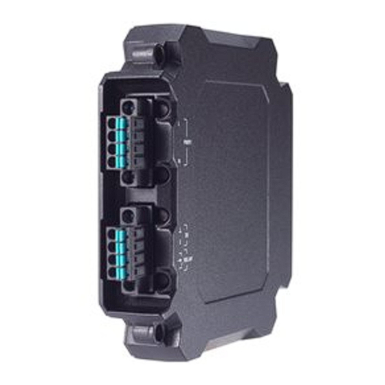
- Page 1 PWR-100 Power Module Series Quick Installation Guide Power Modules for EDS-4000/G4000 Series Version 1.0, July 2023 Technical Support Contact Information www.moxa.com/support 2023 Moxa Inc. All rights reserved. P/N: 1802001003010 *1802001003010*...
-
Page 2: Package Checklist
Package Checklist The PWR-100 Series power module is shipped with the following items. If any of these items are missing or damaged, please contact your customer service representative for assistance. • 1 PWR-100 Series power module • Quick installation guide (printed) •... -
Page 3: Wiring The Relay Contact
Please refer to the diagram below. Wiring the Relay Contact The PWR-100 Series power module has one set of relay outputs. This relay contact uses two contacts of the terminal block on the power module. Refer to the section for detailed instructions on how to connect the wires to the terminal block connector, and how to attach the terminal block connector to the terminal block receptor. -
Page 4: Wiring The Redundant Power Inputs
Wiring the Redundant Power Inputs The PWR-100 Series includes both high-voltage and low-voltage models. For the low-voltage (LV models) products, there are two power inputs for redundancy; for the high-voltage (HV models) products, there is only one power input. -
Page 5: Wiring The Digital Inputs
EDS devices’ right side. Wiring the Digital Inputs The PWR-100 Series power module has one set of digital inputs (DI). The DI consists of two contacts of the 4-pin terminal block connector on the EDS's right-side panel. Refer to the instructions and diagram below on how to connect the wires to the terminal block connector on the receptor. -
Page 6: Specifications
Specifications Power Note The EDS-4000/G4000 Series device model name and power parameters are determined by the installed PWR-100 power module. PWR-100–LV: -LV/-LV-T models PWR-105-HV-I: -HV/-HV-T models PWR-101-LV-BP-I: -LVA/-LVA-T models (PoE support) PWR-103-LV-VB-I: -LVB/-LVB-T models (PoE support) For example: EDS-G4008-T + PWR-100-LV = EDS-G4008-LV-T EDS-G4008-T + PWR-105-HV-I = EDS-G4008-HV- If you install a different power module, refer to the specifications of the corresponding model. - Page 7 PoE. If a PoE-capable PWR-100 Series module (PWR-101-LV-BP-I, PWR-103-LV-VB-I) is installed into an EDS-4000/G4000 Series non-PoE model, PoE functionality will not be available. Overload Current Present Protection at Input Reverse Polarity Present Protection Connection 2 removable 4-contact terminal blocks...
- Page 8 ATTENTION This device complies with Part 15 of the FCC rules. Operation is subject to the following conditions: 1. This device may not cause harmful interference. 2. This device must accept any interference received including interference that may cause undesired operation. - 8 -...


Need help?
Do you have a question about the PWR-100 Series and is the answer not in the manual?
Questions and answers