Table of Contents
Advertisement
Quick Links
Download this manual
See also:
User Manual
Advertisement
Table of Contents

Related Manuals for Moxa Technologies CA-132 series


Summary of Contents for Moxa Technologies CA-132 series
- Page 1 CA-132/132I Quick Installation Guide www.moxa.com/product Second Edition, November 2004 Moxa Technologies Co., Ltd. Tel: +886-2-8919-1230 Fax: +886-2-8919-1231 Web: www.moxa.com MOXA Technical Support Worldwide: support@moxa.com.tw The Americas: support@moxa.com...
- Page 2 The software described in this manual is furnished under a license agreement and may be used only in accordance with the terms of that agreement. Copyright Notice Copyright 2004 Moxa Technologies Co., Ltd. All rights reserved. Reproduction without permission is prohibited. Trademarks MOXA is a registered trademark of The Moxa Group.
-
Page 3: Table Of Contents
Table of Contents Chapter 1 Introduction………………………… 1-1 Overview............. 1-2 Package Checklist ..........1-2 Product Features ..........1-2 Product Specifications ........1-3 Chapter 2 Hardware Installation…………….. 2-1 Block Diagram of CA-132/132I ......2-2 RS-422/485 Interface Settings......2-3 I/O Base Address & Interrupt Vector Settings ..2-4 IRQ Setting ............ -
Page 5: Chapter 1 Introduction
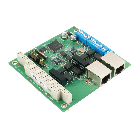
Introduction Chapter 1 Welcome to MOXA CA-132/132I Series of advanced 2-port RS-422/485 PC/104 communication modules, a new industrial multiport serial board solution. Both ports of CA-132/132I can be configured by DIP Switch for either the RS-422 or RS-485 interface, and with its PC/104 standard, the CA-132/132I Series is compatible with any PC/104 CPU module or CPU card that accepts PC/104 expansion modules. -
Page 6: Overview
Overview CA-132/132I is a PC/104 module that supports the RS-422/485 serial interfaces, and can be used with PC/104 CPU modules or CPU cards that accept PC/104 expansion modules. CA-132/132I has two independent serial interfaces, which are accessed through RJ45 connectors. You can configure both ports for the RS-422 or RS-485 interfaces by DIP switch. -
Page 7: Product Specifications
Introduction ! Switch selectable for I/O and INT Vector addresses (from Hex 000 to 3FF) ! 64-byte FIFOs ! IRQ settings are selectable by jumper ! Built-in 16 KV ESD surge protection for TX and RX lines ! 4 LED indicators onboard (red for TX, and green for RX) ! Support 4-wire RS-422 and 2/4-wire RS-485 ! ADDC™... -
Page 9: Chapter 2 Hardware Installation
Hardware Installation Chapter 2 This chapter includes information about hardware installation of CA-132/132I Series boards. The following topics are covered: Block Diagram of CA-132/132I RS-422/485 Interface Settings I/O Address & Interrupt Vector Settings IRQ Setting Initial Inspection RS-422/485 pin assignments... - Page 10 Block Diagram of CA-132/132I...
- Page 11 Hardware Installation RS-422/485 Interface Settings You can use DIP switches SW3 and SW4 to configure each port individually for either RS-422 (4-wire) or RS-485 (2/4-wire) interface with termination resistor on/off (120 ohm). SW3 configures Port 1, and SW4 configures Port 2, as shown in the switch setting diagrams below.
-
Page 12: I/O Base Address & Interrupt Vector Settings
I/O Base Address & Interrupt Vector Settings CA-132/132I Series boards have two 7-switch DIP switch panels, named SW1 and SW2. Panel SW1 is for I/O Base Address setting, and SW2 is for Interrupt Vector setting. Once you configure Port 1’s I/O Base Address and Interrupt Vector, the settings for the other ports will be configured automatically. - Page 13 Hardware Installation Example: When you wish to configure your Port 1’s I/O base address to 180, the DIP switch settings of panel SW1 should be as follows: 0 × 180 When you wish to configure your Port 1’s INT Vector to 1C0, the DIP switch settings of panel SW2 should be as follows: 0 ×...
- Page 14 At this point, the beginning of the I/O address for Port 2 will be configured automatically to 188. 0×000 0×200 0×300 0×380 0×3C0 0×3E0 0×3F0 0×3F8 0×008 0×018 0×038 0×078 0×0F8 0×2F8...
-
Page 15: Irq Setting
Hardware Installation IRQ Setting The IRQ settings of CA-132/132I Series are selectable by jumper. Before you insert a CA-132/132I board into the PC/104 interface, you need to choose an available jumper from 3, 4, 5, 6, 7, 9, 10, 11, 12, or 15 to configure the IRQ setting. - Page 16 SIGNAL DATA- DATA+...
Need help?
Do you have a question about the CA-132 series and is the answer not in the manual?
Questions and answers