Table of Contents
Advertisement
Quick Links
Advertisement
Table of Contents

Related Manuals for Contex HD Ultra X 6000 Series


Summary of Contents for Contex HD Ultra X 6000 Series
- Page 1 User Guide Wide Format Scanners Model: HD Ultra X 6000 Series UG13774-1D JUN 2018...
-
Page 2: Table Of Contents
Contents Network connection ................24 Table of Contents Turning Power ON/OFF ................25 About This Guide ..................3 Main power switch ................25 Main Specification ..................4 Scanner Self-Test ................. 25 Scanner ready to scan ................25 Packaging ....................5 Wake and Sleep modes ................ - Page 3 Contents Tips for using thick media ..............37 Regulations ................... 67 Modifying stitch for OTAC ..............37 FCC Regulations ................... 67 Toxic or Hazardous Substances or Elements ........67 Maintenance ....................38 Scanner dimensions ................68 About scanner maintenance ..............38 Low Adjustable Stand dimensions ............69 Overview of key maintenance points .............39 Scanner unpacked weight ..............
-
Page 4: About This Guide
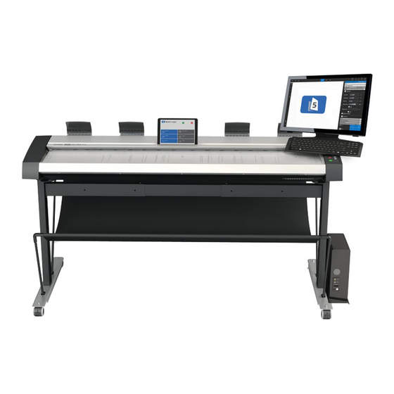
60” wide format color scanner HD Ultra X 6000 RB67G HD Ultra X 6000 Series scanner The guide assumes basic knowledge of your computer and operating system and does not repeat information covered in the documentation provided to support these technologies by their own manufacturers. -
Page 5: Main Specification
Power consumption : (Ready / Sleep Mode / Scanning) Max 39W / 1W / 130W (built-in power supply) Controlling software Contex Nextimage for Windows, iOS app and WIDEsystem 67kg (148 lbs) / 1810mm (71.2”) x 475mm (18.7”) x 200mm (7.9”) Unpacked weight / Dimensions (L x W x H) 76 kg (168 lbs) / 1950mm (76.7”) x 677 mm (26.7”) x 301mm (11.9”) -
Page 6: Packaging
Overview Packaging Packaging notes Be sure to retain the packing material if you intend to move the scanner to another site. Do not leave empty packaging where it can block a right of way or a fire exit. Always dispose of the packing material responsibly if it is no longer required. -
Page 7: Unpacking
Overview Unpacking WARNING: THIS SCANNER IS VERY HEAVY Assistance and safety Ensure you have adequate room available and suitable assistance on hand to help you unpack and position the scanner safely. BE CAREFUL. DO NOT TRAP YOUR FINGERS WHEN PLACING THE SCANNER ON THE FLOOR STAND! Lifting the scanner The scanner is very heavy and weighs 76 kg or 168 lbs. -
Page 8: Getting To Know Your Scanner
Overview Getting to know your scanner Scanner Front View Main parts required for scanner installation, operation and maintenance Release Lever for opening the scanner lid for maintenance Android / iPad Tablet Device (to clean the glass and / or remove obstructions) Paper Return Guides (optional and not included) Document Feed Tray... -
Page 9: Scanner Keypad / Operator Panel
Overview Scanner Keypad / Operator Panel Main parts required for scanner installation, operation and maintenance Scanner Error / Warning POWER ON / OFF RED (warming-up / self-test) GREEN (ready) Paper Loaded (Ready) Thick Media Activated Decrease Scan Speed Increase Scan Speed Paper Forward Button STOP / Abort Scan Paper Reverse Button... -
Page 10: Scanner Rear View
Overview Scanner Rear View: Main parts required for scanner installation, operation and maintenance Paper Return Guide (5) Paper Pressure Selector Portable Device (not included) Slot in scanner lid for portable device Ethernet USB3 socket Power cord and ON/OFF switch Keypad end Paper Return Thick media raise and Guide removed for clarity Power... -
Page 11: Installation
Installation Installation Follow the steps below to install the scanner drivers and WIDEsystem software. The installation of the Nextimage scanning software is not covered as part of this guide. Minimum system requirements Windows computer with Intel Core Duo, Core 2 Duo or i5 processors, 4GB RAM and 7200rpm HDD ... -
Page 12: Software
When successfully installed the WIDEsystem icon will show in the pc system tray. Remove the USB thumb drive Now install Contex Nextimage or scan and copy software from a third-party supplier : During all installation steps be sure to select ‘YES’ if Windows asks you to allow IMPORTANT the software to access the network. -
Page 13: Cleaning
Installation Cleaning Cleaning the scanner Clean the scanner feed tray The scanner feed tray is the external flat surface in front of the insertion slot. Lightly wipe this surface to remove any dirt and prevent it being transported by the document into the scan area where it might spoil the scan. - Page 14 Installation Cleaning the scanner Open the scanner lid by pushing it back The lid will begin to move upwards when the catches are released Open the lid fully backwards to expose the internal scan area Cleaning the scanner Clean the internal scan area Lightly wipe the glass plate area using a dry lint-free cloth.
-
Page 15: Connections
Installation Connections Connect power cable Connect the power cable to the scanner Connect the scanner mains power cable to the power socket on the back of the scanner. Connect power cable Connect the scanner to a power outlet Connect the power plug end of the scanner power cable to a power outlet. CAUTION: The scanner comes with a power cord that has a three-wire grounded plug. - Page 16 Installation Power ON the scanner Turn ON scanner power Turn on the main power switch at the back of the scanner. Connect Cables Connect the USB interface cable to the scanner Initial installation and activation of the scanner is easiest using the USB connection. 1.
-
Page 17: Widesystem Scanner Detection
Installation WIDEsystem scanner detection Connect USB cable to PC Connect the USB interface cable to the PC 1. On the scanner PC check that WIDEsystem is running by looking for the WIDEsystem icon in the system tray area of the PC screen (lower right). 2. -
Page 18: Energy Saving Settings
Installation Scanner installation Windows installs the scanner 1. Click ‘Next’ and follow the instructions on your screen to install the scanner on your PC. Most of the scanner installation process is automatic. Wait until the completion message appears Press ‘Next’ when done. IMPORTANT: During all installation steps, be sure to select “YES”... -
Page 19: Scanner Activation
Contact your dealer if you do not have a license key. Manual activation needs an Activation Code which can be obtained from your dealer or you can generate this yourself at the Contex Licensing website (see later in this section for more details) To start scanner activation: Press the Activate button to start the activation wizard then choose the Online if your PC is connected to the Internet. -
Page 20: Online Scanner Activation
Installation Online scanner activation Scanner Activation - Online Activating an online scanner (Online) Have your License Key ready. When you choose Online as the activation method, the wizard screen shown at the top right will appear. Enter you license key in the designated field The license key will be authenticated online and if valid, a green tick will appear as shown in the center screenshot Press the Activate button to continue... -
Page 21: Manual Scanner Activation
Installation Manual scanner activation Scanner Activation - Manual INTERNET DEVICE SCANNER Activating an offline scanner (Manual) License Key document from supplier You can still activate your scanner manually if it is not directly connected to the internet by using the Manual method. You will need a separate device or computer with an internet connection to enter two items of information. - Page 22 Installation Scanner Installation – Change network name Change the scanner network name (optional) NOTE: This step only appears with licensed Ethernet supported scanners as detected during activation. You may wish to change the default name of the scanner to comply with your organization.
-
Page 23: Scanner Calibration
Installation Scanner calibration Scanner Installation Calibrate the scanner (camera alignment) Always allow the wizard to re-calibrate the scanner after first receiving it to correct for any changes that might have occurred during its transportation. Press Calibrate to start the wizard Follow the wizard instructions to start camera alignment NOTE: If you did not clean the internal scan area and scanner glass in the previous installation steps please clean them now. - Page 24 Installation Scanner Installation Complete the installation The scanner has been installed correctly when you see this message.
-
Page 25: Network Connection
NOTE: Use only an approved gigabit cable. Full performance is not guaranteed with other cables or normal LAN cables. NOTE: WIDEsystem will detect and warn if the network is not gigabit. Contex recommend a gigabit network for best scanner performance. An internet connection is not required for scanning. -
Page 26: Turning Power On/Off
Switching ON and OFF Turning Power ON/OFF Main power switch Scanner Self-Test The main power switch is at the back of the scanner on the right side. When the scanner power is turned ON it runs a short self-test. Press the top side of the switch (marked “I”) to turn the main power ON. As part of this test, all of the LED lights on the keypad will light Press the lower side (marked “0”) to turn OFF the power. -
Page 27: Wake And Sleep Modes
Switching ON and OFF Wake and Sleep modes With the main power switch ON, scanner power can be forced into Sleep mode The scanner will go into Sleep mode: and taken back out into Wake mode. Sleep mode is an energy saving mode where the scanner cannot be operated. -
Page 28: Automatic Sleep
Switching ON and OFF Automatic Sleep By default, this is set for 15 minutes. NOTE: You will be prompted to change the idle time during installation. To set sleep mode options: Open WIDEsystem by double-clicking the WIDEsystem icon and select the Timer tab. Check the Enter Sleep mode automatically option. -
Page 29: Loading Originals Into The Scanner
Loading Loading Originals into the Scanner Center loading Load your document with the image side facing downwards into the funnel-shaped insertion area. Push the leading edge of the media into the funnel shaped slot so it contacts the rollers inside the funnel and hold it there. After a brief period, the scanner will detect the document and begin feeding it. At the same time, release your grip on the media. -
Page 30: Side Loading
Loading Side loading Scanning oversize documents For documents wider than the specified paper width of 62” the Right Paper Place the left adjustable paper guide on the left side of your document. As for center loading push the document into the funnel-shaped insertion slot Guide can be removed. -
Page 31: Automatic Loading
Loading Automatic loading Paper-return Guides Automatic loading takes the original as soon as it is inserted into the Paper-return guides force documents to the front after scanning for operator scanner funnel area. This setting is reliable for most scanning and convenience. -
Page 32: Unloading The Original
Loading Unloading the original Fast loading Fast loading is a batch scanning time saving option that stops the document Press the Paper Reverse button to at the first roller. It is selected from within the Nextimage scanning software return the original back to the scanner and can be used with automatic loading or manual loading. -
Page 33: Paper Pressure Adjustment
Loading Paper Pressure Adjustment Setting the input size Assist the movement of very thin documents through the scanner by The input size defines the scan area. This can be set in three different ways reducing the pressure the scanner exerts on the media. from the Nextimage scanning software. -
Page 34: Scanner Speed Control
Loading Scanner Speed Control Speed indication For fragile originals, it is advisable to slow down the scan speed. Pressing button A or button B will decrease or increase the scan speed and move the green led inside the speed indicator. It overrides the setting in the ... -
Page 35: Monitoring With Widesystem
Loading A greyed WIDEsystem icon indicates the scanner is off or in sleep mode. A Monitoring with WIDEsystem yellow icon shows it is connected. Mouse-over the icon for a quick WIDEsystem software monitors the scanner and reports on its functionality. statement of the current scanner status. -
Page 36: Optimized Thick Media Adjustment (Otac)
Thick media (OTAC) Optimized Thick Media Adjustment To scan thick media such as cardboard, foam board or Gator board the height of the insertion slot should be increased by activating the Optimized Thick Media Adjustment or OTAC for short. OTAC should be used when scanning documents from 2mm to 16mm thick Yellow led will light up when (0.6”). -
Page 37: Lowering Otac
Thick media Thick Media (OTAC) Lowering OTAC From the fully raised position (previous section), OTAC needs to be lowered down on to the thick media before scanning can be started. Yellow led light stays on when OTAC is in raised position Lowering OTAC for thick media (top lid button) ... -
Page 38: Tips For Using Thick Media
Thick media Tips for using thick media Modifying stitch for OTAC Originals that do not bend are imaged above the surface of the glass. This can cause image overlap (stitching) problems unless the operator adjusts ALWAYS return OTAC to the normal thin media position after using for it. -
Page 39: Maintenance
Maintenance Maintenance About scanner maintenance Regular scanner maintenance will keep the scanner working properly. There are three basic maintenance tasks: Cleaning the scanner How often you need to clean the scanner will depend on how much it is used and the condition of the media. Newspapers and old blueprints will make a scanner dirty much faster than new brochures and CAD plots. -
Page 40: Overview Of Key Maintenance Points
Maintenance Overview of key maintenance points The illustration below shows the scanner with its lid open. The illustration indicates the key points (parts and areas) you need to recognize when cleaning the scanner or changing parts. Instructions follow in the next sections. Release lever for opening the scanner lid for maintenance White background... -
Page 41: Cleaning The Scan Area
Maintenance Cleaning the scan area Caution: Always turn the scanner power off and disconnect the power Follow the steps below for thoroughly cleaning the scanner and scan area. plug before cleaning the scanner. Be sure to clean the scan area when results are not optimal. Even small dust particles in the scan area can cause streaks in your scanned image. - Page 42 Maintenance Cleaning the scan area Pull each lever upwards to release the scanner lid Open the lid with release levers Access the scan area by releasing the levers at each side of the scanner lid then lift the lid upwards. ...
- Page 43 Maintenance Cleaning the scan area Clean the scanner glass Clean the glass with a lint-free cloth and a mild, streak-free, glass cleaner. Apply the cleaner to cloth and wipe the glass-plate. Dry the glass completely using a separate clean, dry lint-free cloth like the one provided with the maintenance kit.
- Page 44 Maintenance Cleaning the scan area Lower rollers Clean the lower rollers The lower black rubber rollers are in two rows either side of the scan glass. Use a lint-free cloth and a mild, streak-free glass cleaner. Apply the cleaner to cloth and wipe the lower rollers in both rows. ...
- Page 45 Maintenance Cleaning the scan area Clean the scanner feed tray The scanner feed tray is the external flat surface in front of the insertion slot. Lightly wipe this surface to remove any dirt and prevent it being transported by the document into the scan area where it might spoil the scan.
-
Page 46: Camera Alignment And Calibration
Maintenance Camera Alignment and Calibration Scanner calibration is very easy to perform. Calibration is carried out using the WIDEsystem program you installed with your drivers. After manually cleaning the scan area, you just start the Calibration wizard and let it take over. The wizard will ask you to insert a calibration sheet. Other than that, scanner calibration is completely automatic. - Page 47 Maintenance Calibration Launch the calibration wizard On your PC – Double -click on the WIDEsystem icon in the system tray to open the WIDEsystem program. Press the Calibrate button. Calibration Select calibration type Select either Camera Alignment or Full Calibration. ...
- Page 48 Maintenance Calibration Insert the calibration sheet The wizard will now ask you to insert the Calibration Sheet that came with the scanner. The printed side must be inserted face up with its midpoint arrow lined up with the midpoint arrow on the lid of the scanner. Feed the sheet into the scanner.
-
Page 49: Replacing Scanner Parts
Maintenance Replacing Scanner Parts This section describes how to replace scanner parts that may wear down with prolonged use of the scanner (consumables). Replacing parts when needed is essential in order to retain optimal scanner image quality. WIDEsystem software monitors the scanner constantly and will announce when it is time to replace a component. -
Page 50: Replacing The Scanner Glass
Maintenance Replacing the scanner glass Replacing the scanner glass Turn the scanner power off and disconnect Turn off the power switch on the back of the scanner Disconnect the power plug Replacing the scanner glass Pull each lever upwards to release the scanner lid Open the lid with release levers Access the scan area by releasing the levers at each side of the scanner lid then lift the lid upwards. - Page 51 Maintenance Replacing the scanner glass Push the lid up and backwards The lid will begin to move upwards when the levers are released Open the lid all the way back to expose the internal scan area Replacing the scanner glass Locate the scanner glass ...
-
Page 52: Removing Scanner Glass
Maintenance Removing scanner glass Replacing the scanner glass Remove scanner glass Place an index finger under each end of the glass then starting at one end apply moderate upwards pressure to WARNING begin separating it from the scanner body ... - Page 53 Maintenance Replacing the scanner glass ATTENTION Remove scanner glass AFTER RELEASING GLASS ENDS, REPOSITION HANDS TO SUPPORT GLASS AT THE 1/3 AND 2/3 POINTS. Move your fingers to the 1/3 and 2/3 ALWAYS SUPPORT NEW GLASS IN THE SAME WAY. points BEFORE LIFTING the scanner glass away from the scanner.
-
Page 54: Inserting Scanner Glass
Maintenance Inserting scanner glass Replacing the scanner glass Insert new scanner glass Check that the flat magnetic surfaces inside the scanner are clean and free from dirt or dust. Use a small vacuum device if necessary. Carefully bring the new scanner glass near to the open scan area ... -
Page 55: Replacing The White Background
Maintenance Replacing the white background The white background can become worn and discolored after extended use and should be replaced. WIDEsystem software monitors the scanner constantly and will alert the operator when it is time for a replacement. Replacing the white background Turn scanner power off and disconnect the power ... - Page 56 Maintenance Replacing the white background Push the lid up and backwards The lid will begin to move upwards when the levers are released Open the lid fully backwards to expose the internal scan area Replacing the white background White background Locate the white background ...
- Page 57 Maintenance Replacing the white background Remove the white background Remove by levering at A to release lower White background edge then rotating whole part about B (colored red for identification) Use a flat-bladed screwdriver tip wrapped in a soft cloth or similar and gently push it into the gap between the metal and the white background at one ...
- Page 58 Maintenance Replacing the white background White background Install the new white background Insert by rotating whole part about A then (colored red for identification) pushing lower edge (dotted line) into the lid. Some levering with a soft tool may be ...
- Page 59 Maintenance Replacing the white background Prepare the scanner Close the scanner lid Recalibrating the scanner is recommended after changing the white background to ensure that no dirt or scratch information from the old white background remains in calibration memory for the new part.
-
Page 60: Downloading New Firmware
Firmware upgrades can be Installing new firmware downloaded from the Contex website or obtained from your dealer. The downloaded firmware .exe file must exist on the pc connected Upgrade your firmware: to the scanner. -
Page 61: Troubleshooting
Trouble Shooting Troubleshooting This section describes the most common issues that might occur with your scanner. Please look for a problem description that matches your situation and follow the recommendations before requesting a service call. Error reporting A yellow flashing led on the keypad or an error message box onscreen and a WIDEsystem Status tab error report means an error has occurred. -
Page 62: Solving Scanner Installation Issues
Trouble Shooting Solving Scanner Installation Issues Problem Possible Causes and Remedies The interface is not enabled on the PC or set up correctly. Check the interface has been installed correctly and the scanner is connected using the cable supplied in the box “Unknown device is found“... -
Page 63: Solving Common Scanning Issues
Trouble Shooting Solving Common Scanning Issues Problem Possible Causes and Remedies An error was detected Error Indicator LED blinking The error may be reported immediately through a message on your screen. If not, open WIDEsystem (scanner icon on your system tray) and select the Status tab to view additional information about the error. Perform one of the following: ... - Page 64 Trouble Shooting Problem Possible Causes and Remedies A paper jam condition will turn off the paper ready lamp and a paper jam report will appear in the WIDEsystem status tab. Error message: Paper Jam Remove the document from the scanner by pressing the paper reverse or paper forward button on the keypad ...
- Page 65 Trouble Shooting Problem Possible Causes and Remedies This is often caused by dirt or scratches on the white background or dirt or glue on the scan glass. Clean both of these surfaces then reboot the scanner by turning it on and off. Now carry out an alignment and calibration maintenance procedure Error message: Correction of Camera X as described earlier in this guide failed...
-
Page 66: Solving Common Image Issues
Trouble Shooting Solving Common Image Issues Problem Possible Causes and Remedies Check in Nextimage that the input size is set for auto detection or set for a paper size large enough to cover the whole of the original Incomplete image or copy ... -
Page 67: Appendix
Appendix Appendix Important Safety Instructions H. Slots or openings in the cabinet at the back or bottom are provided for Read all of these instructions and save them for later use. Follow all ventilation. This ensures reliable operation of the product and protects it warnings and instructions marked on the scanner. -
Page 68: Regulations
Appendix Regulations Toxic or Hazardous Substances or Elements 有毒有害物质或元素名称及含量 FCC Regulations Part Toxic or hazardous Substances and Elements 有毒有害物质或元素 NOTE: This equipment has been tested and found to comply with the limits Name Lead Mercury Cadmium Hexavalent Polybrominated Polybrominated for a Class A digital device, pursuant to Part 15 of the FCC Rules. These 部件名称... -
Page 69: Scanner Dimensions
Appendix Scanner dimensions Height mm (inches) Length mm (inches) Scanner Feed tray height (H) and scanner length (L) 96.6 (38) 99.1 (39) 1016 (40) 1810 (71.2) NOTE: The stand is adjustable for three different heights. See instructions included with stand for more details. The low adjustable stand accessory is not standard equipment for the HD Ultra X 6000 scanner and must be ordered separately. -
Page 70: Low Adjustable Stand Dimensions
Appendix Low Adjustable Stand dimensions Height mm (inches) Length mm (inches) Low Adjustable Stand Height (H) and length (L) 766 (30.1) 791 (31.1) 816 (32.1) 1796 (70.7) NOTE: The stand is adjustable for three different heights. See instructions included with stand for more details. The low adjustable stand accessory is not standard equipment for the HD Ultra X 6000 scanner and must be ordered separately. -
Page 71: Scanner Unpacked Weight
Appendix Scanner unpacked weight Scanner Weight kg (lbs) HD Ultra X 6000 67 (148)
Need help?
Do you have a question about the HD Ultra X 6000 Series and is the answer not in the manual?
Questions and answers