
Related Manuals for Dräger Evita 4


Summary of Contents for Dräger Evita 4
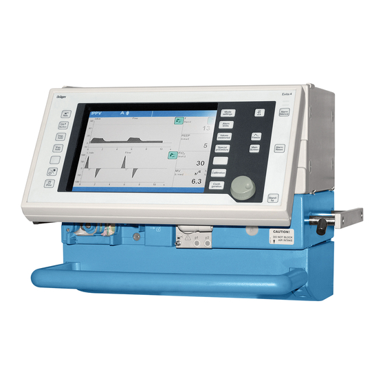
- Page 1 M E D I C A L Evita 4 Intensive Care Ventilator Instructions for Use Software 4.n...
- Page 2 – if the check values are not met on checking calibration with filter or calibration gas. – as part of the half-yearly inspection of Evita 4. Page body... the Instructions for Use Switch on Evita 4. Wait about for 3 minutes for in combined text/illustrations.
-
Page 3: For Bipap And Simv, For Weaning Without Transitions
– can be selected as starting configuration External flow source available as software version 4.n plus upgrade – The amount of external flow is calculated by Evita 4.4n Extended range of settings for the alarm time (e.g. for additional tracheal gas insufflation) and >... -
Page 5: Table Of Contents
Contents Contents For Your Safety and that of Your Patients ..........11 Intended Medical Application..............13 Operating Concept...................15 Structure of the Control Unit..............16 On-Screen Controls................. 17 Screen Keys for Function Selection without Confirmation..................18 Screen keys for Function Selection, Adjustment and Confirmation..............18 On-Screen Parameter Setting Knobs............20 Screen Pages...................21 Standard page...................22... - Page 6 Contents Contents If using bacterial filters................35 Supply and Connections................36 Electrical power supply................36 Note on use of a socket strip for ancillary equipment........36 Temporary interruption of power supply............. 36 Gas supply....................37 Evita Remote (optional)................38 Connection....................38 Note automatic self-test................39 Nurse call (optional)..................40 Technical Data...................40 Before Using for the First Time...............
- Page 7 Contents Contents Apnoea ventilation................... 76 Setting Alarm Limits.................77 In the Event of an Alarm................78 Cancel alarm tone..................79 Information .................... 79 Displaying Curves and Measured Values..........80 Displaying measured values...............81 Trends.......................82 Loops......................83 Reference curve displays................83 Single stroke displays................83 Zoom loops (optional)................83 Display loops in the upper graphic area.............
- Page 8 Contents Contents Screen....................109 Selecting displayed measured values............109 Selecting displayed curves..............111 Selecting displayed trends...............112 Ventilation....................113 Selecting ventilation modes..............113 Selecting Pmax pressure limit..............115 ® Selecting AutoFlow as start-up ventilation mode........116 Apnoea ventilation On/Off............... 117 Selecting patient mode................118 Start-up values for ventilation parameters and alarm limits......
- Page 9 Contents Contents What's what................... 147 Control unit..................... 148 Front connections................... 149 Back panel....................150 Technical Data..................151 Environmental conditions................. 152 Settings....................152 Performance data..................153 Measured value displays................153 Monitoring....................155 Operating data..................156 Machine outputs..................157 Electromagnetic compatibility (EMC)............158 Classification...................158 UMDNS-Code..................158 Materials used..................158 Description.....................159 Ventilation Modes..................
- Page 10 Contents Contents Abbreviations..................178 Symbols....................181 Bibliography................... 182 Parts List....................183 Order List....................185 What was new in Evita 4 software 2.n........... 187 What was new in Evita 4 software 3.n........... 188 Index...................... 189...
-
Page 11: For Your Safety And That Of Your Patients
For Your Safety and that of Your Patients For Your Safety and that of Your Patients Strictly follow the Instructions for Use Liability for proper function or damage Any use of the apparatus requires full understanding and The liability for the proper function of the apparatus is strict observation of these instructions. - Page 12 If a fault is detected in Evita 4 so that its life-support occur. functions are no longer assured, ventilation using an independent ventilation device must be started without This equipment must not be used with flammable delay –...
-
Page 13: Intended Medical Application
Intended Medical Application Contents Intended Medical Application Contents Intended Medical Application..............14... - Page 14 – IRV (Inversed Ratio Ventilation) If apnoea occurs, Evita 4 emits an alarm after the preset alarm period (T > ) and starts volume-controlled Apnoea SIMV Synchronized Intermittent Mandatory Ventilation, ventilation.
-
Page 15: Operating Concept
Operating Concept Contents Operating Concept Contents Structure of the Control Unit..............16 On-Screen Controls................17 Screen Keys for Function Selection without Confirmation................18 Screen keys for Function Selection, Adjustment and Confirmation..............18 On-Screen Parameter Setting Knobs............20 Screen Pages..................21 Standard page..................22 »Adjustment«... -
Page 16: Structure Of The Control Unit
Structure of the Control Unit The main components of the control unit are the screen, a set of fixed function keys and the central rotary dial- Evita 4 knob. The function keys are used to call up the screen pages appropriate to the application. -
Page 17: On-Screen Controls
Operating Concept Structure of the Control Unit On-Screen Controls The power switch for switching the device on/off. The power switch is located on the back panel and has a pivoting cover to protect against being inadvertently switched off. On-Screen Controls The lower half of the screen contains touch-sensitive IPPV Assist... -
Page 18: Without Confirmation
Operating Concept On-Screen Controls Screen Keys for Selecting Functions without Confirmation e.g. for paging through the system on-screen IPPV Assist for changing the menu [mbar] for switching over displays 33 > peak plat 5.3 _ t [s] 11:06 total 1.5 11:06 total 1.5 Zoom in Table... - Page 19 Operating Concept On-Screen Controls 1 Touch the relevant screen key for the alarm limits, e.g.: 2.3 L/min 2.3 L/min The colour changes from green to yellow = setting function is set. 2 Turn the rotary knob = adjust the alarm limit. The value is displayed in the screen key.
- Page 20 Operating Concept On-Screen Controls Screen Knobs for Setting Parameters Display (example): IPPV Assist [mbar] 33 > peak plat 5.3 _ t [s] Basic IPPV settings .500 Extra BIPAP settings insp SIMV Flow PEEP e.g. »PEEP« screen knob. 1 Touch the »PEEP« screen knob: It changes colour from green to yellow = setting function selected.
-
Page 21: Screen Pages
Measured values are displayed in the upper right- hand quarter of the screen. Help functions appear in the bottom line of the screen. On the right, Evita 4 provides setting instructions. On the left, Evita 4 provides information on the current status – this information can be accessed by pressing key »... -
Page 22: Standard Page
Operating Concept Screen Pages Screen page For displaying the ventilation status Press » « key. Display (example): The standard page shows the ventilation situation at a glance – reduced to the most important measurement parameters and curves. Four measured values are shown on the right, and two curves on the left. - Page 23 For detailed instructions on setting the ventilation modes, please refer to page 49. Cancel selection/setting Press the screen key or screen knob again. Evita 4 Press another screen key or another screen knob. To quit a screen page: 1 Press »...
-
Page 24: Alarm Limits« Screen Page
Operating Concept Screen Pages »Alarm limits« Screen Page This page is used for: Displaying the measured values and the corresponding alarm limits. Setting the alarm limits. Setting the monitoring function. Displaying the logbook. The alarm limits are grouped together in a field and combined with a curve and four measured values. -
Page 25: Measured Values« Screen Page
Operating Concept Screen Pages »Measured values« Screen Page This page is used to display: – the measured values in table format – the trend curve – loops – logbook. Tables, trend, loop and logbook are selected by the right- hand block of screen keys. Example table of measured values »Table 1«... -
Page 26: Measurement Manoeuvre« Screen Page
« screen keys. Calibration starts as soon as the relevant key is pressed. Evita 4 provides the necessary calibration instructions in the Help Function line at the bottom of the screen. For detailed operating instructions, please refer to page 97 et seq.. -
Page 27: Configuration« Screen Page
For detailed operating instructions, see page 107. Control Unit Location To adapt to the situation of the ventilation location, the control unit can be placed Evita 4 either directly on the device separately, on a wall rail. For detailed instructions on placing, see page 47. -
Page 29: Preparation
Preparation Contents Preparation Contents Attaching components................30 Fitting expiration valve................30 Fitting flow sensor..................30 Fitting O sensor capsule................. 31 Note on Use of Heat and Moisture Exchanger (HME)......31 Ventilation Adults and Children.............. 32 Connecting Aquapor humidifier..............32 Connecting ventilation hoses..............32 Fitting temperature sensor................ -
Page 30: Attaching Components
Preparation Attaching components The following instructions include: – Equipment assembly. – Electrical and gas connections. – Setting the language for the display texts. – Automatic device check with sensor calibration. Attaching components Always use properly prepared parts, see Preparing, page 135. Fitting the expiration valve Tilt the control unit upwards. -
Page 31: Fitting O 2 Sensor Capsule
Preparation Attaching components Heat and Moisture Exchangers Fitting O sensor capsule – when using the system for the first time – when the display reads: measurement inop – when calibration can no longer be performed. Tilt control unit upwards. 1 Turn port downwards or to the left. 2 Use coin to loosen screw, and remove protective cover. -
Page 32: Ventilation Adults And Children
Fill Aquapor bowl to the upper mark with distilled water. Connecting ventilation hoses Do not use antistatic or conductive hoses*. Evita 4 Depending on the desired position of the ventilator in relation to the bed, the hinged arm can be fitted to either side of the machine. -
Page 33: Fitting Temperature Sensor
Preparation Ventilation Adults and Children 1 Hang the hinged arm from the rail on the left-hand side and tighten screws. Connect ventilation hoses, and note length of hose (metres). 2 Turn ports in direction of hoses. 3 Install water traps in vertical position. Connect the Y-piece, with the rubber sleeve of the Y-piece on the inspiratory side. -
Page 34: Fitting Co 2 Cuvette And Co 2 Sensor
Insert the probe of the CO sensor in the socket »CO « on the rear panel of the Evita 4. Ventilating Infants Up to 300 mL tidal volume V Patient mode »Paediatrics« Do not use a heat and moisture exchanger at the... -
Page 35: Fitting Humidifier And Ventilation Hose
0,6m Fit the water trap in the vertical position. 0,6m Do not place any liquid containers above or on top of Evita 4! Any leaking or spilled liquid could cause malfunctions! If using bacterial filters The use of expiratory bacterial filters on the ventilator is not recommended. -
Page 36: Supply And Connections
During a power interruption, Evita 4 outputs a continuous alarm tone for max. 2 minutes. The duration of this alarm tone may be shorter if Evita 4 was switched on for less than 15 minutes. Evita 4 tolerates power interruptions shorter than 10 milli- seconds –... -
Page 37: Gas Supply
Supply and Connections Gas supply Screw the connecting hoses for medical air and oxygen to the back panel of Evita 4 and insert their probes into the terminal units. The compressed gases must be dry and free from dust and oil. Gas pressure must be 3 to 6 bar. -
Page 38: Evita Remote (Optional)
Evita 4 and is described in the application chapters of the Instructions for Use. Connection Plug the lead of the Remote Pad into the socket » « on the rear of Evita 4. The plug can be connected or disconnected at any time without impairing operation of Evita 4. -
Page 39: Note Automatic Self-Test
Hook holder onto a standard rail and clamp into place. Hang Remote Pad into holder from above. Note automatic self-test – when connecting the Remote Pad to Evita 4 while the latter is switched on – when switching on Evita 4 after connecting the Remote Pad. -
Page 40: Nurse Call (Optional)
Nurse call (optional) Nurse call (optional) Socket on the rear of Evita 4 for connecting alarm signals to a central alarm station in the hospital. The kit may only be installed by specialists. The 6-pin round DIN plug (female connector) must be connected to the lead for the central alarm station in the hospital by a specialist. -
Page 41: Before Using For The First Time
Evita 4 runs through its self-test procedure, Wait until the 10-second test phase is complete. After the self-test: 1 Switch Evita 4 to Standby = hold down key » « for about 3 seconds. 2 Switch off the standby alarm tone with the »Alarm Reset«... -
Page 42: Device Check
Immediately before using on the patient, check that the machine is working properly and is ready for operation. Evita 4 supports this »device check« by means of a built- in checklist that guides the user through the test in a dialogue mode. -
Page 43: Performing Device Check
Only insert the elbow connector into the Y-piece when Evita 4 advises you to do so on the screen. Performing the device check Switch on the machine = press power switch on the back panel until it clicks into position. - Page 44 Before starting the check, enter the type of humidifier selected: – Active humidifier, e.g. Dräger Aquapor – HME/Filter (artificial nose) If the type of humidifier is known, Evita 4 can take the temperature and moisture situation into account when measuring the volume parameters. Touch the »Humid.« screen key.
- Page 45 After successful completion of the device check, Evita 4 Evita 4 is ready for operation. Either: immediately start up Evita 4 by pressing key » « leave Evita in standby mode switch off Evita for later use. Switch on back panel = pivot flap to the side and...
-
Page 46: Checking The Hose System For Leaks
A leakage flow of 300 mL/min at a pressure of 60 mbar is permitted. After the leak test, the Evita 4 unit determines the compliance and resistance of the hose system. The calculated compliance of the hose system is used by... -
Page 47: Positioning The Control Unit
Release the control unit = turn the latch away from the wall rail and lift the control unit off the rail. Coil the cable. Hang the control unit in the Evita 4 mounting so that it rests in position. Hold down the segments on the right and left, and at the same time tilt the control unit to the optimal position. -
Page 49: Operation
Operation Contents Operation Contents Starting up..............50 Selecting/Quitting Standby Mode......96 Switching on..............50 Calibration..............97 Patient mode............50 Calibrating O sensor..........97 Selecting the patient mode.........51 Calibrating flow sensor..........98 Entering the ideal body weight........51 External flow source...........99 Select the previous settings........51 Checking/calibrating CO sensor...... -
Page 50: Starting Up
After power cuts and after standby mode, the settings valid immediately before the interruption of operation remain in use. Patient mode After switching on, Evita 4 displays a choice of patient modes: – »Adults« = adult patients – »Paed.« = children –... -
Page 51: Selecting The Patient Mode
(e.g. NeoFlow), thus preventing restoration of the previous setting. Restoration of the previous setting is similarly prevented by Evita 4 if it was configured in such a way before switching off that the former patient mode is no longer available. -
Page 52: Starting Ventilation
Operation Starting up Starting ventilation Press the rotary knob again. Evita 4 starts ventilation with the ventilation mode configured by the user. The machine is factory-set to IPPV. Evita 4 displays the »Settings« screen page. The user can check and correct the settings on the... -
Page 53: Setting Ventilation Modes
Operation Setting Ventilation Modes Setting Ventilation Modes The ventilation modes IPPV, BIPAP, SIMV and ASB are already configured in the unit. If other ventilation modes are used, please refer to page 113 "Selecting ventilation modes". IPPV Intermittent Positive Pressure Ventilation Volume-controlled ventilation with fixed, mandatory Insp. - Page 54 Evita 4 delivers additional inspiration flow if and when the patient breathes in – limited by the alarm limit V > The patient can also breathe out during the inspiratory plateau phase.
- Page 55 Operation Setting Ventilation Modes –––––––––––––––––––––––––––––––––––––––––––––––– To set: Touch the »Extra settings« screen key. Touch the screen key corresponding to the desired function. For Flow Trigger and Sigh: Touch the appropriate screen key. Adjust the desired value = turn the rotary knob Confirm the desired setting = press the rotary knob Switch on the function = touch the »On«...
-
Page 57: Simv, Simv/Asb
Operation Setting Ventilation Modes SIMV, SIMV/ASB Synchronized Intermittent Mandatory Ventilation* Assisted Spontaneous Breathing** Fixed mandatory minute volume MV set with tidal volume ASB pressure and frequency f. Between the mandatory ventilation assist Pmax strokes, the patient can breathe spontaneously, thereby (configurable) fast slow... - Page 58 ASB pressure support ventilation stops breathing. rapid slow If breathing stops, Evita 4 emits an alarm after the set rise time rise time PEEP alarm time (T > ) and starts volume-controlled Apnoea ventilation with the set ventilation parameters: Frequency »f...
- Page 59 Operation Setting Ventilation Modes Pressure Limited Ventilation (PLV)* – for manually limiting pressure peaks using the Pmax pressure limit. The tidal volume remains constant as long as the pressure curve shows a plateau and the inspiratory flow curve shows a brief flow pause between inspiration and expiration.
-
Page 60: Bipap, Bipap/Asb
Operation Setting Ventilation Modes BIPAP, BIPAP/ASB Biphasic Intermittent Positive Airway Pressure Assisted Spontaneous Breathing Pressure-controlled ventilation combined with free spontaneous breathing during the complete breathing fast slow pressure assist rise time rise time cycle, and adjustable pressure support at CPAP level. fast slow The mandatory proportion of the total minute volume MV... - Page 61 Apnoea Ventilation – for automatic switch-over to volume-controlled mandatory ventilation if the patient stops breathing. If breathing stops, Evita 4 emits an alarm after the set alarm time (T > ) and starts volume-controlled Apnoea ventilation with the set ventilation parameters: Frequency »f...
-
Page 62: Bipap Assist
Operation Setting Ventilation Modes BIPAP Assist Biphasic Positive Airway Pressure Assisted fast slow pressure-controlled, assisted ventilation rise time rise time The inspiratory strokes are the same as for BIPAP, but Pinsp the changeover from Pinsp to PEEP is not synchronised PEEP with expiration by the patient. -
Page 63: Cpap, Cpap/Asb
Apnoea Ventilation – for automatic switch-over to volume-controlled mandatory ventilation if the patient stops breathing. If breathing stops, Evita 4 emits an alarm after the set alarm time (T > ) and starts volume-controlled Apnoea ventilation with the set ventilation parameters. - Page 64 Operation Setting Ventilation Modes –––––––––––––––––––––––––––––––––––––––––––––––– To set (Example: Flowtrigger) Touch the »Extra settings« screen key. Touch the »Flow trigger« screen key. Set the value = touch the »FlowTrig« screen knob, and turn and press the rotary knob. ––––––––––––––––––––––––––––––––––––––––––––––––...
-
Page 65: Mmv, Mmv/Asb
Operation Setting Ventilation Modes MMV, MMV/ASB Mandatory Minute Volume Ventilation Assisted Spontaneous Breathing The overall minute volume is preset to a mandatory level, which can be adjusted by means of the tidal volume V and frequency f. The patient can breathe spontaneously, thereby contributing a portion of the overall minute volume. - Page 66 Evita 4 delivers additional inspiration flow when the patient breathes in – limited by the alarm limit V > The patient can also breathe out during the inspiratory plateau phase.
-
Page 67: Aprv
Apnoea Ventilation – for automatic switch-over to volume-controlled mandatory ventilation if the patient stops breathing. If breathing stops, Evita 4 emits an alarm after the set alarm time (T > ) and starts volume-controlled Apnoea ventilation with the set ventilation parameters: Frequency »f... - Page 68 Operation Setting Ventilation Modes –––––––––––––––––––––––––––––––––––––––––––––––– To set (Example: Apnoea Ventilation) Touch the »Extra settings« screen key. Touch the »Apnoea vent.« screen key. Switch on the function = touch the »On« screen knob and press in the rotary knob. Set values = touch the corresponding screen knob, turn and press rotary knob.
-
Page 69: Independent Lung Ventilation Ilv
– Evita 2 or Evita units must be fitted with the EvitaBus analogue interface (optional). – Connecting cable 84 11 794 must be used to connect Evita 4 to another Evita 4 or with an Evita 2 dura. – Connecting cable 84 11 794 must be used to connect Evita 4 to an Evita 2 or Evita. - Page 70 Operation Independent Lung Ventilation ILV For Evita 4 – Evita 2 Evita 4 – Evita: Connect the ILV port of the Evita 4 to the analogue interface of the other Evita unit using connecting cable 84 11 793.
-
Page 71: Setting The Master And Slave Device
Operation Independent Lung Ventilation ILV Setting the Master and Slave device To perform independent lung ventilation: Set up one device for ILV/Master mode the other device for ILV/Slave mode. Set the desired parameters – see page 19. Do not activate ILV mode until all the parameters for the ILV/Master and ILV/Slave are fully set. - Page 72 Operation Independent Lung Ventilation ILV Sigh – for prophylactic treatment of atelectasis. Atelectasis can be prevented by switching on the Sigh function and setting the sigh in the form of an intermittent PEEP. When the Sigh function is activated, the end-expiratory pressure is increased by the set value of the intermittent PEEP for 2 ventilation strokes every 3 minutes.
- Page 73 Operation Independent Lung Ventilation ILV Setting ILV/Slave Insp. Volume-controlled ventilation with fixed, mandatory pause minute volume MV, set with the tidal volume V frequency f of the ILV Master device and selectable Slave Pmax Pplat (configu- mode. PEEP rable) For independent lung ventilation of patients with no spontaneous breathing.
- Page 74 Operation Independent Lung Ventilation ILV ILV: Master and Slave Synchronisation Master Master device I:E ratio insp Slave device Slave Sync. Sync. – The I:E ratio of the slave device is determined by the I:E ratio of the master device. The start of inspiration is synchronised with the inspiration of the master device.
- Page 75 Operation Independent Lung Ventilation ILV Set the ventilation pattern for ILV/Slave with the following ventilation parameters: Tidal volume »V T« Insp. flow »Flow« Frequency »f« Inspiration time »T « insp concentration »O « Positive end-expiratory pressure »PEEP« –––––––––––––––––––––––––––––––––––––––––––––––– To set: Touch the appropriate screen knob.
-
Page 76: Apnoea Ventilation
ASB pressure support PEEP It can be switched on in the ventilation modes SIMV, BIPAP, CPAP, APRV. Evita 4 emits an apnoea alarm if during the set alarm period »T « no expiration flow is measured or Apnoea insufficient inspiratory gas is delivered. -
Page 77: Setting Alarm Limits
Operation Setting Alarm Limits Setting Alarm Limits Press key »Limits«. Display screen »Alarm limits« (example): This page displays all the adjustable alarm limits. < = lower alarm limit > = upper alarm limit Example: Lower alarm limit for minute volume MV. Touch the screen key for MV: the key changes colour from green to yellow. -
Page 78: In The Event Of An Alarm
Example: Apnoea Warning messages are displayed against a red background. Evita 4 generates a 5-tone sequence that is sounded twice and is repeated every 7 seconds. Caution = medium priority message The yellow lamp flashes. Warning messages are marked with two exclamation marks. -
Page 79: Cancel Alarm Tone
1 Press »Alarm Reset« key. The message is erased from the screen. However, it is stored in Evita 4 and can be displayed with the logbook function in the »Measured Values« screen page, see page 85. -
Page 80: Displaying Curves And Measured Values
Operation Displaying Curves and Measured Values Displaying Curves and Measured Values In the standard page Press » « key. »Standard page« display: In the right-hand field: 4 measured values In the left-hand field: 2 curves To select one of the three measured value combinations: Touch screen key »... -
Page 81: Displaying Measured Values
Displaying measured values Press the »Meas. values« key. »Table 1« display Evita 4 displays the measured values with the units of measure in the form of a table. The measured values are summarised in Table 1 and Table 2. »Table 2« display The following are displayed optionally: –... -
Page 82: Trends
Operation Displaying Curves and Measured Values Trends Touch the »Trends« screen key. »Trend« display: The trend of two measured values is displayed. To enlarge the time window (zoom function): Touch the »Zoom out« screen key. To reduce the time window: Touch the »Zoom in«... -
Page 83: Loops
Operation Displaying Curves and Measured Values Loops Touch the »Loops« screen key. »Loop« display: Two pairs of measured values plotted against each other appear in the ventilation cycle as a loop, e.g. the Paw-V loop and the V-Flow loop. To select another preset pair of measured values as a loop: Touch the »... -
Page 84: Display Loops In The Upper Graphic Area
Operation Displaying Curves and Measured Values Return to the normal loop display: Touch the »Zoom« screen key. The time-based curve automatically reappears when the loop page is exited. Display loops in the upper graphic area (available as upgrade) Touch the » «... -
Page 85: Logbook
Turn the rotary knob counter-clockwise, and position the box cursor over the desired line. Evita 4 enters all alarms in the logbook. If an alarm is not displayed on the screen immediately when it occurs, for instance because the device has signalled an alarm with higher priority, the undisplayed alarm is correspondingly highlighted with an asterisk (*) in the logbook. -
Page 86: Screen Freeze
Operation Displaying Curves and Measured Values Screen freeze Evita 4 To "freeze" the curves and loops (freezing loops is optional) 1 Press »Stop« key. To display the pair of measured values, a point on the curve or loop: 2 Position the cursor on the relevant point by turning the rotary knob. -
Page 87: Special Functions
2 Hold down the »Exp. hold« key. The expiration phase remains effective as long as the key is held down and Evita 4 determines the measured NIF value. If the key is not released, the device automatically terminates the expiration phase after 15 seconds. -
Page 88: Medicament Nebulisation
Medicament nebulisation Medicament nebulisation During adult ventilation Applicable in every ventilation mode. Evita 4 applies the medicament aerosol in synchronisa- tion with the inspiratory flow phase and maintains the minute volume constant. The medicament nebuliser is supplied by the ventilator... - Page 89 Operation Special Functions Medicament nebulisation The medicament nebuliser is automatically switched off after 30 minutes. After administration of the aerosol, the flow sensor is automatically cleaned and calibrated in order to prevent malfunctions in flow measurement. Only use medicament nebuliser 84 12 935 (white central body).
- Page 90 Medicament nebulisation 1 Connect the nebuliser hose to the port on the front Evita 4 panel of the Evita 4. Fill the medicament nebuliser in accordance with the specific Instructions for Use. Warning: the effect of aerosols on sensors, filters and heat and moisture exchangers (HME) must be taken into account.
-
Page 91: Oxygen Enrichment For Bronchial Suction
180 s The remaining time is counted down continuously. This initial oxygen enrichment lasts for a maximum of 180 seconds. During this time, Evita 4 waits for a dis- connection for suction. If there is no disconnection after expiry of the 180 seconds, the oxygen enrichment program is terminated. - Page 92 Special Functions Oxygen enrichment for bronchial suction After disconnection for suction Evita 4 delivers a minimal flow for the duration of suction in order to detect automatically the end of the disconnection phase. In the help line at the bottom edge...
-
Page 93: Special Measurement Procedure: Intrinsic Peep
Operation Special Functions Special measuring procedure: Intrinsic PEEP Intrinsic PEEP* is the actual end-expiratory pressure in the lung. Due to the dynamics of lung mechanics (resistance, compliance and closing volume) and the ventilation setting parameters, the intrinsic PEEP differs from the PEEP in the upper airways. -
Page 94: Special Measurement Procedure: Occlusion Pressure P 0.1
To evaluate the measured value at a particular time: Position the l cursor on the time by turning the dial- knob. The relevant measured value is displayed above the curve. Evita 4 displays the P 0.1 value as a negative pressure without the minus sign. -
Page 95: Shut-Down
Operation Special Functions Switching off the monitor functions e.g. if a spent sensor cannot be replaced. Immediately make sure there is an adequate external monitor backup! Example: Switching off Flow Monitoring. Press »Alarm limits« key. Display (example): Touch »Monitoring« screen key. Display (example): For the example of switching off flow monitoring: Touch the »Flow off«... -
Page 96: Selecting Standby Mode
No ventilation takes place in standby mode! Evita 4 Uses of Standby: – to perform the device check – to maintain Evita 4 ready for operation while the patient is absent. – to change patient mode. 1 Hold down the »... -
Page 97: Calibration
Operation Calibrating Calibrating The last calibration/zeroing values remain stored until the next calibration/zero calibration, even when the machine is switched off. Calibration of the pressure sensors for measuring the airway pressure is automatic. There is an automatic calibration of flow and O sensor daily. -
Page 98: Calibrating Flow Sensor
Touch the »Start Cal.« screen key. The LED in the screen key turns yellow. Display: Evita 4 uses the next inspiration phase for the calibration. Short inspiration times are prolonged to about 1 second. Message in the help line at the bottom of the screen:... -
Page 99: External Flow Source
The following prompt is also displayed on Evita 4: Confirm value with Confirm = press rotary knob. Calculation of the external flow is interrupted by Evita 4 if it is greater than 12 L/min or the flow measurement function is defective. -
Page 100: Checking/Calibrating Co 2 Sensor
– before each calibration test, page 102 onwards – before each CO calibration, page 105. Switch on Evita 4. Wait about 3 minutes for completion of the warm-up phase of the CO sensor. After about 3 minutes, the measured values will be within the specified accuracy. - Page 101 1 Remove CO sensor from the cuvette, 2 place the sensor on its park bracket, confirm with dial-knob: zero calibration will now be performed. Evita 4 Display: zero calibration After about 5 seconds, the device confirms with the message: zero ok Fit the sensor back on the cuvette.
-
Page 102: Testing Co 2 Calibration With Test Filter
Checking CO calibration with test filter Use the test filter on the cable of the CO sensor. Switch on Evita 4, and wait for about 3 minutes for the CO sensor to complete its warm-up phase. Press the »Calibration« key. -
Page 103: Testing Co 2 Calibration With Test Gas
– if the specified calibration value was not met when testing with the test filter – at least once per half-year. Switch on Evita 4. Wait about 3 minutes for the CO sensor to complete its warm-up phase. Press the »Calibration« key. - Page 104 Operation Calibrating Display (example): Carry out CO zero calibration, see page 100. After completing CO zero calibration: Touch the »Gas Check« screen key. Connect the calibration gas supply. Use the cuvette from the calibration set! 1 Connect the calibration gas cylinder and cuvette of the calibration set to the hose.
-
Page 105: Calibrating Co Sensor
– if the check values are not met on checking calibration with filter or calibration gas. – as part of the half-yearly inspection of Evita 4. Switch on Evita 4. Wait about for 3 minutes for the machine to complete its warm-up phase. Press the »Calibration« key. -
Page 106: Resetting Co 2 Calibration
Touch the »Start« screen key. During calibration, the following message is displayed on the screen: calibration. Please wait Evita 4 carries out calibration and confirms with the message: calibration ok Failed calibration is indicated by the device with the message:... -
Page 107: Configuration
Configuration Contents Configuration Contents Sound....................108 Adjusting the volume of the alarm tone............108 Screen....................109 Selecting displayed measured values............. 109 Selecting displayed curves..............111 Selecting displayed trends..............112 Ventilation..................... 113 Selecting ventilation modes..............113 Selecting Pmax pressure limit..............115 ® Selecting AutoFlow as start-up ventilation mode........116 Apnoea ventilation On/Off.............. -
Page 108: Sound
Configuration Sound Sound Adjusting the volume of the alarm tone Press the »Configuration« key. Touch the »Sound« screen key. Display (example): Touch the »Loudness« screen key. Display (example): Adjust volume = Turn rotary knob. The band displayed on the screen shows the current setting between minimum and maximum. -
Page 109: Screen
Configuration Screen Screen Selecting displayed measured values Evita 4 displays a group of 4 measured values in the right-hand field of each screen page. A second or third group can be displayed by touching the » « key. These groups can be put together in the configuration page. - Page 110 Configuration Screen To replace one displayed measured value by another: Touch the corresponding screen key. The selection list with all available measured values is displayed next to the screen keys. Select the other measured value, e.g. »R« (Resistance) = turn rotary knob. Confirm selection = press rotary knob.
-
Page 111: Selecting Displayed Curves
Configuration Screen Selecting displayed curves This function serves to combine the two displayed curves on the standard page. Press the »Configuration« key. Touch the »Screen« screen key. Display (example): Touch the »Curves« screen key. Display (example): Replace one displayed curve by another: Touch the corresponding screen key. -
Page 112: Selecting Displayed Trends
Configuration Screen Selecting displayed trends This function serves to select 8 measured values that are stored by Evita 4 as a trend. Press the »Configuration« key. Touch the »Screen« key. Display (example): Touch the »Trends« screen key. Display (example): To replace one displayed trend by another: Touch the relevant screen key. -
Page 113: Ventilation
Configuration Ventilation Ventilation This page is used: – To select the available ventilation modes for the »Settings« screen page and to select the initial venti- lation mode. – To select the patient mode active on switching on the device. – To set the ventilation parameters and alarm limits active on switching on the device. - Page 114 Display (example): The ventilation mode displayed in the top screen key is the factory-set start-up ventilation mode (in this example: »IPPV«). Evita 4 starts in this ventilation mode immediately after being switched on. To replace one displayed mode by another: Press the corresponding screen key.
-
Page 115: Selecting Pmax Pressure Limit
Configuration Ventilation Selecting Pmax pressure limit – This function serves to limit the ventilation pressure in ventilation modes IPPV, SIMV, MMV. Press »Configuration« key. Display (example): Touch »Ventilation« screen key. Enter access code 3032: Touch the corresponding screen keys. Display (example): Touch the »Modes«... -
Page 116: Selecting Autoflow ® As Start-Up Ventilation Mode
Configuration Ventilation ® Selecting AutoFlow as start-up ventilation mode ® – For automatically setting the AutoFlow ventilation option after switching on the apparatus. The user can define whether the additional ® "AutoFlow " option is active or not after switching on. Press »Configuration«... -
Page 117: Apnoea Ventilation On/Off
Configuration Ventilation Apnoea ventilation On/Off To determine whether apnoea ventilation is automatically ready for use when starting Press the »Configuration« key. Touch the »Ventilation« screen key. Display (example): Enter access code 3032: Touch the corresponding screen keys. Display (example): Touch the »Modes« screen key. Display (example): To prepare apnoea ventilation: Touch the »On«... -
Page 118: Selecting Patient Mode
Configuration Ventilation Selecting patient mode Adult/Paed – To select the patient mode you would like automatically activated on switching on, – To select whether the device should first ask for the patient mode. Press the »Configuration« key. Touch the »Ventilation« screen key. Display (example): Enter access code 3032: Touch the corresponding screen keys. -
Page 119: Start-Up Values For Ventilation Parameters And Alarm Limits
The start-up values for the tidal volume (V ) and frequency (f) required for the patient are determined by Evita 4: either as a function of the ideal body weight as a function of the patient mode (paediatrics or adults). - Page 120 Configuration Ventilation Start-up values »V , f« dependent on ideal weight. The values are selected with reference to the Radford nomogram: Weight Factory settings Hospital-specific settings Tidal volume V Ventilation frequency f Tidal volume V Ventilation frequency f ........................
-
Page 121: Setting Start-Up Values For Ventilation Parameters »Pressure, O 2 , I:e
Configuration Ventilation Setting the start-up values for the »Pressure, O , I:E« ventilation parameter Press »Configuration« key. Touch »Ventilation« screen key. Enter access code 3032: Touch the corresponding screen key. Touch the »Start up settings« screen key. Display (example): Touch the »Pressure, O , I:E«... -
Page 122: Leakage Compensation On/Off
Configuration Ventilation Leakage compensation On/Off The automatic leakage compensation function is used by the device to compensate leakages of up to 100 % of the set tidal volume in all volume-controlled ventilation modes. The selection "leakage compensation on/off" is saved and reactivated when the device is restarted. -
Page 123: Setting Start-Up Values For Alarm Limits
Configuration Ventilation Setting the start-up values of the alarm limits Press the »Configuration« key. Touch the »Ventilation« screen key. Enter the access code 3032: Touch the corresponding screen keys. Touch the »Start up settings« screen key. Touch the »Alarm limits« screen key. Display (example): Alarm limit Factory settings... -
Page 124: System Defaults
Configuration System Defaults System Defaults Setting the external interface Evita 4 offers the following interface protocols: – Printer – MEDIBUS (Dräger communications protocol for medical equipment) – LUST (list-driven universal interface driver program, compatible with the Evita RS 232 interface from software version 7.n) -
Page 125: Setting Time And Date
System Defaults At a programmable regular interval (0 to 60 minutes), all important measured values of the Evita 4 and all settings modified since the last printout are automatically printed out. If the print time interval is set to 0 no printout occurs. -
Page 126: Service Diagnosis
Configuration System Defaults Select unit: Touch the »Units« screen key. Display (example): Touch the relevant screen key, e.g. »pressure«. Select unit = turn rotary knob. Confirm unit = press rotary knob. Service diagnosis Only for trained personnel with the appropriate servicing documentation. -
Page 127: Troubleshooting
Troubleshooting Contents Troubleshooting Contents Troubleshooting..................128... - Page 128 Troubleshooting The priority for alarm messages is marked by exclamation Troubleshooting marks: Warning = Message with top priority Alarm messages in the alarm display field are displayed in Caution = Message with medium priority hierarchical order. Advisory = Message with low priority If, for example, two faults are detected at the same time, In the table below, the messages are listed in alpha- the more critical of the two is displayed.
- Page 129 Troubleshooting Message Cause Remedy Check frequency The frequency (breathing rate) of the Adjust the frequency of the slave device ILV Slave master and slave devices differ by more to that of the master. than 12 %. Message on slave device Check settings Power interruption while setting a Check pattern of ventilation and alarm...
- Page 130 Flow sensor not calibrated or defective. Calibrate flow sensor, page 98, replace if necessary. Expiration valve faulty. Replace expiration valve. External Flow Evita 4 calculates the externally Deactivate calculation of the external supplied flow when monitoring correct flow, see page 99. functioning of the flow measurement.
- Page 131 Remote Pad is faulty. Reset«. Call DrägerService at the next opportunity. The original ventilation functions of Evita 4 are not affected. Correct functioning of the nurse call or Remote Pad is not guaranteed, however: remove the nurse call and/or Remote Pad.
- Page 132 Troubleshooting Message Cause Remedy MV high !!! The minute volume has exceeded the Check condition of patient, upper alarm limit. check pattern of ventilation, correct alarm limit if necessary. Flow sensor not calibrated or faulty. Calibrate flow sensor, page 98, replace if necessary.
- Page 133 Replace expiration valve, page 130, then clean and dry. Pressure measurement malfunction. Call DrägerService. Standby activated !!! Evita 4 has been switched to standby. Confirm standby with »Alarm Reset« key. Temperature high !!! Breathing gas temperature higher than Switch off humidifier.
- Page 134 Troubleshooting Message Cause Remedy Tube blocked !!! Evita 4 only applies a very small Check condition of patient, volume with each mechanical stroke, check tube. e.g. because the tube is blocked. Patient "fights" against the mechanical Check condition of patient, strokes in pressure-controlled check machine settings.
-
Page 135: Preparing
Preparing Contents Preparing Contents Dismantling...................136 sensor (optional)................136 Temperature sensor................136 Medicament nebuliser................137 Ventilation hoses..................137 Flow sensor................... 137 Expiration valve..................138 Humidifier....................138 Disinfecting/Cleaning................139 Assembling................... 142 Fitting expiration valve................142 Before Reusing on Patient..............143 Maintenance Intervals ................143 Replacing cooling filter................ -
Page 136: Dismantling
4 Remove from the Y-piece or from the mounting of hose set K. Do not pull the cable. Unplug the connector from the back of the Evita 4. Prepare the temperature sensor for wipe disinfecting. The temperature sensor is not suitable for... -
Page 137: Medicament Nebuliser
Preparing Dismantling Medicament nebuliser (option) 1 Remove the nebuliser hose from the nebuliser and from the port on the device. 2 Remove the medicament nebuliser from the hose system or 2 Dismantle the medicament nebuliser from the paediatric hose system. 3 Remove the catheter connector (ISO cone ø15 / ø11) from the inlet. -
Page 138: Expiration Valve
Preparing Dismantling Expiration valve 1 Push the catch to the right while at the same time 2 pulling out the expiration valve. If the expiration valve is fitted with an optional water trap: Pull off the collecting jar. Only strip down the expiration valve if badly soiled. Unscrew the stopper by hand and remove together with the diaphragm. -
Page 139: Disinfecting/Cleaning
Preparing Disinfecting/Cleaning Disinfecting/Cleaning Use surface disinfectants. For surface compatibility, use disinfectants based on: – aldehydes, – quaternary ammonium compounds. To avoid the possibility of damage to material, do not use any disinfectants based on: – alkylamine-based compounds – phenol-based compounds, –... - Page 140 Preparing Disinfecting/Cleaning Basic device without ventilation hoses, gas connection hoses and temperature sensor Wipe disinfect e.g. with Buraton 10 F or Terralin (Schülke & Mayr, Norderstedt). Comply with the manufacturer's instructions. Cooling air filter, room air filter Filters must be cleaned or replaced when soiled or at the latest after 4 weeks, see page 144.
- Page 141 Preparing Disinfecting/Cleaning Ventilation hoses, water traps and associated jars, Y-piece, expiration valve (or, in the event of severe fouling, their individual parts) Disinfect with moist heat (93 °C/10 minutes) in cleaning and disinfecting machine. Use only cleaning agent. After disinfecting with moist heat, steam-sterilise the expiration valve and its individual parts at 134 °C.
-
Page 142: Assembling
Preparing Assembling Assembling Mounting the expiration valve The parts must be entirely dry to prevent malfunctioning. Hold stopper by the flange and place diaphragm on the collar of the stopper. Be careful to fit the diaphragm properly. Insert stopper with diaphragm on top into the housing from below and screw in tightly. -
Page 143: Before Reusing On Patient
Preparing Before Reusing on Patient Maintenance Intervals Humidifier Assemble in accordance with separate Instructions for Use. Before Reusing on Patient Assemble machine as described under "Preparation" on page 29 et seq.. Carry out checks to ensure readiness for operation, see "Device Check" on page 42. Maintenance Intervals Clean and disinfect equipment and/or components before any maintenance procedures –... -
Page 144: Clean Or Replace Cooling Air Filter
Preparing Maintenance Intervals Clean or replace cooling air filter – Filter must be cleaned or replaced when soiled or at the latest after 4 weeks Replace after 1 year at the latest. 1 Remove cooling-air filter from its slot on the back of machine. -
Page 145: Correct Disposal Of Apparatus
Preparing Maintenance Intervals Correct disposal of apparatus – at the end of its useful life After contacting the competent waste disposal company, hand over Evita 4 for appropriate disposal. The applicable legal regulations must be observed. -
Page 147: What's What
What's what Contents What is what Contents Control unit.................... 148 Front connections.................. 149 Back panel..................... 150... -
Page 148: Control Unit
What's what What's what Control unit 15 14 Key for displaying the »Measured Values« screen 12 Central rotary dial-knob for selecting and confirming page. settings. Key for displaying the »Alarm Limit« screen page. 13 Key for displaying the »Configuration« screen page. For displaying the measured values and alarm limits, 14 Key for displaying the »Calibration«... -
Page 149: Front Connections
What's what Front connections 1 Flow sensor 2 Expiration valve with expiration port 3 Latch for expiration valve 4 Inspiratory port 5 Locking screw for protective cover (behind it: O sensor and ambient-air filter) 6 Connections for optional pressure measurement (not used) 7 Gas supply port for the medicament nebuliser... -
Page 150: Back Panel
What's what Back panel 14 13 Power switch with protective flap »COM2«, »COM3« sockets for RS 232 and analog interfaces (optional) Connection » « for Remote Pad, optional Connection » « for nurse call, optional Cooling-air filter ILV socket Connection for oxygen Connection for medical air 10 »Temp «... -
Page 151: Technical Data
Technical Data Contents Technical Data Contents Environmental conditions................ 152 Settings....................152 Performance data...................153 Measured value displays................ 153 Monitoring....................155 Operating data..................156 Machine outputs..................157 Electromagnetic compatibility (EMC)............158 Classification..................158 UMDNS-Code..................158 Materials used..................158... -
Page 152: Environmental Conditions
Technical Data Technical Data Environmental conditions In operation 10 to 40 °C Temperature Atmospheric pressure 700 to 1060 hPa Rel. humidity 0 to 90 % In storage –20 to 60 °C Temperature Atmospheric pressure 500 to 1060 hPa Rel. humidity 0 to 100 % Settings Ventilation frequency f... -
Page 153: Performance Data
Technical Data Performance Data Control principle time-cycled, volume-constant, pressure-controlled Intermittent PEEP frequency 2 cycles every 3 minutes Medicament nebulisation for 30 minutes Bronchial suction disconnection detection automatic reconnection detection automatic oxygen enrichment max. 3 minutes active suction phase max. 2 minutes final oxygen enrichment 2 minutes ≤5 ms... - Page 154 Technical Data Flow Measurement Minute Volume MV Spontaneously breathed minute volume MV spon Range 0 to 99 L/min, BTPS Resolution 0.1 L/min or for values less than 1 L/min: 0.01 L/min ±8 % of measured value Accuracy approx. 35 s 0...90 Tidal volume VTe Spontaneously breathed tidal volume VT...
- Page 155 Technical Data Serial dead space Vds Range 0 to 999 mL, BTPS Resolution 0.1 mL ±10 % of measured value or ±10 mL, Accuracy whichever is greater Dead space ventilation Vds/V Range 0 to 99 % Resolution ±10 % of measured value Accuracy Computed value displays Compliance C...
-
Page 156: Monitoring
0 to 14 kPa Insp. breathing gas temperature Upper alarm limit alarm when temperature reaches 40 ºC. (Evita 4 can also be used without temperature sensor if the sensor is not connected on switching on). Tachypnoea monitoring Alarm during spontaneous breathing, when the spontaneous breathing frequency has been exceeded. -
Page 157: Operating Data
Technical Data Operating data Mains power connection 100 V to 240 V 50/60 Hz Current at 230 V max. 1.3 A at 100 V max. 3.2 A Power consumption typically approx. 125 W Machine fuses Range 100 V to 240 V F 5 H 250 V IEC 127-2 (2x) Protection class Machine... -
Page 158: Electromagnetic Compatibility (Emc)
Technical Data Stop bits: 1 or 2 (19200 baud are required for transmission of high-speed data, e.g. for flow curve) Printer protocol HP Deskjet, series 500 Baudrate: 1200, 2400, 9600, 19200 baud Data bits: 8 Parity: no Stop bits: 1 Cable length: Up to 15 m Load impedance:... -
Page 159: Description
Intrinsic PEEP..................176 Insp. O concentration during medicament nebulisation......177 Abbreviations..................178 Symbols....................181 Bibliography..................182 Parts List....................183 Order List....................185 What was new in Evita 4 software 2.n..........187 What was new in Evita 4 software 3.n..........188 Index..................... 189... -
Page 160: Ventilation Modes
Evita 4 performs this function by reducing the Insp. Flow on reaching the set Pmax value. If the tidal volume V no longer be attained with the selected pressure Pmax, due to reduced compliance, the alarm "Volume not... -
Page 161: Autoflow
»VTi W«. If the set alarm limit is exceeded once, Evita 4 generates an advisory (!); if the alarm limit is exceeded three times, Evita 4 generates a warning (!!!). In the above examples the volume is actively limited to the alarm limit value »VTi W«... -
Page 162: Start-Up Procedure With Autoflow
® Start-up procedure with AutoFlow ® On switching on the AutoFlow function, Evita 4 applies the set tidal volume V through a volume-controlled ventilation stroke with minimum inspiration flow and subsequent inspiratory pause. The plateau pressure Pplat calculated for this ventilation stroke serves as start-up inspiration pressure for the ®... -
Page 163: Sigh
»slow« alveoli is only marginally improved. In Evita 4, the sigh operates during expiration with an intermittent PEEP for two ventilation strokes every 3 minutes. -
Page 164: Simv
SIMV time, which would result in an undesirable increase in effective IMV frequency, Evita 4 prolongs the subsequent breathing time by the missing time difference ∆T – thus preventing an increase in SIMV frequency. The frequency para- meter f remains constant. -
Page 165: Asb
– at the latest after 4 seconds (1.5 seconds in paediatric ventilation) if the two other criteria have not come into operation. If this 4-second criteria occurs three times in succession, Evita 4 sounds an alarm and warns of a possible leak in the ventilation system. -
Page 166: Bipap
Description Ventilation Modes BIPAP Biphasic Positive Airway Pressure The BIPAP ventilation mode is a pressure/time-cycled ventilation mode in which the patient can always breathe spontaneously. BIPAP is therefore often described as a time-cycled alternation between two CPAP levels.* The time-cycled change of pressure gives controlled ventilation, which corresponds to pressure-controlled ventilation PCV. -
Page 167: Bipap Assist
BIPAP stroke breathing BIPAP stroke culated by Evita 4 and displayed in the lower half of the screen below the curve setting. The lower pressure level is set with the PEEP parameter, while the upper level is set with Pinsp. -
Page 168: Aprv
T . For very high high short expiration times T , Evita 4 switches to a low pressure level P . The normal lung areas are emptied, but the "slow" lung areas only change volume to a lesser extent.* In this way, the ventilation/perfusion ratio can be improved for patients with a poor gas exchange. - Page 169 This positive allowance is progressively reduced to zero by Evita 4 within a maximum of 7.5 seconds after apnoea. In other words, the response time of Evita 4 before activating mandatory ventilation is automatically adapted...
-
Page 170: Flow Measurement
Evita 4 takes these factors into account and corrects the settings and measured values accordingly. Conversion according to ambient conditions The volume occupied by a gas depends on the ambient conditions of temperature, pressure and humidity. - Page 171 Example: a tidal volume of 500 mL NTPD is increased to 564 mL BTPS by heating to 37 °C and humidifying to 100 % r.h.. Evita 4 delivers the tidal volume after conversion, so that the set tidal volume is effective in the lung under BTPS conditions.
-
Page 172: Automatic Leakage Compensation
This difference provides a measure of the amount of leakage and is displayed by Evita 4 as the leakage minute volume MV . Evita 4 can compensate for this leakage leak in volume controlled ventilation. - Page 173 Unlimited volume compensation is inappropriate. Evita 4 compensates for losses of up to 100 % of the set tidal volume V Due to technical tolerances, a small leakage minute volume may be displayed even if the hose system is leakproof.
-
Page 174: Weaning Parameters
When weaning COPD patients off the Ventilator, measurement of P 0.1 can define the weaning point. Insp. valve closed To measure P 0.1, Evita 4 keeps the inspiratory valve 100 ms Insp. valve open closed after one expiration and measures the airway... -
Page 175: Rapid Shallow Breathing Rsb
RSB index <100 1 /(min x L) were weaned with a probability of 80 %, while 95 % of those with an RSB index >100 were not yet ready to be weaned. Evita 4 indicates the RSB index in CPAP/ASB and PPS modes. Negative Inspiratory Force NIF The Negative Inspiratory Force index (NIF)** measures the patient's maximum inhalation effort after exhaling. -
Page 176: Intrinsic Peep
Intrinsic PEEP. Vtrap At the end of measuring time 1, Evita 4 opens the expiration valve and measures the expiratory flow genera- ted by Intrinsic PEEP during a defined measuring time 2. -
Page 177: Insp. O 2 Concentration During Medicament Nebulisation
O concentration. To minimise the deviation from the set O concentration, Evita 4 uses a mixed gas to drive the medicament nebuliser. In adult ventilation, this mixed gas is generated by switching over between compressed gases (medical air and oxygen) in synchronisation with inspiration. -
Page 178: Abbreviations
Description Abreviations Abbreviations Abreviation Definition APRV Airway Pressure Release Ventilation Spontaneous breathing at continuous positive airway pressure with short-term pressure release Assisted Spontaneous Breathing Pressure supported spontaneous breathing BIPAP BIphasic Positive Airway Pressure Ventilation mode for spontaneous breathing at continuous positive airway pressure with two different pressure levels BIPAP Biphasic Positive Airway Pressure Assisted... - Page 179 Description Abreviations Abreviation Definition ISO 5369 International standard for mechanical ventilators – "Lung Ventilation" Ratio of Inspiration to Expiration body Wt Body weight (kg) Mandatory Minute Volume Ventilation Minute Volume Leakage minute volume leak Spontaneous breathed minute volume Negative Inspiratory Force Maximum inhalation effort Set value for inspiratory oxygen concentration [Vol.%] P 0.1...
- Page 180 Description Abreviations Abreviation Definition production [L/min] Serial dead space Setting for tidal volume Setting for tidal volume of apnoea ventilation Apnoea Inspiratory breathing volume during an ASB stroke Expiratory tidal volume Inspiratory tidal volume Volume trapped in the lung by intrinsic PEEP, trap and exhaled during subsequent expiration.
-
Page 181: Symbols
Description Symbols Symbols Symbol Definition Switch medicament nebuliser on / off O2 ↑ ↑ ↑ ↑ Switch oxygen enrichment for bronchial suction on / off suction Exp. Manual expiration hold Insp. Manual inspiration hold Manual printer logging ⁄ Switch help function on / off "Freeze"... -
Page 182: Bibliography
Description Bibliography Bibliography (1) Baum, M., Benzer, H., Mutz, N., Pauser, G., (11) E. Voigt: Tonczar, L.: BIPAP Anwendungshinweise und Kasuistik. Inversed Ratio Ventilation (IRV) Dräger-Mitteilungen "Medizintechnik aktuell" 1/94 Die Rolle des Atemzeitverhältnisses in der Ventilation (12) E. Bahns: beim ARDS BIPAP –... -
Page 183: Parts List
84 12 384 Catheter connector, Cooling-air filter 84 12 384 straight, size 12.5 (set of 10) M 23 841 (back of Evita 4, not illust.) Hose clamp 84 03 566 "EvitaMobil" trolley (high) 84 11 950 Corrugated hose 84 02 041 "EvitaMobil"... - Page 184 Double conical connector 84 09 897 Cooling-air filter 84 12 384 Temperature sensor mounting 84 11 044 (back of Evita 4, not illust.) Adapter K90 84 03 075 "EvitaMobil" trolley (high) 84 11 950 84 01 645 "EvitaMobil" trolley (low)
-
Page 185: Order List
Mounting set (rail brackets) 84 11 074 Breathing air compressor 84 13 890 Humidifier chamber, MR 340 84 11 047 for supplying Evita 4 with medical air Double temperature sensor 84 11 048 MEDIBUS cable 83 06 488 Single-strand wire, 1.5 m... - Page 186 Modification set – Evita Remote 84 14 472 Hose clamp 84 03 566 Upgrade modification set – Connector M 25 647 Software 4.n plus Evita 4, Y-piece 84 05 435 comprising the software upgrades Catheter connector, straight, "Weaning parameters", size 12.5 (set of 10) M 23 841 External flow measurement"...
-
Page 187: What Was New In Evita 4 Software 2.N
Leakage monitoring and compensation – Evita 4 compares the minute volume delivered on the inspiration side with that measured on the expiration side, balances the leakage and indicates this as the... -
Page 188: What Was New In Evita 4 Software 3.N
What was new in Evita 4 software 3.n What was new in Evita 4 software 3.n Additional screen languages – Portuguese – Russian – Arabic – Greek – Chinese Additional function key » « – For blanking / unblanking the screen. -
Page 189: Index
Index Index bbreviations............178 lectric power supply..........36 Accessories............... 11 Equipment options........... 186 Adaptive minimum ventilation (MMV)......168 Evita Remote..............38 Adult ventilation............50 Exp. hold..............87 Alarm limits..............77 Expiration valve..........30, 138 Alarm situations............78 External flow sources..........99 Alarm tone, cancelling..........79 External interface............. - Page 190 Index Medicament nebulisation........88, 177 Single-stroke display..........83 Messages..............127 Socket strip............... 36 MMV, MMV/ASB..........65, 168 Spare parts............183-186 Mobile telephones............12 Standard screen............22 Monitoring............77, 80 Standby..............96 ® Start-up procedure for AutoFlow ......162 ebulisation..........88, 99, 177 Start-up values............119 Nebuliser..............
- Page 192 These Instructions for Use apply only to Evita 4 with Serial No.: If no Serial No. has been filled in by Dräger these Instructions for Use are provided for general information only and are not intended for use with any specific machine or device.
Need help?
Do you have a question about the Evita 4 and is the answer not in the manual?
Questions and answers