Grandstream Networks UCM6100 Series User Manual
Ip pbx
Hide thumbs
Also See for UCM6100 Series:
- User manual (370 pages) ,
- Manual manual (24 pages) ,
- Configuration (19 pages)
Table of Contents
Advertisement
Quick Links
Advertisement
Table of Contents
Troubleshooting

Related Manuals for Grandstream Networks UCM6100 Series


Summary of Contents for Grandstream Networks UCM6100 Series
- Page 1 Grandstream Networks, Inc. UCM6100 Series IP PBX User Manual...
- Page 2 Grandstream Networks, Inc. is not permitted. The latest electronic version of this user manual is available for download here: http://www.grandstream.com/support Grandstream is a registered trademark and Grandstream logo is trademark of Grandstream Networks, Inc. in the United States, Europe and other countries. CAUTION Changes or modifications to this product not expressly approved by Grandstream, or operation of this product in any way other than as detailed by this User Manual, could void your manufacturer warranty.
- Page 3 Grandstream uses software under the specific terms of the GPL. Please see the GNU General Public License (GPL) for the exact terms and conditions of the license. Grandstream GNU GPL related source code can be downloaded from Grandstream web site from: http://www.grandstream.com/support/faq/gnu-general-public-license/gnu-gpl-information-download P a g e UCM6100 Series User Manual Version 1.0.18.13...
-
Page 4: Table Of Contents
Firmware Version 1.0.5.19........................36 Firmware Version 1.0.5.14........................36 Firmware Version 1.0.4.7 ........................36 Firmware Version 1.0.3.13........................37 Firmware Version 1.0.2.21........................37 Firmware Version 1.0.1.22........................38 WELCOME ....................39 PRODUCT OVERVIEW ................40 P a g e UCM6100 Series User Manual Version 1.0.18.13... - Page 5 Security Settings ..........................77 Static Defense ..........................77 Dynamic Defense ........................80 Fail2ban ............................81 SSH Access ..........................83 LDAP Server ............................84 LDAP Server Configurations ....................... 84 LDAP Phonebook ........................86 P a g e UCM6100 Series User Manual Version 1.0.18.13...
- Page 6 Batch Add Extensions ........................154 Batch Add SIP Extensions ......................154 Batch Add IAX Extensions ......................157 Batch Extension Resetting Functionality ..................160 Search and Edit Extension ....................... 160 Export Extensions ..........................161 P a g e UCM6100 Series User Manual Version 1.0.18.13...
- Page 7 Inbound Route: Import/Export Inbound Route ................213 FAX Intelligent Route ........................ 214 FAX with Two Media ........................214 Blacklist Configurations ......................214 CONFERENCE ROOM ................216 Conference Room Configurations..................... 216 Join a Conference Call ......................218 P a g e UCM6100 Series User Manual Version 1.0.18.13...
- Page 8 Call Center Settings and enhancements ..................260 Queue Statistics ..........................261 Switchboard ............................263 PICKUP GROUPS .................. 266 Configure Pickup Groups ......................... 266 Configure Pickup Feature Code ....................... 266 MUSIC ON HOLD ................... 268 P a g e UCM6100 Series User Manual Version 1.0.18.13...
- Page 9 Active Calls Status ..........................297 Hang Up Active Calls ........................299 Call Monitor ............................299 CALL FEATURES .................. 301 Feature Codes ..........................301 Parking Lot ............................306 Call Park ............................308 P a g e UCM6100 Series User Manual Version 1.0.18.13...
- Page 10 IAX Settings/General ........................331 IAX Settings/Registration ........................331 IAX Settings/Security ........................332 INTERFACE SETTINGS ................. 333 API Configuration ................. 336 API Configuration Parameters ......................336 Upload Voice Prompt via API ......................337 P a g e UCM6100 Series User Manual Version 1.0.18.13...
- Page 11 Trunks ............................365 Extensions..........................366 Interfaces Status ........................367 System Status ..........................368 General ............................. 368 Network ............................. 368 Storage Usage .......................... 369 Resource Usage ........................370 System Events ..........................371 P a g e UCM6100 Series User Manual Version 1.0.18.13...
- Page 12 Reset and Reboot ........................406 Cleaner ............................406 USB/SD Card Files Cleanup ..................... 408 System Recovery ..........................409 Syslog ............................... 411 Network Troubleshooting ........................411 Ethernet Capture ........................411 IP Ping ............................412 P a g e UCM6100 Series User Manual Version 1.0.18.13...
- Page 13 Traceroute ..........................413 Signaling Troubleshooting ........................ 413 Analog Record Trace ........................ 413 Service Check ..........................415 Network Status ..........................416 EXPERIENCING THE UCM6100 SERIES IP PBX ......... 417 P a g e UCM6100 Series User Manual Version 1.0.18.13...
- Page 14 Table 35: SIP Extension Configuration Parameters→Media ................139 Table 36: SIP Extension Configuration Parameters→Features ................ 141 Table 37: SIP Extension Configuration Parameters→Specific Time ..............145 Table 38: IAX Extension Configuration Parameters→Basic Settings ............... 145 P a g e UCM6100 Series User Manual Version 1.0.18.13...
- Page 15 Table 75: Call Queue Configuration Parameters ....................255 Table 76: Static Agent Limitation ........................259 Table 77: Call Center Parameters ........................260 Table 78: Switchboard Parameters ........................264 Table 79: FAX/T.38 Settings ..........................271 P a g e UCM6100 Series User Manual Version 1.0.18.13...
- Page 16 Table 116: Wakeup Service ..........................358 Table 117: Max Wakeup Members ........................358 Table 118: Announcements Center Settings ..................... 361 Table 119: Group Settings ..........................361 Table 120: Trunk Status ............................ 365 P a g e UCM6100 Series User Manual Version 1.0.18.13...
- Page 17 Table 130: Network Upgrade Configuration ...................... 398 Table 131: Data Sync Configuration ......................... 404 Table 132: Cleaner Configuration ........................407 Table 133: USB/SD Card Files Cleanup ......................409 Table 134: Ethernet Capture ..........................412 P a g e UCM6100 Series User Manual Version 1.0.18.13...
- Page 18 Figure 34: Default LDAP Phonebook DN ......................85 Figure 35: Default LDAP Phonebook Attributes ....................86 Figure 36: LDAP Server→LDAP Phonebook ...................... 86 Figure 37: Add LDAP Phonebook ........................87 Figure 38: Edit LDAP Phonebook ........................87 P a g e UCM6100 Series User Manual Version 1.0.18.13...
- Page 19 Figure 76: Zero Config Sample - Device Preview 1 ..................134 Figure 77: Zero Config Sample - Device Preview 2 ..................135 Figure 78: Zero Config Sample - Device Preview 3 ..................136 Figure 79: Create New Device .......................... 137 P a g e UCM6100 Series User Manual Version 1.0.18.13...
- Page 20 Figure 117: Inbound Route feature: Prepend ....................210 Figure 118: Inbound Route - Multiple Mode ...................... 210 Figure 119: Inbound Route - Multiple Mode Feature Codes ................211 Figure 120: Global Inbound Mode ........................212 P a g e UCM6100 Series User Manual Version 1.0.18.13...
- Page 21 Figure 158: Call Queue Statistics ........................262 Figure 159 : Automatic Download Settings - Queue Statistics ................. 263 Figure 160 : Switchboard summary ........................263 Figure 161: Call Queue Switchboard ........................ 264 P a g e UCM6100 Series User Manual Version 1.0.18.13...
- Page 22 Figure 199 : Parking Lot ............................ 306 Figure 200 : New Parking Lot ........................... 307 Figure 201 : Monitored call park CID name ...................... 308 Figure 202: Download Recording File from CDR Page ..................309 P a g e UCM6100 Series User Manual Version 1.0.18.13...
- Page 23 Figure 239: Create New Maid ........................... 355 Figure 240: Create New Consumer Goods ....................... 355 Figure 241: Mini Bar ............................356 Figure 242: Create New Wakeup Service ......................357 Figure 243: Announcements Center ......................... 360 P a g e UCM6100 Series User Manual Version 1.0.18.13...
- Page 24 Figure 280: Multiple User Operation Error Prompt ................... 392 Figure 281 : Change Password ........................393 Figure 282: Change Binding Email ........................394 Figure 283: Login Timeout Settings ........................395 Figure 284: Operation Logs ..........................396 P a g e UCM6100 Series User Manual Version 1.0.18.13...
- Page 25 Figure 303: Traceroute ............................413 Figure 304: Troubleshooting Analog Trunks ..................... 414 Figure 305: A Key Dial-up FXO ......................... 415 Figure 306: Service Check ..........................416 Figure 307: Network Status..........................416 P a g e UCM6100 Series User Manual Version 1.0.18.13...
-
Page 26: Document Purpose
DOCUMENT PURPOSE This document describes UCM6100 series specifications, features and will help you to configure your system via Web GUI menu to fully manipulate the supported features. The intended audiences of this document are device administrators. To learn more about UCM6100 series features, please visit http://www.grandstream.com/support... -
Page 27: Change Log
Added Timeout Callback Ringing All options under call parking options. [Ring All Callback on Timeout] • Added ability to view CID of parked calls on VPKs/MPKs configured as monitored call park. [Monitor Call Park CID Name Information (GXP21xx Phones Only)] P a g e UCM6100 Series User Manual Version 1.0.18.13... - Page 28 Users can now upload custom prompts directly to pages without having to get redirected to the Voice Prompt → Custom Prompt page. [Custom Prompt] • Added character restrictions to device firmware file names. [firmware file name] • Added Email-to-Fax support. [Enable Email-to-Fax] P a g e UCM6100 Series User Manual Version 1.0.18.13...
-
Page 29: Firmware Version 1.0.16.20
Added support to add comments to inbound/outbound route patterns. [Pattern] [Pattern] • Added PPI mode option under SIP trunk advanced settings [PPI Mode] • Added ability to import PIN groups from CSV files. [Importing PIN Groups from CSV files] P a g e UCM6100 Series User Manual Version 1.0.18.13... -
Page 30: Firmware Version 1.0.14.24
• Added option to enable DOD when call is being diverted/forwarded. [Use callee DOD on FWD or Ring Simultaneously] • Change follow me settings to extension level settings. [FOLLOW ME] P a g e UCM6100 Series User Manual Version 1.0.18.13... -
Page 31: Firmware Version 1.0.13.14
Added support to Enable/Disable Inbound and Outbound Route. [Disable This Route/Disable This Route] • Added support for Outbound Route Time Condition. [Time Condition] • Added support for IPv6. [IPv6 Address] P a g e UCM6100 Series User Manual Version 1.0.18.13... -
Page 32: Firmware Version 1.0.11.27
Added destination directory support for data sync. [Data Sync] • Added ring group music on hold. [Configure Ring Group] • Added CDR multi-email / time condition support. [CDR] • Added blacklist anonymous call block. [Blacklist Configurations] P a g e UCM6100 Series User Manual Version 1.0.18.13... -
Page 33: Firmware Version 1.0.10.44
Added option “ALL” when making backup file. [Backup/Restore] • Added “Enable Destination” and “Default Destination” in Follow Me settings. [FOLLOW ME] • Added “Call Duration Limit” option in Web GUI→PBX→Internal Options→General. [PBX Settings/General] P a g e UCM6100 Series User Manual Version 1.0.18.13... -
Page 34: Firmware Version 1.0.9.26
Added support to skip trunk authentication by time condition. [Table 36: SIP Extension Configuration Parameters→Features] • Added option to send P-Asserted-Identity header in SIP Register Trunk. [Table 54: SIP Register Trunk Configuration Parameters] P a g e UCM6100 Series User Manual Version 1.0.18.13... -
Page 35: Firmware Version 1.0.8.12
Added GSwave QR code support. [E-mail Notification] • Added ability to add customized Pvalue on Model Template. [Model templates] • Updated maximum length of Web GUI login password to 30 characters. [Change Password] P a g e UCM6100 Series User Manual Version 1.0.18.13... -
Page 36: Firmware Version 1.0.7.11
• Added option to dial trunk password per extensions. • Added export extension and import extension function. [Export Extensions] [Import Extensions] • Added option "Need Registration" for SIP register trunk. P a g e UCM6100 Series User Manual Version 1.0.18.13... -
Page 37: Firmware Version 1.0.5.19
Added DID routing support for incoming calls. [Table 53: Create New SIP Trunk] • Added DOD routing support. [Direct Outward Dialing (DOD)] • Added GXP one-button Voicemail access. [Table 34: SIP Extension Configuration Parameters] P a g e UCM6100 Series User Manual Version 1.0.18.13... -
Page 38: Firmware Version 1.0.3.13
Added "Enable Pick Extension" and "Extension Segment" options for auto provisioning settings. • Changed one of the discovery methods from "SIP MESSAGE (OPTIONS)" to "SIP MESSAGE (NOTIFY)" in zero-config feature. P a g e UCM6100 Series User Manual Version 1.0.18.13... -
Page 39: Firmware Version 1.0.1.22
Added warning information for "Allow Guest Call" option to avoid potential security risk caused by misconfiguration. [Table 102: IAX Settings/General] • Changed reset mode to two mode "User Data" and "All". Firmware Version 1.0.1.22 • This is the initial version. P a g e UCM6100 Series User Manual Version 1.0.18.13... -
Page 40: Welcome
The UCM6100 series sports a 1GHz ARM Cortex A8 processor, 512MB RAM and 4GB flash. The secure and reliable UCM6100 series delivers enterprise-grade features without any licensing fees, costs-per- feature or recurring fees. -
Page 41: Product Overview
PRODUCT OVERVIEW Technical Specifications The following table resumes all the technical specifications including the protocols / standards supported, voice codecs, telephony features, languages and upgrade/provisioning settings for UCM6100 series. Table 1: Technical Specifications Interfaces • Analog Telephone FXS 2 ports (both with lifeline capability in case of power outage) •... - Page 42 Up to 5 layers of IVR (Interactive Voice Response) Attendant • UCM6102: Up to 30 simultaneous calls • Maximum Call Capacity UCM6104: Up to 45 simultaneous calls • UCM6108/6116: Up to 60 simultaneous calls P a g e UCM6100 Series User Manual Version 1.0.18.13...
- Page 43 FXO 1 port, FXS 2 port will fail over to FXO 2 port. The user can still access the PSTN connected with the FXO interfaces from FXS interfaces. --------------------------------------------------------------------------------------------------------------------------------------------- P a g e UCM6100 Series User Manual Version 1.0.18.13...
-
Page 44: Installation
INSTALLATION Before deploying and configuring the UCM6100 series, the device needs to be properly powered up and connected to network. This section describes detailed information on installation, connection and warranty policy of the UCM6100 series. Equipment Packaging Table 2: UCM6100 Equipment Packaging... -
Page 45: Connect The Ucm6104
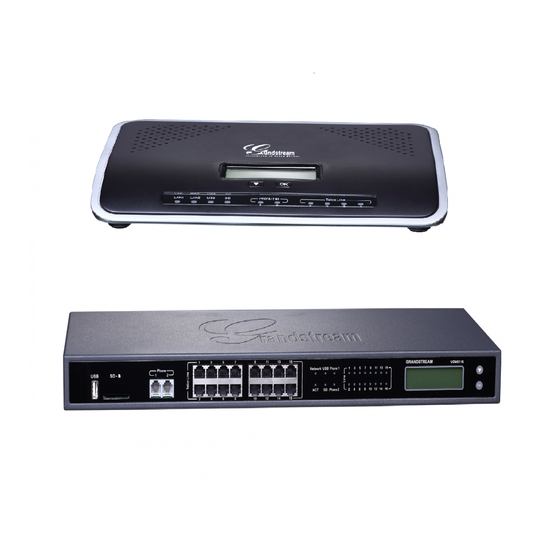
6. (Optional) Connect PSTN lines from the wall jack to the FXO ports; connect analog lines (phone and Fax) to the FXS ports. Connect The UCM6104 Figure 3: UCM6104 Front View P a g e UCM6100 Series User Manual Version 1.0.18.13... -
Page 46: Connect The Ucm6108
LCD shows up the IP address. 6. (Optional) Connect PSTN lines from the wall jack to the FXO ports; connect analog lines (phone and Fax) to the FXS ports. Figure 5: UCM6108 Front View P a g e UCM6100 Series User Manual Version 1.0.18.13... -
Page 47: Connect The Ucm6116
LCD shows up the IP address. 6. (Optional) Connect PSTN lines from the wall jack to the FXO ports; connect analog lines (phone and Fax) to the FXS ports. P a g e UCM6100 Series User Manual Version 1.0.18.13... -
Page 48: Safety Compliances
Grandstream reserves the right to remedy warranty policy without prior notification. ------------------------------------------------------------------------------------------------------------------ --------------------------------- Warning: Use the power adapter provided with the UCM6100 series IP PBX. Do not use a different power adapter as this may damage the device. This type of damage is not covered under warranty. -------------------------------------------------------------------------------------------------------------------------------------------- -------... -
Page 49: Getting Started
This section provides step-by-step instructions on how to use the LCD menu, LED indicators and Web GUI of the UCM6100 series. Once the basic settings are done, users could start making calls from UCM6100 extension registered on a SIP phone as described at the end of this section. -
Page 50: Table 3: Lcd Menu Options
Press "OK" to start. Then press "Down" button to test different LCD patterns. Factory Menu When done, press "OK" button to exit. • Fan Mode Select "Auto" or "On". • LED Test Patterns P a g e UCM6100 Series User Manual Version 1.0.18.13... -
Page 51: Use The Led Indicators
The UCM6100 has LED indicators in the front to display connection status. The following table shows the status definitions. Table 4: UCM6102/UCM6104 LED Indicators LED Indicator LED Status Solid: Connected Flashing: Data Transferring OFF: Not Connected FXS (Phone/Fax) FXO (Telco Line) P a g e UCM6100 Series User Manual Version 1.0.18.13... -
Page 52: Use The Web Gui
The UCM6100 embedded Web server responds to HTTP/HTTPS GET/POST requests. Embedded HTML pages allow users to configure the device through a Web browser such as Microsoft IE, Mozilla Firefox, Google Chrome. P a g e UCM6100 Series User Manual Version 1.0.18.13... -
Page 53: Figure 9: Ucm6102 Web Gui Login Page
It is highly recommended to change the default password after login for the first time. Older units have default password “admin”. See below pictures for the location of the default random password: P a g e UCM6100 Series User Manual Version 1.0.18.13... -
Page 54: Setup Wizard
Once the setup is completed, the system is ready to go. P a g e UCM6100 Series User Manual Version 1.0.18.13... -
Page 55: Web Gui Configurations
Value-added Features: Zero Config, enable CTI server, CRM, PMS WebRTC. Web GUI Languages Currently the UCM6100 series Web GUI supports English, Simplified Chinese, Traditional Chinese, Spanish, French, Portuguese, Russian, Italian, Polish, German etc. Users can select the displayed language in Web GUI login page, or at the upper right of the Web GUI after logging in. -
Page 56: Save And Apply Changes
Password once you hear "Password" voice prompt. 5. Once successfully logged in to the voicemail, you will be prompted with the Voice Mail Main menu. 6. You are successfully connected to the PBX system now. P a g e UCM6100 Series User Manual Version 1.0.18.13... -
Page 57: System Settings
Upload private key for the built-in http server. TLS Private Key Note: The size of the key file must be under 2MB and the it will be renamed as "private.pem" automatically. P a g e UCM6100 Series User Manual Version 1.0.18.13... -
Page 58: Network Settings
WAN port interface will be used for uplink connection. LAN port interface will Method be used to serve as router. • Switch WAN port interface will be used for uplink connection. LAN port interface will be used as bridge for PC connection. P a g e UCM6100 Series User Manual Version 1.0.18.13... - Page 59 Assign the VLAN tag of the layer 2 QoS packets for LAN port. The default value is 802.1Q/VLAN Tag Layer 2 QoS 802.1p Assign the priority value of the layer 2 QoS packets for LAN port. The default value P a g e UCM6100 Series User Manual Version 1.0.18.13...
- Page 60 Assign the priority value of the layer 2 QoS packets for LAN port. Priority Value The default value is 0. IPv6 Address WAN (when "Method" is set to "Route") IP Method Select Auto or Static. The default setting is Auto P a g e UCM6100 Series User Manual Version 1.0.18.13...
- Page 61 Users will need assign the default interface to be LAN 1 (mapped to UCM6102 Default Interface WAN port) or LAN 2 (mapped to UCM6102 LAN port) and then configure network settings for LAN 1/LAN 2. The default interface is LAN 2. P a g e UCM6100 Series User Manual Version 1.0.18.13...
-
Page 62: Table 8: Ucm6104 Network Settings→Basic Settings
Assign the VLAN tag of the layer 2 QoS packets for LAN port. The default value is 802.1Q/VLAN Tag Layer 2 QoS 802.1p Assign the priority value of the layer 2 QoS packets for LAN port. The default value Priority Value is 0. P a g e UCM6100 Series User Manual Version 1.0.18.13... -
Page 63: Table 9: Ucm6108/Ucm6116 Network Settings→Basic Settings
DNS Server 2 Enter the DNS server 2 address for static settings. Table 9: UCM6108/UCM6116 Network Settings→Basic Settings Specifies the Maximum Transmission Unit. (By default, it is 1500) IPv4 Address P a g e UCM6100 Series User Manual Version 1.0.18.13... - Page 64 When the UCM6102 has method set to Route in network settings, WAN port interface is used for uplink connection and LAN port interface is used as a router. Please see a sample diagram below. P a g e UCM6100 Series User Manual Version 1.0.18.13...
-
Page 65: Figure 12: Ucm6102 Network Interface Method: Route
Figure 12: UCM6102 Network Interface Method: Route P a g e UCM6100 Series User Manual Version 1.0.18.13... -
Page 66: Figure 13: Ucm6102 Network Interface Method: Switch
LAN 1 interface; LAN port will be mapped to LAN 2 interface. Users will need assign LAN 1 or LAN 2 as the default interface in option "Default Interface" and configure "Gateway IP" if static IP is used for this interface. P a g e UCM6100 Series User Manual Version 1.0.18.13... -
Page 67: Dhcp Client List
Settings→Network Settings→DHCP Client List” as shown below. Figure 15: DHCP Client List User can bind manually a MAC to an IP address by clicking on , the following figure will pop P a g e UCM6100 Series User Manual Version 1.0.18.13... -
Page 68: Figure 16: Add Mac Address Bind
802.1X as a supplicant/client to be authenticated. The following diagram and figure show UCM6100 uses 802.1X mode “EAP-MD5” on WAN port as client in the network to access Internet. P a g e UCM6100 Series User Manual Version 1.0.18.13... -
Page 69: Figure 18: Ucm6100 Using 802.1X As Client
RADIUS server. If “EAP-TLS” or “EAP-PEAPv0/MSCHAPv2” is used as the 802.1X mode, users will also need upload 802.1X CA Certificate and 802.1X Client Certificate, which should be also generated from the RADIUS server. P a g e UCM6100 Series User Manual Version 1.0.18.13... -
Page 70: Static Routes
Example: IPv4 address - 192.168.66.4 IPv6 subnet - 2001:740:D::1/64 Configure the subnet mask for the above destination IPv4 address. If left blank, the default value is 255.255.255.255. Netmask Example: 255.255.255.0 P a g e UCM6100 Series User Manual Version 1.0.18.13... -
Page 71: Figure 20: Ucm6104 Static Route Sample
Network 192.168.40.0 has IP phones registered to UCM6104 LAN 2 address • Network 192.168.66.0 has IP phones registered to UCM6104 via VPN • Network 192.168.40.0 has VPN connection established with network 192.168.66.0 P a g e UCM6100 Series User Manual Version 1.0.18.13... -
Page 72: Port Forwarding (Ucm6102 Only)
WAN port will be forwarded to the LAN port with the same port number, for example, WAN port 1000 will be port forwarding to LAN port 1000. LAN IP Specify the LAN IP address. P a g e UCM6100 Series User Manual Version 1.0.18.13... -
Page 73: Figure 22: Create New Port Forwarding
LAN Port: This is the port opened up on the GXP2160 side for access purpose. Protocol Type: We select TCP here for Web GUI access using HTTP. Figure 22: Create New Port Forwarding P a g e UCM6100 Series User Manual Version 1.0.18.13... -
Page 74: Openvpn
Open VPN settings allow the users to configure UCM6100 to use VPN features. Table 13: UCM6100 System Settings→OpenVPN Enable Enable / Disable the OpenVPN feature. Server Address Configures the hostname/IP and port of the server. For example: 192.168.1.2:22 P a g e UCM6100 Series User Manual Version 1.0.18.13... -
Page 75: Figure 25: Openvpn Feature On The Ucm6100
Upload a client certificate. This file will be renamed as ‘cliend.crt’ automatically. Client Key Upload a client private key. This file will be renamed as ‘client.key’ automatically. Figure 25: OpenVPN feature on the UCM6100 P a g e UCM6100 Series User Manual Version 1.0.18.13... -
Page 76: Ddns Settings
1. Register domain in DDNS service provider. Please note the UCM6100 needs to have public IP access. Figure 26: Register Domain Name on noip.com 2. On Web GUI→System Settings→Network Settings→DDNS Settings, enable DDNS service and configure username, password and host name. P a g e UCM6100 Series User Manual Version 1.0.18.13... -
Page 77: Figure 27: Ucm6100 Ddns Setting
Figure 27: UCM6100 DDNS Setting 3. Now you can use domain name instead of IP address to connect to the UCM6100 Web GUI. Figure 28: Using Domain Name to Connect to UCM6100 P a g e UCM6100 Series User Manual Version 1.0.18.13... -
Page 78: Security Settings
UCM6100 zero_config service 5060 Asterisk UDP/IPv4 4569 Asterisk UDP/IPv4 5353 zero_config UDP/IPv4 UCM6100 zero_config service 37435 Syslogd UDP/IPv4 Syslog For typical firewall settings, users could configure the following options on the UCM6100. P a g e UCM6100 Series User Manual Version 1.0.18.13... -
Page 79: Table 15: Typical Firewall Settings
"Reject Rules" will be allowed to check: • Action: "Accept" • Type "In" • Destination port is set to the system login port (e.g., by default 8089) • Protocol is not UDP P a g e UCM6100 Series User Manual Version 1.0.18.13... -
Page 80: Table 16: Firewall Rule Settings
Destination (IP and port) and Protocol (TCP, UDP or Both) for the service. Please note if the source or the destination field is left blank, it will be used as "Anywhere". P a g e UCM6100 Series User Manual Version 1.0.18.13... -
Page 81: Dynamic Defense
Dynamic Defense Dynamic defense is supported on the UCM6100 series. It can blacklist hosts dynamically when the LAN mode is set to "Route" under Web GUI→System Settings→Network Settings→Basic Settings page. If enabled, the traffic coming into the UCM6100 can be monitored, which helps prevent massive connection attempts or brute force attacks to the device. -
Page 82: Fail2Ban
REGISTER, INVITE and SUBSCRIBE. Once the entry is detected within "Max Retry Duration", the UCM6100 will act to forbid the host for certain period as defined in "Banned Duration". This feature helps prevent SIP brute force attacks to the PBX system. P a g e UCM6100 Series User Manual Version 1.0.18.13... -
Page 83: Table 18: Fail2Ban Settings
UCM6100. Configure the duration (in seconds) for the detected host to be banned. The default Banned Duration setting is 600. If set to 0, the host will be always banned. P a g e UCM6100 Series User Manual Version 1.0.18.13... -
Page 84: Ssh Access
GUI or LCD screen. For web SSH access, please log in UCM6100 web interface and go to Web GUI→System Settings→Security Settings→SSH Access. By default, SSH access is disabled for security concerns. It is highly recommended to only enable SSH access for debugging purpose. Figure 32: SSH Access P a g e UCM6100 Series User Manual Version 1.0.18.13... -
Page 85: Ldap Server
UCM can also act as a LDAP client to download phonebook entries from another LDAP server. To access LDAP server and client settings, go to Web GUI→Settings→LDAP Server. LDAP Server Configurations The following figure shows the default LDAP server configurations on the UCM6100. P a g e UCM6100 Series User Manual Version 1.0.18.13... -
Page 86: Figure 33: Ldap Server Configurations
LDAP information. The default phonebook list in this LDAP server can be viewed and edited by clicking on for the first phonebook under LDAP Phonebook. Figure 34: Default LDAP Phonebook DN P a g e UCM6100 Series User Manual Version 1.0.18.13... -
Page 87: Ldap Phonebook
GUI→Extension/Trunk→Extensions first. The default LDAP phonebook will then be updated automatically. Figure 36: LDAP Server→LDAP Phonebook • Add new phonebook A new sibling phonebook of the default PBX phonebook can be added by clicking on "Add" under "LDAP Phonebook" section. P a g e UCM6100 Series User Manual Version 1.0.18.13... -
Page 88: Figure 37: Add Ldap Phonebook
Figure 38: Edit LDAP Phonebook • Import phonebook from your computer to LDAP server Click on “Import Phonebook” and a dialog will prompt as shown in the figure below. Figure 39: Import Phonebook P a g e UCM6100 Series User Manual Version 1.0.18.13... -
Page 89: Figure 40: Phonebook Csv File Format
As the default LDAP phonebook with DN “ou=pbx,dc=pbx,dc=com” cannot be edited or deleted in LDAP phonebook section, users cannot import contacts with Phonebook DN field “pbx” if existed in the CSV file. P a g e UCM6100 Series User Manual Version 1.0.18.13... -
Page 90: Ldap Client Configurations
LDAP Name Attributes: Enter the name attributes for remote server • LDAP Number Attributes: Enter the number attributes for remote server The following figure gives a sample configuration for UCM6510 acting as a LDAP client. P a g e UCM6100 Series User Manual Version 1.0.18.13... -
Page 91: Figure 43: Ldap Client Configurations
LDAP Version: If existed, please select LDAP Version 3 • Port: 389 The following figure shows the configuration information on a Grandstream GXP2170 to successfully use the LDAP server as configured in [Figure 33: LDAP Server Configurations]. P a g e UCM6100 Series User Manual Version 1.0.18.13... -
Page 92: Time Settings
The current system time on the UCM6100 can be found under Web GUI→System Status→Dashboard→PBX Status. To configure the UCM6100 to update time automatically, go to Web GUI→System Settings→Time Settings→Auto Time Updating. P a g e UCM6100 Series User Manual Version 1.0.18.13... -
Page 93: Table 19: Time Auto Updating
Prime Meridian (A.K.A: International or Greenwich Meridian); If it is negative (-), the local time zone is east. M4.1.0,M11.1.0 The 1st number indicates Month: 1,2,3.., 12 (for Jan, Feb, .., Dec). P a g e UCM6100 Series User Manual Version 1.0.18.13... -
Page 94: Set Time Manually
UCM6100 as the NTP server, set "Enable NTP server" to "Yes" under Web GUI→System Settings→Time Settings→NTP Server. On the client side, point the NTP server address to the UCM6100 IP address or host name to use the UCM6100 as the NTP server. P a g e UCM6100 Series User Manual Version 1.0.18.13... -
Page 95: Office Time
Once done, click on "Save" and then "Apply Change" for the office time to take effect. The office time will be listed in the web page as the figure shows below. P a g e UCM6100 Series User Manual Version 1.0.18.13... -
Page 96: Holiday
To configure holiday, go to Web GUI→System Settings→Time Settings→Holiday. Click on "Create New Holiday" to create holiday time. Figure 48: Create New Holiday P a g e UCM6100 Series User Manual Version 1.0.18.13... -
Page 97: Table 21: Create New Holiday
Click on "Delete Selected Holidays" to delete multiple selected holidays at once. ----------------------------------------------------------------------------------------------------------------------------- --------------- Note: For more details on how to use office time and holiday, please refer to the link below: http://www.grandstream.com/sites/default/files/Resources/office_time_and_holiday_on_ucm6xxx.pdf -------------------------------------------------------------------------------------------------------------------------------------------- P a g e UCM6100 Series User Manual Version 1.0.18.13... -
Page 98: Email Settings
The UCM will extract the attachments of detected emails and send it to the XXX extension by fax. The attachment must be in PDF/TIF/TIFF format. Note: This field will appear when using Type “Client”. P a g e UCM6100 Series User Manual Version 1.0.18.13... -
Page 99: Figure 50: Ucm6100 Email Settings
Sender For example: pbx@example.mycompany.com. The following figure shows a sample Email setting on the UCM6100, assuming the Email is using 192.168.6.202 as the SMTP server. Figure 50: UCM6100 Email Settings P a g e UCM6100 Series User Manual Version 1.0.18.13... -
Page 100: Email Templates
Press to reset all email templates to default ones. To configure the email template, click the button under Options column, and edit the template as desired. P a g e UCM6100 Series User Manual Version 1.0.18.13... -
Page 101: Email Send Log
Under UCM Web GUI→System Settings→Email Settings→Email Send Log, users could search, filter and check whether the Email is sent out successfully or not. This page will also display the corresponding error message if the Email is not sent out successfully. P a g e UCM6100 Series User Manual Version 1.0.18.13... -
Page 102: Table 23: Email Log
Enter the email code to filter with Email Send Module Select the email module to filter with from the drop-down list, which contains: All Modules Extension Voicemail Conference Schedule User Password Alert Events Test P a g e UCM6100 Series User Manual Version 1.0.18.13... -
Page 103: Figure 54: Email Logs
Email logs will be shown on bottom of the “Email Send Log” page, as shown on the following figure. Figure 54: Email Logs P a g e UCM6100 Series User Manual Version 1.0.18.13... -
Page 104: Provisioning
Each layer also has its own structure in different levels. Please see figure below. The details for each layer are explained in sections Global configuration Model configuration Device Configuration P a g e UCM6100 Series User Manual Version 1.0.18.13... -
Page 105: Auto Provisioning Settings
Grandstream end point devices in the same LAN area in a centralized way. Auto Provisioning Settings By default, the Zero Config feature is enabled on the UCM6100 for auto provisioning. Three methods of auto provisioning are used. P a g e UCM6100 Series User Manual Version 1.0.18.13... -
Page 106: Figure 56: Ucm6100 Zero Config
The phone will then send TFTP request to download the XML config file from the UCM6100. To start the auto provisioning process, under Web GUI→Value-added Features→Zero Config→Zero Config Settings, fill in the auto provision information. P a g e UCM6100 Series User Manual Version 1.0.18.13... -
Page 107: Table 24: Auto Provision Settings
If enabled, when the device is discovered, the PBX will automatically Automatically Assign assign an extension within the range defined in "Zero Config Extension Extension Segment" to the device. The default setting is disabled. P a g e UCM6100 Series User Manual Version 1.0.18.13... -
Page 108: Discovery
Grandstream endpoints are automatically discovered after bootup. Users could also manually discover device by specifying the IP address or scanning the entire LAN network. Three methods are supported to scan the devices. • PING • • SIP Message (NOTIFY) P a g e UCM6100 Series User Manual Version 1.0.18.13... -
Page 109: Figure 58: Auto Discover
The following figure shows a list of discovered phones. The MAC address, IP Address, Extension (if assigned), Version, Vendor, Model, Connection Status, Create Config, Options (Edit /Delete /Update /Reboot /Access Device WebGUI) are displayed in the list. Figure 59: Discovered Devices P a g e UCM6100 Series User Manual Version 1.0.18.13... -
Page 110: Uploading Devices List
IP Address: Enter device IP and press Search button. ▪ MAC Address: Enter device MAC and press Search button. ▪ Model: Enter a model name and press Search button. Example: GXP2130. Figure 61: Managing Discovered Devices P a g e UCM6100 Series User Manual Version 1.0.18.13... -
Page 111: Global Configuration
“Options” dropdown list to quickly navigate to the category. The categories are: • Localization: configure display language, data and time. P a g e UCM6100 Series User Manual Version 1.0.18.13... -
Page 112: Table 25: Global Policy Parameters - Localization
Configure the URL or IP address of the NTP server. The SIP end device NTP Server may obtain the date and time from the server. Time Zone Configure the time zone used on the SIP end device. P a g e UCM6100 Series User Manual Version 1.0.18.13... -
Page 113: Table 26: Global Policy Parameters - Phone Settings
• If “PBX” is selected, the LDAP configuration built-in from UCM6100 Web GUI→System Settings→LDAP Server will be applied. Address Configure the IP address or DNS name of the LDAP server. P a g e UCM6100 Series User Manual Version 1.0.18.13... - Page 114 Configure to enable LDAP number searching when receiving calls. The Incoming Calls default setting is No. Configure to enable LDAP number searching when making calls. The Outgoing Calls default setting is No. P a g e UCM6100 Series User Manual Version 1.0.18.13...
-
Page 115: Table 28: Global Policy Parameters - Maintenance
Firmware can be uploaded to the UCM6100 internal storage for firmware upgrade. If selected, click on “Manage Storage” icon next to “Directory” option, upload firmware file and select directory for the end device to retrieve the firmware file. P a g e UCM6100 Series User Manual Version 1.0.18.13... - Page 116 Configure the administrator password for admin level login. End-User Password Configure the end-user password for the end user level login. Web Access Mode Select HTTP or HTTPS as the web access protocol. P a g e UCM6100 Series User Manual Version 1.0.18.13...
-
Page 117: Table 29: Global Policy Parameters - Network Settings
Specify how often the phone will send a blank UDP packet to the SIP server Keep Alive Interval in order to keep the “ping hole” on the NAT router to open. Valid range is 10-160. P a g e UCM6100 Series User Manual Version 1.0.18.13... -
Page 118: Table 30: Global Policy Parameters - Customization
File If “URL” is selected as source, specify the URL of the wallpaper file. If “Local UCM Server” is selected as source, click to upload wallpaper file to the UCM6100. P a g e UCM6100 Series User Manual Version 1.0.18.13... -
Page 119: Table 31: Global Policy Parameters - Communication Settings
Storage Server Type Either FTP or Central Storage • Server FTP server address • Port FTP port to be used • User Name FTP user name • Path FTP Directory path P a g e UCM6100 Series User Manual Version 1.0.18.13... -
Page 120: Global Templates
Users could then select the options to be modified and click on “Add Option” to add it into the global template. P a g e UCM6100 Series User Manual Version 1.0.18.13... -
Page 121: Figure 63: Edit Global Template
“Delete Selected Templates” to delete multiple selected templates at once. • Click on “Toggle Selected Template(s)” to toggle the status between enabled/disabled for the selected templates. P a g e UCM6100 Series User Manual Version 1.0.18.13... -
Page 122: Model Configuration
Active Check this option to enable the model template. • Click on to edit the model template. P a g e UCM6100 Series User Manual Version 1.0.18.13... -
Page 123: Figure 64: Edit Model Template
English. For P value information of different models, please refer to configuration template here http://www.grandstream.com/support/tools. Figure 64: Edit Model Template • Click on Save when done. The model template will be displayed on Web GUI→Value-added Features→Zero Config→Model Templates page. P a g e UCM6100 Series User Manual Version 1.0.18.13... -
Page 124: Model Update
Model template package can be manually uploaded from local device through Web GUI. Please contact Grandstream customer support if the model package is needed for manual uploading. P a g e UCM6100 Series User Manual Version 1.0.18.13... -
Page 125: Device Configuration
Line Keys and Multiple-Purposed Keys if supported on the selected model. 3. Click on “Create New Device” to save the configuration for this device. P a g e UCM6100 Series User Manual Version 1.0.18.13... -
Page 126: Manage Devices
MPK settings; “Advanced” settings allow users to configure more details in a five-level structure. P a g e UCM6100 Series User Manual Version 1.0.18.13... -
Page 127: Figure 69: Edit Device
If the same option exists on multiple selected global templates, the value in the template with higher priority will override the one in the template with lower priority. Click on to remove the global template from the selected list. P a g e UCM6100 Series User Manual Version 1.0.18.13... - Page 128 (5) Customize Device Settings This is the highest level configuration for the device. Click on “Modify Customize Device Settings” and following dialog will show. P a g e UCM6100 Series User Manual Version 1.0.18.13...
-
Page 129: Figure 70: Edit Customize Device Settings
LCD is set to English. The warning information on right tells that the option matching the P value number exists and clicking on it will lead to the matching option. For P value information of different models, please refer to configuration template here http://www.grandstream.com/sites/default/files/Resources/config-template.zip. P a g e UCM6100 Series User Manual Version 1.0.18.13... -
Page 130: Figure 71: Add P Value In Customize Device Settings
If selected devices are of the same model, the configuration dialog is like the following figure. Configurations in five levels are all available for users to modify. P a g e UCM6100 Series User Manual Version 1.0.18.13... -
Page 131: Figure 72: Modify Selected Devices - Same Model
If selected devices are of different models, the configuration dialog is like the following figure. Click on view more devices of other models. Users are only allowed to make modifications in Global Templates and Global Policy level. P a g e UCM6100 Series User Manual Version 1.0.18.13... -
Page 132: Figure 73: Modify Selected Devices - Different Models
NOTIFY to the SIP end point device and trigger the provisioning process. The device will start downloading the generated configuration file from the URL contained in the NOTIFY message. P a g e UCM6100 Series User Manual Version 1.0.18.13... -
Page 133: Sample Application
1. Go to Web GUI→Value-added Features→Zero Config→Zero Config Settings, select “Enable Zero Config”. 2. Go to Web GUI→Value-added Features→Zero Config→Global Policy, configure Date Format, Time Format and Firmware Source as follows. P a g e UCM6100 Series User Manual Version 1.0.18.13... -
Page 134: Figure 75: Zero Config Sample - Global Policy
“Default Model Template” to make it the default model template. 4. Go to Web GUI→Value-added Features→Zero Config→Model Templates, create another model template “Spanish Support Template” for GXP2140. Add option “Language” and set it to “Español”. P a g e UCM6100 Series User Manual Version 1.0.18.13... -
Page 135: Figure 76: Zero Config Sample - Device Preview 1
8. For the 3 phones used by Spanish support, in “Basic” settings select an available extension for account 1 and click on “Save”. Then click on “Advanced” settings tab to bring up the following dialog. P a g e UCM6100 Series User Manual Version 1.0.18.13... -
Page 136: Figure 77: Zero Config Sample - Device Preview 2
9. For the GXV3275 used by the customer support supervisor, select an available extension for account 1 on “Basic” settings and click on “Save”. Users can see the preview of the device configuration in “Advanced” settings. There is no model template configured for GXV3275. P a g e UCM6100 Series User Manual Version 1.0.18.13... -
Page 137: Figure 78: Zero Config Sample - Device Preview 3
Spanish on LCD and the other 5 will be provisioned to display English on LCD. The GXV3275 used by the supervisor will be provisioned to use the default language on LCD display since it’s not specified in the global policy. P a g e UCM6100 Series User Manual Version 1.0.18.13... -
Page 138: Extensions
Figure 79: Create New Device Extension options are divided into four categories: • Basic Settings • Media • Features • Specific Time P a g e UCM6100 Series User Manual Version 1.0.18.13... -
Page 139: Table 34: Sip Extension Configuration Parameters→Basic Settings
Note: When set to “Default”, the global settings in Call Features → Voicemail → Voicemail Email Settings will be used. Keep Voicemail Whether to keep the local voicemail recording after sending them. If set to “Default”, P a g e UCM6100 Series User Manual Version 1.0.18.13... -
Page 140: Table 35: Sip Extension Configuration Parameters→Media
NAT (e.g., broadband router). If there is one-way audio issue, usually it's related to NAT configuration or Firewall's support of SIP and RTP ports. The default setting is enabled. P a g e UCM6100 Series User Manual Version 1.0.18.13... - Page 141 Select audio and video codec for the extension. The available codecs are: PCMU, Codec Preference PCMA, GSM, AAL2-G.726-32, G,726, G.722, G.729, G.723, iLBC, ADPCM, H.264, H.265, H.263, H.263p, RTX and VP8. P a g e UCM6100 Series User Manual Version 1.0.18.13...
-
Page 142: Table 36: Sip Extension Configuration Parameters→Features
“Ring Group”: Select a ring group from dropdown list as CFN target. • “Queues”: Select a queue from dropdown list as CFN target. • “Voicemail Group”: Select a voicemail group from dropdown list as CFN target. The default setting is “None”. P a g e UCM6100 Series User Manual Version 1.0.18.13... - Page 143 Time”, “Out of Office Time”, “Holiday”, “Out of Holiday”, “Out of Office Time or Holiday” and “Specific”. DND Time Condition Notes: • “Specific” has higher priority to “Office Times” if there is a conflict in terms of time period. P a g e UCM6100 Series User Manual Version 1.0.18.13...
- Page 144 Set the external number to be rang simultaneously. ‘-’ is the connection character External Number which will be ignored. This field accepts only letters, numbers, and special characters + = * #. P a g e UCM6100 Series User Manual Version 1.0.18.13...
- Page 145 Extension. Enable LDAP If enabled, the extension will be added to LDAP Phonebook PBX list. Enable WebRTC Enable registration and call from WebRTC. Support P a g e UCM6100 Series User Manual Version 1.0.18.13...
-
Page 146: Create New Iax Extension
"National" and "International" from the lowest level to the highest level. The default Permission setting is "Internal". Note: Users need to have the same level as or higher level than an outbound rule's privilege to make outbound calls using this rule. P a g e UCM6100 Series User Manual Version 1.0.18.13... -
Page 147: Table 39: Iax Extension Configuration Parameters→Media
Token shared between physical endpoints. The default setting is "Yes". SRTP Enable SRTP for the call. The default setting is disabled. P a g e UCM6100 Series User Manual Version 1.0.18.13... -
Page 148: Table 40: Iax Extension Configuration Parameters→Features
Settings→Office Time/Holiday page. Call Forward No Configure the Call Forward No Answer target number. If not configured, the Call Answer Forward No Answer feature is deactivated. The default setting is deactivated. P a g e UCM6100 Series User Manual Version 1.0.18.13... - Page 149 Prompt→Custom Prompt: General Preference. The valid range is between 5 seconds and 600 seconds. Note: If the end point also has a ring timeout configured, the actual ring timeout used is the shortest time set by either device. P a g e UCM6100 Series User Manual Version 1.0.18.13...
-
Page 150: Create New Fxs Extension
Configure the CallerID Number that would be applied for outbound calls from this user. Caller ID Number Note: The ability to manipulate your outbound Caller ID may be limited by your VoIP provider. P a g e UCM6100 Series User Manual Version 1.0.18.13... - Page 151 UCM6100. To add more languages in the list, please download voice prompt package by selecting "Check Prompt List" under Web GUI→PBX Settings→Voice Prompt→Language Settings. P a g e UCM6100 Series User Manual Version 1.0.18.13...
-
Page 152: Table 43: Fxs Extension Configuration Parameters→Media
Email address configured in Fax setting page under Web GUI→Call Features→Fax/T.38. • Fax Gateway: If selected, the UCM6100 can support conversation and processing of Fax data from T.30 to T.38 or T.38 to T.30. only for FXS ports. P a g e UCM6100 Series User Manual Version 1.0.18.13... -
Page 153: Table 44: Fxs Extension Configuration Parameters→Features
Specific time can be configured on the bottom of the extension configuration dialog. Scroll down the add Time Condition for specific time. • Office Time and Holiday could be configured on page System Settings→Time Settings→Office Time/Holiday page. P a g e UCM6100 Series User Manual Version 1.0.18.13... - Page 154 Enable automatic recording for the calls using this extension. The default setting is Auto Record disabled. The recording files can be accessed under Web GUI→CDR→Recording Files. P a g e UCM6100 Series User Manual Version 1.0.18.13...
-
Page 155: Batch Add Extensions
"National" and "International" from the lowest level to the highest level. The default Permission setting is "Internal". Note: Users need to have the same level as or higher level than an outbound rule's privilege to make outbound calls from this rule. P a g e UCM6100 Series User Manual Version 1.0.18.13... - Page 156 Enable automatic recording for the calls using this extension. The default setting is Auto Record disabled. The recording files can be accessed under Web GUI→CDR→Recording Files. P a g e UCM6100 Series User Manual Version 1.0.18.13...
- Page 157 Request-Line and TO header in the SIP request to indicate the E.164 number. If set to "Enable", "Tel:" will be used instead of "SIP:" in the SIP request. The default setting is disabled. P a g e UCM6100 Series User Manual Version 1.0.18.13...
-
Page 158: Batch Add Iax Extensions
Start Extension Configure the starting extension number of the batch of extensions to be added. Create Number Specify the number of extensions to be added. The default setting is 5. P a g e UCM6100 Series User Manual Version 1.0.18.13... - Page 159 By default, this option is disabled. Verification Select which Music On Hold class to suggest to extensions when putting them on Music On Hold hold. P a g e UCM6100 Series User Manual Version 1.0.18.13...
- Page 160 Select audio and video codec for the extension. The available codecs are: PCMU, Codec Preference PCMA, GSM, AAL2-G.726-32, G.722, G.729, G.723, iLBC, ADPCM, LPC10, H.264, H.265, H.263, H.263p and VP8. P a g e UCM6100 Series User Manual Version 1.0.18.13...
-
Page 161: Batch Extension Resetting Functionality
Unavailable (the extension is not registered or disabled on the PBX) • Edit single extension Click on to start editing the extension parameters. • Reset single extension Click on to reset the extension parameters to default (except concurrent registration). P a g e UCM6100 Series User Manual Version 1.0.18.13... -
Page 162: Export Extensions
The exported csv file can serve as a template for users to fill in desired extension information to be imported to the UCM6100. Import Extensions The capability to import extensions to the UCM6100 provides users flexibility to batch add extensions with similar or different configuration quickly into the PBX system. P a g e UCM6100 Series User Manual Version 1.0.18.13... -
Page 163: Table 48: Sip Extensions Imported File Example
6. Click on "Apply Changes" to apply the imported file on the UCM6100. Example of file to import: Figure 83: Import File Table 48: SIP extensions Imported File Example Field Supported values Extension Digits Technology SIP/SIP(WebRTC) P a g e UCM6100 Series User Manual Version 1.0.18.13... - Page 164 Keep-alive Frequency Value from 1-3600 AuthID Alphanumeric value without special characters TEL URI Disabled/user=phone/enabled Call Forward Busy Digits Call Forward No Answer Digits Call Forward Unconditional Digits Support Hot-Desking Mode Yes/no P a g e UCM6100 Series User Manual Version 1.0.18.13...
- Page 165 DND Time Condition All time/Office time/out of office time/holiday/out of holiday/out of office time or holiday/specific time Custom Auto answer Yes/no Do Not Disturb Whitelist Empty/digits User Password Alphanumeric characters. P a g e UCM6100 Series User Manual Version 1.0.18.13...
-
Page 166: Table 49: Iax Extensions Imported File Example
IP address/Mask Local Subnet 8 IP address/Mask Local Subnet 9 IP address/Mask Local Subnet 10 IP address/Mask Specific IP Address IP address Skip Trunk Auth yes/no/bytime Codec Preference PCMU,PCMA,GSM,G.726,G.722,G.729,H.264, H.265,ILBC,AAL2-G.726- 32,ADPCM,G.723,H.263,H.263p,vp8,opus P a g e UCM6100 Series User Manual Version 1.0.18.13... - Page 167 Last Name Alphanumeric without special characters. Email Address Email address Language Default/en/zh Phone Number Digits Call-Barging Monitor Extensions allowed to call barging Seamless Transfer Members Extensions allowed to seamless transfer P a g e UCM6100 Series User Manual Version 1.0.18.13...
-
Page 168: Table 50: Fxs Extensions Imported File Example
All time/Office time/out of office time/holiday/out of holiday/out of office time or holiday/specific time CFB Time Condition All time/Office time/out of office time/holiday/out of holiday/out of office time or holiday/specific time Music On Hold Default/ringbacktone_default P a g e UCM6100 Series User Manual Version 1.0.18.13... -
Page 169: Figure 84: Import Error
The CSV file should contain all the above fields, if one of them is missing or empty, the UCM6100 will display the following error message for missing fields. Figure 84: Import Error P a g e UCM6100 Series User Manual Version 1.0.18.13... -
Page 170: Extension Details
Once the extensions are created with Email addresses, the PBX administrator can click on button “E-mail Notification” to send the account registration and configuration information to the user. Please make sure Email P a g e UCM6100 Series User Manual Version 1.0.18.13... -
Page 171: Figure 86: E-Mail Notification - Prompt Information
Mobile applications to scan it and get automatically provisioned. QR code provisioning is supported on Grandstream Softphone GS Wave Android application and iOS application. Figure 87: Account Registration Information and QR Code P a g e UCM6100 Series User Manual Version 1.0.18.13... -
Page 172: Multiple Registrations Per Extension
Figure 89: Multiple Registrations per Extension This feature enabled configuring option “Concurrent Registrations” under GUI→Extension/Trunk→Edit Extension. The default value is set to 1 for security purpose. Maximum is 10. P a g e UCM6100 Series User Manual Version 1.0.18.13... -
Page 173: Sms Message Support
SMS message. Please refer to the end device documentation on how to send and receive SMS message. SMS Message support is a new feature added since firmware 1.0.10.x which is built with Asterisk 13. Figure 91: SMS Message Support P a g e UCM6100 Series User Manual Version 1.0.18.13... -
Page 174: Extension Groups
Select extensions from the list on the left side to the right side. Figure 92: Edit Extension Group Click on in order to change the ringing priority of the members selected on the group. P a g e UCM6100 Series User Manual Version 1.0.18.13... -
Page 175: Using Extension Groups
Routes and select "Enable Filter on Source Caller ID". Both single extensions and extension groups will show up for users to select. Figure 93: Select Extension Group in Outbound Route P a g e UCM6100 Series User Manual Version 1.0.18.13... -
Page 176: Analog Trunks
For some countries, a polarity reversal is used for Reversal signaling the disconnection of a phone line and the call will be considered as “Hangup” on a polarity reversal. The default setting is “No”. P a g e UCM6100 Series User Manual Version 1.0.18.13... - Page 177 FXO port. The port order that the call will use to go out would be port 16→port 10→port 2→port 1. Every time it will start with port 16 (if it's idle). The default setting is “Ascend” mode. P a g e UCM6100 Series User Manual Version 1.0.18.13...
- Page 178 PSTN. Before the detecting, please make sure there are more than one channel PSTN Detection configured and working properly. If the detection has busy tone, the "Tone Country" option will be set as "Custom". P a g e UCM6100 Series User Manual Version 1.0.18.13...
-
Page 179: Pstn Detection
Tone Country. The default setting is "United States of America (USA)". • PSTN Detection. Figure 94: UCM6100 FXO Tone Settings 4. Click on "Detect" to start PSTN detection. Figure 95: UCM6100 PSTN Detection P a g e UCM6100 Series User Manual Version 1.0.18.13... -
Page 180: Figure 96: Ucm6100 Pstn Detection: Auto Detect
Figure 96: UCM6100 PSTN Detection: Auto Detect • If there is only one FXO port connected to PSTN line, use the following settings for auto-detection. Figure 97: UCM6100 PSTN Detection: Semi-Auto Detect P a g e UCM6100 Series User Manual Version 1.0.18.13... -
Page 181: Table 52: Pstn Detection For Analog Trunk
Once the detection is successful, the detected parameters "Busy Tone", "Polarity Reversal" and "Current Disconnect by PSTN" will be filled into the corresponding fields in the analog trunk configuration. ----------------------------------------------------------------------------------------------------------------------------- ---------------------- P a g e UCM6100 Series User Manual Version 1.0.18.13... -
Page 182: Voip Trunks
Turn on this setting when the PBX is using public IP and communicating with devices behind NAT. If there is one-way audio issue, usually it is related to NAT configuration or SIP/RTP port support on the firewall. P a g e UCM6100 Series User Manual Version 1.0.18.13... -
Page 183: Table 54: Sip Register Trunk Configuration Parameters
2002 regardless of the configured inbound destination. Table 54: SIP Register Trunk Configuration Parameters Basic Settings Configure a unique label to identify this trunk when listed in outbound rules, Provider Name inbound rules etc. P a g e UCM6100 Series User Manual Version 1.0.18.13... - Page 184 “From” Header. There are cases where there is a single ID for registration (single From User trunk) with multiple DIDs. For example, "1234567" is the From User in From Header: sip:1234567@trunk.UCM6100.provider.com. P a g e UCM6100 Series User Manual Version 1.0.18.13...
- Page 185 “123456”. If “Send PAI Header” is enabled and “PAI Header” is configured as “empty”, the PAI header in the SIP message sent from the UCM will contain the original CID. P a g e UCM6100 Series User Manual Version 1.0.18.13...
- Page 186 The default setting is 60 seconds. Maximum Number of The maximum number of concurrent calls using the trunk. The default settings 0, Call Lines which means no limit. P a g e UCM6100 Series User Manual Version 1.0.18.13...
-
Page 187: Table 55: Sip Peer Trunk Configuration Parameters
If selected, the trunk will be disabled. Note: Disable This Trunk If a current SIP trunk is disabled, UCM will send UNREGISTER message (REGISTER message with expires=0) to the SIP provider. P a g e UCM6100 Series User Manual Version 1.0.18.13... - Page 188 Configure the default DTMF mode when sending DTMF on this trunk. • Default: The global setting of DTMF mode will be used. The global setting DTMF Mode for DTMF Mode setting is under Web GUI→PBX Settings→SIP Settings→ToS. P a g e UCM6100 Series User Manual Version 1.0.18.13...
- Page 189 CC Settings If enabled, the system will automatically alert the user when a called party is Enable CC available, given that a previous call to that party failed for some reason. P a g e UCM6100 Series User Manual Version 1.0.18.13...
-
Page 190: Table 56: Create New Iax Trunk
Important Note: When making outgoing calls, the following priority order rule will be used to determine which CallerID will be set before sending out the call : From user (Register Trunk Only) → CID from inbound call (Keep Original CID P a g e UCM6100 Series User Manual Version 1.0.18.13... -
Page 191: Table 58: Iax Peer Trunk Configuration Parameters
CID configured. The default setting is "No". Disable This Trunk If selected, the trunk will be disabled. Caller ID Configure the Caller ID. This is the number that the trunk will try to use when P a g e UCM6100 Series User Manual Version 1.0.18.13... -
Page 192: Trunk Groups
Users can create VoIP Trunk Groups to register and easily apply the same settings on multiple accounts within the same SIP server. This can drastically reduce the amount of time needed to manage accounts for the same server and improve the overall cleanliness of the web UI. P a g e UCM6100 Series User Manual Version 1.0.18.13... -
Page 193: Figure 98: Trunk Group
Once creating the new trunk group and configuring the SIP settings, users can add multiple accounts within the configured SIP server by pressing button and configuring the username, password and authentication ID fields. Figure 99: Trunk Group Configuration P a g e UCM6100 Series User Manual Version 1.0.18.13... -
Page 194: Direct Outward Dialing (Dod)
In this case, Company ABC would select the CEO's extension. After making the selection, click on the button to move the extension(s) to the "Selected Extensions" list. Figure 100: DOD extension selection P a g e UCM6100 Series User Manual Version 1.0.18.13... -
Page 195: Figure 101: Edit Dod
7. Click "Save" at the bottom. Once completed, the user will return to the EDIT DOD page that shows all the extensions that are associated to a particular DOD. Figure 101: Edit DOD P a g e UCM6100 Series User Manual Version 1.0.18.13... -
Page 196: Sla Station
Configure the time (in seconds) to ring the station before the call is considered Ring Timeout unanswered. No timeout is set by default. If set to 0, there will be no timeout. P a g e UCM6100 Series User Manual Version 1.0.18.13... -
Page 197: Sample Configuration
Users can create one or more SLA [Create/Edit SLA Station] stations to monitor the analog trunk. The following figure shows two stations, 1002 and 1005, are configured to be associated with SLA trunk “fxo1”. P a g e UCM6100 Series User Manual Version 1.0.18.13... -
Page 198: Figure 105: Sla Example - Sla Station
If the external line is previously put on hold by an SLA station, another station that monitors the same SLA trunk could UnHold the call by pressing the BLF key if “Hold Access” is set to “open” on the analog trunk and the SLA station. P a g e UCM6100 Series User Manual Version 1.0.18.13... -
Page 199: Call Routes
Multiple patterns can be used. Each pattern should be entered in new line. ▪ Users can add comments to a dial plan by typing “/*” and “*/” before and after each comment respectively. P a g e UCM6100 Series User Manual Version 1.0.18.13... - Page 200 PBX. 2. Custom Dynamic Route: define the pattern for the source caller ID. This allows users to define extension range instead of selecting them one by one. P a g e UCM6100 Series User Manual Version 1.0.18.13...
- Page 201 Specify the digits to be prepended before the call is placed via the trunk. Those Prepend digits will be prepended after the dialing number is stripped. P a g e UCM6100 Series User Manual Version 1.0.18.13...
-
Page 202: Outbound Blacklist
Figure 107: Country Codes Note: Users can export outbound route blacklists and delete all blacklist entries. Additionally, users can also import blacklists for outbound routes. P a g e UCM6100 Series User Manual Version 1.0.18.13... -
Page 203: Pin Groups
Specify the code that will asked once dialing via a trunk PIN Name Specify the name of the PIN Once user click on the following figure shows to configure the new PIN. P a g e UCM6100 Series User Manual Version 1.0.18.13... -
Page 204: Figure 109: Create New Pin Group
The following screenshot shows an example of created PIN Groups and members: Figure 110: PIN Members Note: If PIN group is enabled on outbound route level, password, privilege level and enable filter on source caller ID will be disabled. P a g e UCM6100 Series User Manual Version 1.0.18.13... -
Page 205: Figure 111: Outbound Pin
User can also import PIN Groups by uploading CSV files for each group. To do this: 1. Navigate to Extension/Trunk→Outbound Routes→PIN Groups and click on the “Choose file to upload” button. P a g e UCM6100 Series User Manual Version 1.0.18.13... -
Page 206: Figure 113: Importing Pin Groups From Csv Files
Select the CSV file to upload. Incorrect file formats and improperly formatted CSV files will result in error messages such as the one below Figure 114: Incorrect CSV File To ensure a successful import, please follow the format in the sample image below P a g e UCM6100 Series User Manual Version 1.0.18.13... -
Page 207: Inbound Routes
• Click on "Blacklist" to configure blacklist for all inbound routes. • Click on to edit the inbound route. • Click on to delete the inbound route. P a g e UCM6100 Series User Manual Version 1.0.18.13... -
Page 208: Inbound Rule Configurations
Allows the selected extension to use this function. If an extension is busy, and a Allowed to Seamless mobile phone is bound to that extension, the mobile phone can pick up calls to that Transfer extension. P a g e UCM6100 Series User Manual Version 1.0.18.13... - Page 209 • Voicemail Groups • Fax Extension • Dial By Name • Select the default destination for the inbound call. • Extension • Default Destination Voicemail • Conference Room • Queue P a g e UCM6100 Series User Manual Version 1.0.18.13...
-
Page 210: Inbound Route: Prepend Example
3. If Prepend is set to 2, UCM6100 will then prepend a 2 to the stripped number, now the number become 2163. 4. UCM6100 will now forward the incoming call to extension 2163. P a g e UCM6100 Series User Manual Version 1.0.18.13... -
Page 211: Inbound Route: Multiple Mode
In the UCM6100, the user can configure inbound route to enable multiple mode to switch between different destinations. The inbound multiple mode can be enabled under Inbound Route settings. Figure 118: Inbound Route - Multiple Mode P a g e UCM6100 Series User Manual Version 1.0.18.13... -
Page 212: Figure 119: Inbound Route - Multiple Mode Feature Codes
“Inbound Routes” page, check “Enable Inbound Multiple Mode” option and change “Inbound Default Mode” and “Inbound Mode 1” values (By default, *61 and *62 respectively). Figure 119: Inbound Route - Multiple Mode Feature Codes P a g e UCM6100 Series User Manual Version 1.0.18.13... -
Page 213: Inbound Route: Inbound Mode Blf Monitoring
Figure 121 : Inbound Mode - Default Mode 5. Pressing the key will toggle the inbound mode to “Mode 1”, and the button’s color will change to red. Figure 122 : Inbound Mode - Mode 1 P a g e UCM6100 Series User Manual Version 1.0.18.13... -
Page 214: Inbound Route: Import/Export Inbound Route
Mode 1: By DID, Extension, Voicemail… User should enter a Default Destination string following the values we have in the mode 1 Default Destination list. • Mode 1 Destination: An Extension number, Ring Group Extension… • Mode 1 Time Condition. P a g e UCM6100 Series User Manual Version 1.0.18.13... -
Page 215: Fax Intelligent Route
• User can also export the inbound route black list by pressing on button. Figure 124: Blacklist Configuration Parameters P a g e UCM6100 Series User Manual Version 1.0.18.13... -
Page 216: Figure 125: Blacklist Csv File
Users could also add a number to the Blacklist or remove a number from the Blacklist by dialing the feature code for "Blacklist Add' (default: *40) and "Blacklist Remove" (default: *41) from an extension. The feature code can be configured under Web GUI→Call Features→Feature Codes. ----------------------------------------------------------------------------------------------------------------------------- ---------------------- P a g e UCM6100 Series User Manual Version 1.0.18.13... -
Page 217: Conference Room
Admin Password the invited party) during the conference call. Note: • If "Public Mode" is enabled, the password is not required to join the conference room thus this field is invalid. P a g e UCM6100 Series User Manual Version 1.0.18.13... - Page 218 The default setting is "No". Select the music on hold class to be played in conference call. Music On Hold Music On Hold class can be set up under Web GUI→PBX Settings→Music On Hold. P a g e UCM6100 Series User Manual Version 1.0.18.13...
-
Page 219: Join A Conference Call
Users can check the talking Caller IDs in conference control page (UCM WebUI→Call Features→Conference). The image will move up and down when the user is talking. Figure 126: Conference Join a Conference Call P a g e UCM6100 Series User Manual Version 1.0.18.13... -
Page 220: Invite Other Parties To Join Conference
0: If 0 is entered to invite other party, once the invited party picks up the invitation call, a permission will be asked to "accept" or "reject" the invitation before joining the conference. 1: If 1 is entered to invite other party, no permission will be required from the invited party. --------------------------------------------------------------------------------------------------------------------------------------------------- P a g e UCM6100 Series User Manual Version 1.0.18.13... -
Page 221: During The Conference
Kick the last joined user from the conference. Decrease the volume of the conference call. Decrease your volume. Increase the volume of the conference call. Increase your volume. More options. P a g e UCM6100 Series User Manual Version 1.0.18.13... -
Page 222: Conference Schedule Configuration
After the user configures UCM6100 with Google Service Settings [Google Service Settings Support] and enables Google Calendar for Conference Schedule, the conference schedule on the UCM6100 can be synchronized with Google Calendar for authorized Google account. Table 66: Conference Schedule Parameters Schedule Options P a g e UCM6100 Series User Manual Version 1.0.18.13... - Page 223 “Public Mode” is enabled, this option is automatically disabled. If this option is enabled, conference participants will be able to access conference Enable Caller Menu room menu by pressing the * key. P a g e UCM6100 Series User Manual Version 1.0.18.13...
- Page 224 If this option is enabled, the invitation from Web GUI via a trunk with password When Inviting Users won’t require authentication. via Trunk from Web Note: Please be aware of the potential security risks when turning on this option. • Cleaner Options P a g e UCM6100 Series User Manual Version 1.0.18.13...
-
Page 225: Figure 128: Conference Schedule
Enter the clean interval (in days). The valid range is from 1 to 30. • Show/hide Conference Schedule Table Enable this option will allow Web GUI to display scheduled conference in Conference Schedule Table. Please see figure below. Figure 128: Conference Schedule P a g e UCM6100 Series User Manual Version 1.0.18.13... -
Page 226: Google Service Settings Support
If you do not have OAuth2.0 project set up yet, please following the steps below to create new project and obtain credentials: 1. Go to Google Developers page https://console.developers.google.com/start Create a New Project in Google Developers page. P a g e UCM6100 Series User Manual Version 1.0.18.13... -
Page 227: Figure 130: Google Service→New Project
Figure 131: Google Service→Create New Credential 4. Use the newly created login credential to fill in “OAuth2.0 Client ID” and “OAuth2.0 Client Secret”. 5. Click “Get Authentication Code” to obtain authentication code from Google Service. P a g e UCM6100 Series User Manual Version 1.0.18.13... -
Page 228: Record Conference
Users could also delete all recording files by clicking on “Delate All Recording Files”, or delete multiple recording files at once by clicking on “Delete Selected Recording Files” after selecting the recording files. P a g e UCM6100 Series User Manual Version 1.0.18.13... -
Page 229: Figure 133: Conference Recording
Figure 133: Conference Recording P a g e UCM6100 Series User Manual Version 1.0.18.13... -
Page 230: Ivr
Click on "Create New IVR" to add a new IVR. • Click on to edit the IVR configuration. • Click on to delete the IVR. Figure 134: Create New IVR P a g e UCM6100 Series User Manual Version 1.0.18.13... -
Page 231: Table 67: Ivr Configuration Parameters
UAS. Select an audio file to play as the welcome prompt for the IVR. Click on "Prompt" Welcome Prompt additional audio file under GUI→PBX Settings→Voice Prompt→Custom Prompt. P a g e UCM6100 Series User Manual Version 1.0.18.13... - Page 232 • Page Group Press 6 • Press 7 • Custom Prompt Press 8 • Hangup Press 9 • DISA Press * • Dial by Name • External Number • Callback P a g e UCM6100 Series User Manual Version 1.0.18.13...
-
Page 233: Black/White List In Ivr
To use this feature, log in UCM Web GUI and navigate to Call Features→IVR→Create/Edit IVR: IVR Black/White List. • If the user selects “Blacklist Enable” and adds extension in the list, the extensions in the list will not be allowed to be reached via IVR. P a g e UCM6100 Series User Manual Version 1.0.18.13... -
Page 234: Figure 136: Black/White List
If the user selects “Whitelist Enable” and adds extension in the list, only the extensions in the list can be allowed to be reached via IVR. Figure 136: Black/White List P a g e UCM6100 Series User Manual Version 1.0.18.13... -
Page 235: Create Custom Prompt
Figure 137: Click on Prompt to Create IVR Prompt Once the IVR prompt file is successfully added to the UCM6100, it will be added into the prompt list options for users to select in different IVR scenarios. P a g e UCM6100 Series User Manual Version 1.0.18.13... -
Page 236: Language Settings For Voice Prompt
Download and Install Voice Prompt Package To download and install voice prompt package in different languages from UCM6100 Web GUI, click on "Check Prompt List" button. Figure 138: Language Settings for Voice Prompt P a g e UCM6100 Series User Manual Version 1.0.18.13... -
Page 237: Figure 139: Voice Prompt Package List
Figure 140: New Voice Prompt Language Added A new language option will be displayed after successfully installed. Users then could select it to apply in the UCM6100 system voice prompt or delete it from the UCM6100. P a g e UCM6100 Series User Manual Version 1.0.18.13... -
Page 238: Customize Specific Prompt
On the UCM6100, if the user needs to replace some specific customized prompt, the user can upload a single specific customized prompt from Web GUI→PBX Settings→Voice Prompt→Language Settings instead of the entire language pack. Figure 141: Upload Single Voice Prompt for Entire Language Pack P a g e UCM6100 Series User Manual Version 1.0.18.13... -
Page 239: Voicemail
Configure Voicemail If the voicemail is enabled for UCM6100 extensions, the configurations of the voicemail can be globally set up and managed under Web GUI→Call Features→Voicemail. Figure 142: Voicemail Settings P a g e UCM6100 Series User Manual Version 1.0.18.13... -
Page 240: Table 68: Voicemail Settings
If enabled, UCM will play from the voice message left most recently; if disabled, Play from Last UCM will play from the earliest left voice message Allow User Review If enabled, users can review the message following the IVR before sending. P a g e UCM6100 Series User Manual Version 1.0.18.13... -
Page 241: Access Voicemail
4 - Leave a message * - Return to the main menu 5 - Repeat the current message 7 - Delete this message 8 - Forward the message to another user 9 - Save P a g e UCM6100 Series User Manual Version 1.0.18.13... -
Page 242: Leaving Voicemail
In case if the caller is calling from an internal extension, they will be directly forwarded to the extension’s voicemail box. But if the caller is calling from outside the system and the incoming call is routed by DID to the P a g e UCM6100 Series User Manual Version 1.0.18.13... -
Page 243: Extension Voicemail Count
If enabled, voicemails will be sent to user's Email address. The default setting E-Mail is "Yes". If enabled, voicemail will be stored in the UCM6100 after the email is sent. The Keep Recordings default setting is “Yes”. P a g e UCM6100 Series User Manual Version 1.0.18.13... -
Page 244: Configure Voicemail Group
The UCM6100 supports voicemail group and all the extensions added in the group will receive the voicemail to group extension. voicemail group configured under GUI→Call Features→Voicemail→Voicemail Group. Click on "Create New Voicemail Group" to configure the group. P a g e UCM6100 Series User Manual Version 1.0.18.13... -
Page 245: Table 71: Voicemail Group Settings
Voicemail Group Select available mailboxes from the left list and add them to the right list. The Mailboxes extensions need to have voicemail enabled to be listed in available mailboxes list. P a g e UCM6100 Series User Manual Version 1.0.18.13... -
Page 246: Ring Group
Ring all the members at the same time when there is incoming call to the ring group extension. If any of the member answers the call, it will stop ringing. P a g e UCM6100 Series User Manual Version 1.0.18.13... - Page 247 PIN-protected and requires authentication, the other ring group members will no longer receive the call after it is forwarded. • If the forwarded call hits voicemail, the other ring group members will no longer receive the call. P a g e UCM6100 Series User Manual Version 1.0.18.13...
-
Page 248: Figure 147: Ring Group Configuration
Enable Destination Secret and Email address are required if voicemail is selected as the destination. Figure 147: Ring Group Configuration P a g e UCM6100 Series User Manual Version 1.0.18.13... -
Page 249: Remote Extension In Ring Group
Password must match for UCM6100_A and UCM6100_B to sync LDAP contact automatically. Port number can be anything between 0~65535, and use the outbound rule created in step 1 for the LDAP Outbound Rule option. P a g e UCM6100 Series User Manual Version 1.0.18.13... -
Page 250: Figure 148: Sync Ldap Server Option
3. In case if LDAP server doesn’t sync automatically, user can manually sync LDAP server. Under VoIP Trunks page, click sync button shown in the following figure to manually sync LDAP contacts from peer UCM6100. P a g e UCM6100 Series User Manual Version 1.0.18.13... -
Page 251: Figure 149: Manually Sync Ldap Server
Please also make sure the extensions in the peer UCM6100 can be included into that UCM6100’s LDAP contact. Figure 150: Ring Group Remote Extension P a g e UCM6100 Series User Manual Version 1.0.18.13... -
Page 252: Paging And Intercom Group
This section describes the configuration of paging/intercom group under Web GUI→Call Features→Paging/Intercom. Configure Paging/Intercom Group • Click on "Create New Paging/Intercom Group" to add paging/intercom group. Figure 151: Paging/Intercom Group P a g e UCM6100 Series User Manual Version 1.0.18.13... -
Page 253: Table 73: Paging/Intercom Group Configuration Parameters
Intercom Prefix is *80. To edit page/intercom feature code, click on "Feature Codes" in the "Paging/Intercom Group Settings" dialog. Or users could go to Web GUI→Call Features→Feature Codes directly. P a g e UCM6100 Series User Manual Version 1.0.18.13... -
Page 254: Configure A Scheduled Paging / Intercom
Select the type for the scheduled paging / intercom call. The available types are: Type Single time or Daily basis. Default is “Single”. Display the action status of the scheduled paging / intercom call. Action Status P a g e UCM6100 Series User Manual Version 1.0.18.13... -
Page 255: Figure 154: Creating A Scheduled Paging/Intercom Call
Figure 154: Creating a scheduled paging/intercom call P a g e UCM6100 Series User Manual Version 1.0.18.13... -
Page 256: Call Queue
Name Configure the call queue name to identify the call queue. Select the strategy for the call queue. Strategy • Ring All Ring all available Agents simultaneously until one answers. P a g e UCM6100 Series User Manual Version 1.0.18.13... - Page 257 Cycle key to transfer to failover destination. Custom Prompt When playing a custom prompt, press 1 to transfer to failover destination. P a g e UCM6100 Series User Manual Version 1.0.18.13...
- Page 258 • Play Sound. • Extension. • Failover Destination Voicemail. • Queues. • Ring Group. • Voicemail Group. • IVR. • External Number. P a g e UCM6100 Series User Manual Version 1.0.18.13...
-
Page 259: Figure 156: Static Agents Limitation
UCM model used. If the user attempts to configure the number of static agents to be more than the maximum allowed number, a warning message will appear. Figure 156: Static Agents limitation P a g e UCM6100 Series User Manual Version 1.0.18.13... -
Page 260: Table 76: Static Agent Limitation
Call queue feature code "Agent Pause" and "Agent Unpause" can be configured under Web GUI→Call Features→Feature Codes. The default feature code is *83 for "Agent Pause" and *84 for "Agent Unpause". P a g e UCM6100 Series User Manual Version 1.0.18.13... -
Page 261: Call Center Settings And Enhancements
Write Timeout Configure the virtual queue callback timeout period in seconds. Enable Position Enable the announcement of the caller’s position periodically. Announcement P a g e UCM6100 Series User Manual Version 1.0.18.13... -
Page 262: Queue Statistics
To access call queue statistics, go to Web GUI→Call Features→Call Queue and click on “Call Queue Statistics”, the following page will be displayed: P a g e UCM6100 Series User Manual Version 1.0.18.13... -
Page 263: Figure 158: Call Queue Statistics
, and user will be directed to below page where he can configure the download period (Day/Week/Month) and the Email where the statistics will be sent (Email settings should be configured correctly): P a g e UCM6100 Series User Manual Version 1.0.18.13... -
Page 264: Switchboard
Following page will be displayed: Figure 160 : Switchboard summary Page above summarizes the available queues statistics and if one of the queues is clicked the user will be directed to page below: P a g e UCM6100 Series User Manual Version 1.0.18.13... -
Page 265: Table 78: Switchboard Parameters
Super Admin - Default admin of the UCM. Call queue privileges include being able to view and edit all queue agents, monitor and execute actions for incoming and ongoing calls for each extension in Switchboard, and generate Call Queue reports to track performance. P a g e UCM6100 Series User Manual Version 1.0.18.13... - Page 266 In the image below, User 1007 is a queue agent and can see only his own information in the Switchboard. P a g e UCM6100 Series User Manual Version 1.0.18.13...
-
Page 267: Pickup Groups
The default feature code for call pickup extension is *8, otherwise if the person intending to pick up the call knows the ringing extension they can use ** followed by the extension number in order to perform the call pickup operation. P a g e UCM6100 Series User Manual Version 1.0.18.13... -
Page 268: Figure 163: Edit Pickup Feature Code
The following figure shows where you can customize these features codes Figure 163: Edit Pickup Feature Code P a g e UCM6100 Series User Manual Version 1.0.18.13... -
Page 269: Music On Hold
Music On Hold Class. • Select the sound files and click on to delete all selected music on hold files. P a g e UCM6100 Series User Manual Version 1.0.18.13... -
Page 270: Figure 165: Play Custom Prompt
1. Click on 2. A prompt of confirmation will pop up, as shown below. Figure 166: Information Prompt 3. Click 4. In the prompted window, select the extension to playback and click P a g e UCM6100 Series User Manual Version 1.0.18.13... -
Page 271: Figure 167: Record Custom Prompt
After downloading and unzip the pack, users could then upload the music files to UCM. • Factory reset could also recover the MOH file on the UCM. --------------------------------------------------------------------------------------------------------------- ----------------------------------- P a g e UCM6100 Series User Manual Version 1.0.18.13... -
Page 272: Fax Server
The default setting is "Yes". Configure the maximum transfer rate during the Fax rate negotiation. Maximum Transfer The possible values are 2400, 4800, 7200, 9600, 12000 and 14400. Rate The default setting is 14400. P a g e UCM6100 Series User Manual Version 1.0.18.13... - Page 273 Resend button will appear in the File Send Progress list in Value-Added Features->Fax Sending to allow manual resending. Max Resend Attempts Configures the maximum attempts number to resend the FAX. P a g e UCM6100 Series User Manual Version 1.0.18.13...
-
Page 274: Receiving Fax
Analog Station: Select FXS port to be assigned to the extension. By default, it's set to "None". • Once selected, analog related settings for this extension will show up in "Analog Settings" section. P a g e UCM6100 Series User Manual Version 1.0.18.13... -
Page 275: Figure 170: Configure Extension For Fax Machine: Fxs Extension
Figure 170: Configure Extension for Fax Machine: FXS Extension Figure 171: Configure Extension for Fax Machine: Analog Settings 7. Go to Web GUI→Extension/Trunk→Inbound Routes page. P a g e UCM6100 Series User Manual Version 1.0.18.13... -
Page 276: Sample Configuration For Fax-To-Email
The following instructions describe a sample configuration on how to use Fax-to-Email feature on the UCM6100. 1. Connect PSTN line to the UCM6100 FXO port. 2. Go to UCM6100 Web GUI→Call Features→Fax/T.38 page. Create a new Fax extension. Figure 173: Create Fax Extension P a g e UCM6100 Series User Manual Version 1.0.18.13... -
Page 277: Figure 174: Inbound Route To Fax Extension
5. Once successfully configured, the incoming Fax from external Fax machine to the PSTN line number will be converted to PDF file and sent to the Email address fax@domain.local as attachment. Figure 175: List of Fax Files P a g e UCM6100 Series User Manual Version 1.0.18.13... -
Page 278: Fax Sending
The progress of sending fax will be displayed in Web GUI. Users can also view the sending history is in the same web page. Figure 176: Fax Sending in Web GUI After that you can see the ongoing sending operation on the progress bar. Figure 177: Fax Send Progress P a g e UCM6100 Series User Manual Version 1.0.18.13... -
Page 279: Busy Camp-On
The configuration and instructions on how to use busy camp-on/call completion feature can be found in the following guide: http://www.grandstream.com/sites/default/files/Resources/ucm6xxx_busy_camp_on_guide.pdf P a g e UCM6100 Series User Manual Version 1.0.18.13... -
Page 280: Presence
“Features” tab. • From the User Portal, go under the menu Basic Information→Extensions and navigate to the Features tab to have the following options. Figure 178: SIP Presence Configuration P a g e UCM6100 Series User Manual Version 1.0.18.13... -
Page 281: Table 80: Sip Presence Status
When a user does change his/her SIP presence status by making a call using presence feature code, the UCM will create a corresponding CDR entry showing the call as Action type = PRSENCE_STATUS. P a g e UCM6100 Series User Manual Version 1.0.18.13... -
Page 282: Figure 180: Presence Status Cdr
Figure 180: Presence Status CDR P a g e UCM6100 Series User Manual Version 1.0.18.13... -
Page 283: Follow Me
4. Once created, it will be displayed on the follow me list. And you can click on to delete the Follow Me. The following table shows the Follow Me configuration parameters: P a g e UCM6100 Series User Manual Version 1.0.18.13... -
Page 284: Table 81: Follow Me Settings
Playback Unreachable If enabled, the PBX will playback the unreachable status message to the caller Status Message if the callee cannot be reached. P a g e UCM6100 Series User Manual Version 1.0.18.13... -
Page 285: Speed Dial
IVR, ring group, call queue, page group, fax, DISA, Dial by Name and external number. Figure 182: Speed Dial Destinations Figure 183: List of Speed Dial P a g e UCM6100 Series User Manual Version 1.0.18.13... -
Page 286: Disa
DISA configuration. • Click on to delete the DISA. Figure 184: Create New DISA The following table details the parameters to set and configure DISA feature on UCM6100 PBX. P a g e UCM6100 Series User Manual Version 1.0.18.13... -
Page 287: Table 83: Disa Settings
"DISA". When dialing into DISA, users will be prompted with password first. After entering the correct password, a second dial tone will be heard for the users to dial out. P a g e UCM6100 Series User Manual Version 1.0.18.13... -
Page 288: Emergency
3. Configure the required fields “Name, Emergency Number and Trunk(s) to be used to reach the number”. 4. Save and apply the configuration. Figure 185: Emergency Number Configuration P a g e UCM6100 Series User Manual Version 1.0.18.13... -
Page 289: Table 84: Emergency Numbers Parameters
Select the trunks for the emergency call. Select one trunk at least, and Use Trunks select five trunks at most. Members Notified Select the members who will be notified when an emergency call occurs. Figure 186: 911 Emergency Sample P a g e UCM6100 Series User Manual Version 1.0.18.13... -
Page 290: Callback
Configure the destination which the callback will direct the caller to. Two destinations are available: • Destination • DISA The caller can then enter the desired number to dial out via UCM6100 trunk. P a g e UCM6100 Series User Manual Version 1.0.18.13... -
Page 291: Blf And Event List
"Available Extensions". If not, manually enter the remote extensions under "Special Extensions" field. Manually enter the remote extensions in the peer/register trunk to be monitored Special Extensions in the event list. Valid format: 5000,5001,9000 P a g e UCM6100 Series User Manual Version 1.0.18.13... -
Page 292: Figure 187: Create New Event List
Once successfully configured, the event list page will show the status of total extension and subscribers for each event list. Users can also select the event URI to check the monitored extension's status and the subscribers' details. P a g e UCM6100 Series User Manual Version 1.0.18.13... - Page 293 (Theoretically) Remote BLF monitoring will work when the remote PBX being monitored is non-UCM6100 PBX. However, it might not work the other way around depending on whether the non-UCM6100 PBX supports event list BLF or remote monitoring feature. ----------------------------------------------------------------------------------------------------------------------------- ---------------------- P a g e UCM6100 Series User Manual Version 1.0.18.13...
-
Page 294: Dial By Name
Dial by Name Configuration The administrators can create the dial by name group under Web GUI→Call Features→Dial By Name. Figure 188: Create Dial by Name Group P a g e UCM6100 Series User Manual Version 1.0.18.13... -
Page 295: Figure 189: Configure Extension First Name And Last Name
By Full Name: enter the first 3 digits of the first name or last name to search the directory. 6. Select Type Specify the select type on the searching result. The IVR will confirm the name/number for the party the caller would like to reach before dialing out. P a g e UCM6100 Series User Manual Version 1.0.18.13... -
Page 296: Figure 190: Dial By Name Group In Ivr Key Pressing Events
The following example shows how to use this option. Figure 190: Dial By Name Group In IVR Key Pressing Events Figure 191: Dial By Name Group In Inbound Rule P a g e UCM6100 Series User Manual Version 1.0.18.13... -
Page 297: User Name Prompt Customization
The user dials *97 to access his/her voicemail • After entering the voicemail password, the user can press “0” to enter the recordings menu and then “3” to record his name. P a g e UCM6100 Series User Manual Version 1.0.18.13... -
Page 298: Active Calls And Monitor
1000 is calling 1001. 1001 is ringing. Figure 192: Status→PBX Status→Active Calls - Ringing The following figure shows the call between 1002 and 1003 is established. Figure 193: Status→PBX Status→Active Calls – Call Established P a g e UCM6100 Series User Manual Version 1.0.18.13... -
Page 299: Figure 194: Call Connection Less Than Half Hour
Figure 195: Call Connection between half an hour and one hour The red color of the active call means the connection of call time is more than one hour. It means this call could be abnormal. P a g e UCM6100 Series User Manual Version 1.0.18.13... -
Page 300: Hang Up Active Calls
1. Enter an available extension for “Monitor’s Extension” which will be used to monitor the active call. 2. “Monitored Extension” must be one of the parties in the active call to be monitored. 3. Select spy mode. There are three options in “Spy Mode”. P a g e UCM6100 Series User Manual Version 1.0.18.13... - Page 301 If “Require Confirmation” is enabled, the user will be asked to confirm to monitor the call. Another way to monitor active calls is to dial the corresponding feature codes from an extension. Please refer to Call Recording section for instructions. [Table 87: UCM6100 Feature Codes] P a g e UCM6100 Series User Manual Version 1.0.18.13...
-
Page 302: Call Features
• During an active call use the feature code (*44 by default) followed by the number you want to transfer to in order to perform the seamless transfer. P a g e UCM6100 Series User Manual Version 1.0.18.13... - Page 303 • Default Code: *92 • Call Forward No Answer Activate Enter the code and follow the voice prompt. Or enter the code followed by the extension to forward the call. P a g e UCM6100 Series User Manual Version 1.0.18.13...
- Page 304 *41 and follow the voice prompt to remove the number. • Default Code: ** • Call Pickup on Ringing To pick up a call for any extension xxxx, enter the code followed by the extension number xxxx. P a g e UCM6100 Series User Manual Version 1.0.18.13...
- Page 305 This is the feature code to speak to one side of the call (for Whisper Spy example, whisper to employees to help them handle a call). Only one side will be able to hear from the monitor’s extension. P a g e UCM6100 Series User Manual Version 1.0.18.13...
- Page 306 Dynamic Agent Logout • Use this code to logout the dynamic agent from all queues. The UCM6100 also allows user to one click enable / disable specific feature code as shown below: P a g e UCM6100 Series User Manual Version 1.0.18.13...
-
Page 307: Parking Lot
While creating a new parking lot, users can assign it a range that they think is appropriate for the group that will use the parking lot. Figure 199 : Parking Lot P a g e UCM6100 Series User Manual Version 1.0.18.13... -
Page 308: Table 88 : Parking Lot
Otherwise, the original endpoint will be called back. Forward to destination on If enabled, the call will be routed to the configured destination upon timeout timeout. Otherwise, the call will be routed back to the original caller. P a g e UCM6100 Series User Manual Version 1.0.18.13... -
Page 309: Call Park
The UCM6100 allows users to record audio during the call. If "Auto Record" is turned on for an extension, ring group, call queue or trunk, the call will be automatically recorded when there is established call with it. Otherwise, please follow the instructions below to manually record the call. P a g e UCM6100 Series User Manual Version 1.0.18.13... -
Page 310: Enable Spy
Then the user will be asked to enter the number to call, which should be either side of the active call, extension A or B in this example. ----------------------------------------------------------------------------------------------------------------------------- ---------------------- P a g e UCM6100 Series User Manual Version 1.0.18.13... -
Page 311: Shared Call Appearance (Sca)
2. After enabling the option, navigate to Call Features->SCA. The newly enabled SCA extension will be listed. Click the “+” button under the Options column to add a number that will share the main extension’s call appearance, which will be called private numbers. P a g e UCM6100 Series User Manual Version 1.0.18.13... -
Page 312: Figure 205: Sca Number Configuration
SIP User ID. Auth ID and Password will be the same as the main extension’s. Once registration is complete, SCA is now configured. Figure 207: SCA Options SCA has various options to change its behavior: P a g e UCM6100 Series User Manual Version 1.0.18.13... -
Page 313: Table 89: Add Sca Private Number
Allows all SCA group members to ring when the SCA shared Alert All Appearances for Group number is paged. If disabled, only the SCA shared number will ring P a g e UCM6100 Series User Manual Version 1.0.18.13... - Page 314 Barge-In only: Notification sound will play when another Bridge Warning Tone party join. • Barge-In and Repeat: Notification sound will play when another party joins and repeat every 30 seconds. By default, it’s set to “Barge-In Only”. P a g e UCM6100 Series User Manual Version 1.0.18.13...
-
Page 315: Pbx Settings
4 digits. Repetitive digits pattern (such as 0000, 1111, 1234, 2345, and etc), or common digits pattern (such as 111222, 321321 and etc) are not allowed to be configured as password. P a g e UCM6100 Series User Manual Version 1.0.18.13... - Page 316 Auto Provision Extensions: 5000-6299 This sets the range for "Zero Config Extension Segment" which is the extensions can be assigned on the UCM6100 to provision the end device. • Conference Extensions: 6300-6399 P a g e UCM6100 Series User Manual Version 1.0.18.13...
-
Page 317: Pbx Settings/Rtp Settings
NAT binding entries keep-alive agreement. The default STUN Server is stun.ipvideotalk.com. STUN Server Valid format: [(hostname | IP-address) [':' port] The default port number is 3478 if not specified. P a g e UCM6100 Series User Manual Version 1.0.18.13... -
Page 318: Payload
Custom Prompt” and follow the steps below to record new IVR prompt. Figure 208: Record New Custom Prompt 1. Specify the IVR file name. 2. Select the format (GSM or WAV) for the IVR prompt file to be recorded. P a g e UCM6100 Series User Manual Version 1.0.18.13... -
Page 319: Download All Custom Prompt
UCM Web GUI and navigate to PBX Settings→Voice Prompt→Custom Prompt and click on . The following window will pop up in order to set a name for the downloaded file. P a g e UCM6100 Series User Manual Version 1.0.18.13... -
Page 320: Pbx Settings/Call Failure Tone Settings
Default for all other status codes: “All circuits are busy now. Please try again later.” Additionally, custom voice messages recorded and uploaded in PBX Settings→Voice Prompt→Custom Prompt can be used for these failure responses instead of the default messages. P a g e UCM6100 Series User Manual Version 1.0.18.13... -
Page 321: General Call Prompt Tone
→ Custom Prompts” then select each one for specific call failure case under “PBX Settings -> Prompt Tone Settings → General Call Prompt Tone” page as shown on the following figure: P a g e UCM6100 Series User Manual Version 1.0.18.13... -
Page 322: Pbx Settings/Jitter Buffer
The size is always equal to the value of "Max Jitter Buffer". • Adaptive The size is adjusted automatically and the maximum value equals to the value of "Max Jitter Buffer". P a g e UCM6100 Series User Manual Version 1.0.18.13... -
Page 323: Pbx Settings/Recordings Storage
UCM6100. Once “USB Disk” or “SD Card” is selected, click on “OK”. The user will be prompted to confirm to copy the local files to the external storage device. P a g e UCM6100 Series User Manual Version 1.0.18.13... -
Page 324: Figure 214: Recordings Storage Prompt Information
Conference: Copy the conference recording files to the external device. Queue: Copy the call queue recording files to the external device. All: Copy all recording files to the external device. P a g e UCM6100 Series User Manual Version 1.0.18.13... -
Page 325: Pbx Settings/Nas
NAS server will be shown on the Mounted Netdisk List. Additionally, the Status NAS will appear as a selectable storage option in the PBX Settings->Recording Storage page and CDR->Recording Files page. P a g e UCM6100 Series User Manual Version 1.0.18.13... -
Page 326: Sip Settings
0, which means the UCM6100 will keep trying until the server side accepts the registration request. Video Max Bit Rate (kb/s) Configure the maximum bit rate (in kb/s) for video calls. The default setting is 384. P a g e UCM6100 Series User Manual Version 1.0.18.13... -
Page 327: Sip Settings/Session Timer
Configure the maximum session refresh interval (in seconds). Session Expire The default setting is 1800. Configure the minimum session refresh interval (in seconds). Min SE The default setting is 90. P a g e UCM6100 Series User Manual Version 1.0.18.13... -
Page 328: Sip Settings/Tcp And Tls
(Certificate Authority) public key, which is used to verify the accessed servers. Note: The size of the uploaded CA certificate file must be under 2MB. TLS CA List Display a list of files under the CA Cert directory. P a g e UCM6100 Series User Manual Version 1.0.18.13... -
Page 329: Sip Settings/Nat
Configure the minimum duration (in seconds) of incoming registration and Registration/Subscrip subscription allowed by the UCM6100. The default setting is 60. tion Time Enable Relaxed DTMF Select to enable relaxed DTMF handling. The default setting is "No". P a g e UCM6100 Series User Manual Version 1.0.18.13... - Page 330 Server User Agent Configure the user agent string for the UCM6100. Send Compact SIP If enabled, compact SIP headers will be sent. The default setting is "No". Headers P a g e UCM6100 Series User Manual Version 1.0.18.13...
-
Page 331: Transparent Call-Info Header
UCM will forward the call-info header to the phone in order to request the live view from GDS door system and give the option to open the door via softkey. Figure 216: Transparent Call-Info P a g e UCM6100 Series User Manual Version 1.0.18.13... -
Page 332: Iax Settings
IAX Thread Count Configure the number of IAX helper threads. The default setting is 10. IAX Max Thread Count Configure the maximum number of IAX threads allowed. The default is 100. P a g e UCM6100 Series User Manual Version 1.0.18.13... -
Page 333: Iax Settings/Security
Configure to limit the number of calls for a give IP address of IP range. Enter the IP address (11.11.11.11) or a range of IP addresses IP or IP Range (11.11.11.11/22.22.22.22) to be considered for call number limits. P a g e UCM6100 Series User Manual Version 1.0.18.13... -
Page 334: Interface Settings
Select country to set the default tones for dial tone, busy tone, ring tone and Tone Region etc to be sent from the FXS port. The default setting is "United States of America (USA)". P a g e UCM6100 Series User Manual Version 1.0.18.13... - Page 335 Configure the type of Message Waiting Indicator on FXS lines. The default setting is "FSK". FXS MWI Mode • FSK: Frequency Shift Key Indicator • NEON: Light Neon Bulb Indicator. P a g e UCM6100 Series User Manual Version 1.0.18.13...
-
Page 336: Figure 219: Dahdi Settings
“Full”: Data will be read/written from buffer when buffer is fully occupied with data. Normally, DAHDI settings should be kept default and should be adjusted only when users encounter analog trunk/Fax-related issues. P a g e UCM6100 Series User Manual Version 1.0.18.13... -
Page 337: Api Configuration
The default setting is blank, meaning all IP addresses will be denied. Other Settings Upload TLS private key. The size of the key file must be under 2MB. This file will be TLS Private Key renamed as 'private.pem' automatically. P a g e UCM6100 Series User Manual Version 1.0.18.13... -
Page 338: Upload Voice Prompt Via Api
1. Configure the prompt User under value-added Features -> API Configuration -> Upload Prompts User Configuration. By default, the username and password for voice prompt user are “User Name: uploader; Password: uploader123”. P a g e UCM6100 Series User Manual Version 1.0.18.13... -
Page 339: Figure 220: Upload Prompt User Configuration
FTP server. For more details on CDR API (Access to Call Detail Records) and REC API (Access to Call Recording Files), please refer the document in the link here: http://www.grandstream.com/sites/default/files/Resources/ucm6xxx_cdr_rec_api_guide.pdf P a g e UCM6100 Series User Manual Version 1.0.18.13... -
Page 340: Cti Server
Users can change the listening port under the menu page, Web GUI→Value-added Features→CTI Server as shown on below screenshot: Figure 221: CTI Server Listening port More information about GS affinity and CTI Support on Grandstream products series please refer to the following link: http://www.grandstream.com/sites/default/files/Resources/GS_Affinity_Guide.pdf P a g e UCM6100 Series User Manual Version 1.0.18.13... -
Page 341: Asterisk Manager Interface (Restricted Access)
Please be cautious when enabling AMI access on the UCM6100 and restrict the permission granted to the AMI user. By using AMI on UCM6100 you agree you understand and acknowledge the risks associated with this. --------------------------------------------------------------------------------------------------------------------------------------------------- P a g e UCM6100 Series User Manual Version 1.0.18.13... -
Page 342: Crm Integration
CRM Server Address Enter the IP address of the CRM server. Add Unknown Number Add the new number to this module if it can’t be found in the selected module. P a g e UCM6100 Series User Manual Version 1.0.18.13... -
Page 343: Vtigercrm
. The status will change from “Logged Out” to “Logged In”. User can start then using SugarCRM features. Figure 223: CRM User Settings vTigerCRM Configuration page of the vTigerCRM can be accessed via admin login, on the UCM webGUI→Value-added Features→CRM. P a g e UCM6100 Series User Manual Version 1.0.18.13... -
Page 344: Table 108: Vtigercrm Settings
Click on “Enable CRM” and enter the username/password associated with the CRM account then click on . The status will change from “Logged Out” to “Logged In”. User can start then using SugarCRM features. P a g e UCM6100 Series User Manual Version 1.0.18.13... -
Page 345: Zohocrm
Configuration page of the ZohoCRM can be accessed via admin login, on the UCM webGUI→Value-added Features→CRM. Figure 226: ZohoCRM Basic Settings 1. Select “ZohoCRM” from the CRM System Dropdown in order to use ZohoCRM. P a g e UCM6100 Series User Manual Version 1.0.18.13... -
Page 346: Salesforce Crm
. The status will change from “Logged Out” to “Logged In”. User can start then using SugarCRM features. Figure 227: CRM User Settings Salesforce CRM Configuration page of the Salesforce CRM can be accessed via admin login, on the UCM Web GUI→Value- added Features→CRM”. P a g e UCM6100 Series User Manual Version 1.0.18.13... -
Page 347: Table 110: Salesforce Settings
Click on “Enable CRM” and enter the username, password and Security Token associated with the CRM account then click on . The status will change from “Logged Out” to “Logged In”. User can start then using Salesforce CRM features. P a g e UCM6100 Series User Manual Version 1.0.18.13... -
Page 348: Figure 229: Salesforce User Settings
Figure 229: Salesforce User Settings P a g e UCM6100 Series User Manual Version 1.0.18.13... -
Page 349: Pms Integration
The following figure illustrates the communication flow between the PBX (Grandstream UCM6xxx Series) and PMS software, which is done through a middleware system (HMobile Connect) acting as interface between both parties. P a g e UCM6100 Series User Manual Version 1.0.18.13... -
Page 350: Hsc Pms
Name Change • The following figure illustrates the communication flow between the PBX (Grandstream UCM6xxx Series) and PMS software (HSC). The communication between both parties is direct with no middleware. P a g e UCM6100 Series User Manual Version 1.0.18.13... -
Page 351: Mitel Pms
The following figure illustrates the communication flow between the PBX (Grandstream UCM6xxx Series) and PMS software (Mitel). The communication between both parties is direct with no middleware. Mitel PMS Software Grandstream UCM Figure 232: UCM & Mitel PMS interaction P a g e UCM6100 Series User Manual Version 1.0.18.13... -
Page 352: Connecting To Pms
Codes” • Update PMS Room Status • PMS Wake Up Service PMS Features Room Status User can create Rooms by clicking on , the following Figure will be displayed then. P a g e UCM6100 Series User Manual Version 1.0.18.13... -
Page 353: Figure 233: Create New Room
Click “Save” to create the new room, the fields above can be configured from the PMS platform, once set the following screen will be shown: Figure 234: Room Status User can create a batch of rooms as well by clicking on , the following window will pop up: P a g e UCM6100 Series User Manual Version 1.0.18.13... -
Page 354: Wake Up Service
“Programmed”. • Type Single: The call will be made once on the specific time. • Daily: The call will be repeated every day on the specific time P a g e UCM6100 Series User Manual Version 1.0.18.13... -
Page 355: Mini Bar
If enabled, the default maid code will be 0000, no Authentication authentication is required. (Enter 0000 followed by # to access the consumer goods) Enable Continuous Multi Goods If enabled, please separate the goods’ codes by*. Billing P a g e UCM6100 Series User Manual Version 1.0.18.13... -
Page 356: Table 115: Create New Maid
Enter the Goods Code. Name Enter the Name of the Goods Success Prompt Select the success prompt when typing the code of the goods by the maid. Failure Prompt Select the failure prompt. P a g e UCM6100 Series User Manual Version 1.0.18.13... -
Page 357: Figure 241: Mini Bar
The Minibar page displays as: Figure 241: Mini Bar P a g e UCM6100 Series User Manual Version 1.0.18.13... -
Page 358: Wakeup Service
The following window will pop up. Figure 242: Create New Wakeup Service 3. Fill out the required fields and select the members to add to the wakeup group. P a g e UCM6100 Series User Manual Version 1.0.18.13... -
Page 359: Table 116: Wakeup Service
Note: the wakeup service has the following limitation on how many members can be added depending on UCM model. Table 117: Max Wakeup Members UCM Model Max members in a Wakeup Service UCM6102 UCM6102 UCM6104 UCM6104 UCM6108 and UCM6116 UCM6108 UCM6510 P a g e UCM6100 Series User Manual Version 1.0.18.13... -
Page 360: Wakeup Service From User Portal
4. Dial “*36” which is the feature code by default to access to the UCM wakeup service to add, update, activate or deactivate UCM wakeup service. P a g e UCM6100 Series User Manual Version 1.0.18.13... -
Page 361: Announcements Center
+ group number, the specified voice message is sent to all group members and only extensions in the group will hear the voice message. Figure 243: Announcements Center P a g e UCM6100 Series User Manual Version 1.0.18.13... -
Page 362: Announcements Center Settings
3. Create a group number which is used with code to send voice message. 4. Select the extensions to be included in the group, who will receive the voice message. P a g e UCM6100 Series User Manual Version 1.0.18.13... -
Page 363: Figure 244: Announcements Center Group Configuration
4. Select the message that will be used by the code from the Custom Prompt drop down menu. To create a new Prompt, please click “Prompt” link and follow the instructions in that page. Figure 245: Announcements Center Code Configuration P a g e UCM6100 Series User Manual Version 1.0.18.13... -
Page 364: Figure 246: Announcements Center Example
UCM6100. All the members in group 666 which are extension 1000, 1001 and 1002 will receive this voice message after they pick up the call. Figure 246: Announcements Center Example P a g e UCM6100 Series User Manual Version 1.0.18.13... -
Page 365: Status And Reporting
The UCM6100 monitors the status for Trunks, Extensions, Queues, Conference Rooms, Interfaces and Parking lot. It presents administrators the real-time status in different sections under Web GUI→System Status→Dashboard. Figure 247: Status→PBX Status P a g e UCM6100 Series User Manual Version 1.0.18.13... -
Page 366: Trunks
Trunks Display trunk name Display trunk Type: • Analog Type • • Username Display username for this trunk. Port/Hostname/IP Display Port for analog trunk, or Hostname/IP for VoIP (SIP/IAX) trunk. P a g e UCM6100 Series User Manual Version 1.0.18.13... -
Page 367: Extensions
When notification is waiting for be sent, shows and once sent it will display Displays extension type. • SIP User • IAX User Terminal Type • Analog User • Ring Groups • Voicemail Groups P a g e UCM6100 Series User Manual Version 1.0.18.13... -
Page 368: Interfaces Status
Figure 250: UCM6104 Interfaces Status Table 122: Interface Status Indicators USB connected. USB disconnected. SD Card connected. SD Card disconnected. LAN/WAN connected. LAN/WAN not configured. LAN/WAN disconnected. FXS/FXO connected. FXS/FXO waiting. P a g e UCM6100 Series User Manual Version 1.0.18.13... -
Page 369: System Status
Program version. This is the main software release version. Recovery Recovery version. Network Under Web GUI→System Status→System Information→Network, users could check the network information for the UCM6100. Please see details in the following table. P a g e UCM6100 Series User Manual Version 1.0.18.13... -
Page 370: Storage Usage
SD Card will display if connected. Inode Usage includes: • Configuration partition • Data partition Note: Inode is the pointer used for file reference in the system. The system usually has limited resources of pointers P a g e UCM6100 Series User Manual Version 1.0.18.13... -
Page 371: Resource Usage
When configuring and managing the UCM6100, users could access resource usage information to estimate the current usage allocate resources accordingly. Under GUI→System Status→Dashboard→Resource Usage, the current CPU usage and Memory usage are shown in the pie chart. Figure 252: System Status→Resource Usage P a g e UCM6100 Series User Manual Version 1.0.18.13... -
Page 372: System Events
Emergency Calls CDR database disk is malformed Click on to configure the parameters for each event. See examples below. 1. Disk Usage Figure 253: System Events→Alert Events Lists: Disk Usage P a g e UCM6100 Series User Manual Version 1.0.18.13... -
Page 373: Figure 254: System Events→Alert Events Lists: External Disk Usage
• Alert Threshold: If the detected value exceeds the threshold (in percentage), the UCM6100 system will send the alert. P a g e UCM6100 Series User Manual Version 1.0.18.13... -
Page 374: Alert Log
User could also filter alert logs by selecting a certain event category, type of alert log, and/or specifying a certain time period. The matching results will be displayed after clicking on . Alert logs are classified into two types by the system: P a g e UCM6100 Series User Manual Version 1.0.18.13... -
Page 375: Alert Contact
Starting from fw 1.0.15.16, the UCM has CDR separation and it will display only CDR for the current month. And in order to get older data, users need to apply filter by specifying the date range. P a g e UCM6100 Series User Manual Version 1.0.18.13... -
Page 376: Table 125: Cdr Filter Criteria
Select source trunk(s) and the CDR of calls going through inbound the trunk(s) will be Name filtered out. Destination Trunk Select destination trunk(s) and the CDR of calls going outbound through the trunk(s) Name will be filtered out. P a g e UCM6100 Series User Manual Version 1.0.18.13... - Page 377 3.: It will filter out CDR that having caller number with leading digit 3 and of any length. Caller Name Enter the caller name to filter the CDR report. CDR with the matching caller name will be filtered out. P a g e UCM6100 Series User Manual Version 1.0.18.13...
-
Page 378: Figure 260: Call Report
WAKEUP • Call From Example format: "John Doe" 2000 • Call To Example format: 2002 • Call Time Format: 0:00:02 • Talk Time Format: 0:00:00 • Account Code Example format: P a g e UCM6100 Series User Manual Version 1.0.18.13... - Page 379 .wav format; click on to delete the recording file (the call record entry will not be deleted). P a g e UCM6100 Series User Manual Version 1.0.18.13...
-
Page 380: Cdr Improvement
GUI→CDR→CDR. The user can click on the option icon for a specific call log entry to view details about this entry, such as premier caller and transferred call information. Figure 263: CDR Report P a g e UCM6100 Series User Manual Version 1.0.18.13... -
Page 381: Downloaded Cdr File
For UCM6102, DAHDI/(1-2) are FXO ports, and DAHDI(3-4) are FXS ports. For UCM6104, DAHDI/(1-4) are FXO ports, and DAHDI(5-6) are FXS ports. For UCM6108, DAHDI/(1-8) are FXO ports, and DAHDI(9-10) are FXS ports. P a g e UCM6100 Series User Manual Version 1.0.18.13... -
Page 382: Cdr Export Customization
Users can select the data they want to see in exported CDR reports by first clicking on the Filter button on the CDR page under CDR→CDR and selecting the desired information in the Export File Data field. Figure 268 : CDR Export File data P a g e UCM6100 Series User Manual Version 1.0.18.13... -
Page 383: Statistics
Select one of the following trunk type. • • SIP Calls • PSTN Calls Call Type Select one or more in the following checkboxes. • Inbound calls • Outbound calls • Internal calls • External calls P a g e UCM6100 Series User Manual Version 1.0.18.13... -
Page 384: Recording Files
To sort the recording file, click on the title "Caller", "Callee" or "Call Time" for the corresponding column. Click on the title again can switch the sorting mode between ascending order or descending order. P a g e UCM6100 Series User Manual Version 1.0.18.13... -
Page 385: User Portal
“User Password” field and it should not be confused with the SIP extension password. Figure 271: Edit User Information by Super Admin The following screenshot shows an example of login page using extension number 1000 as the username. P a g e UCM6100 Series User Manual Version 1.0.18.13... -
Page 386: Figure 272: User Portal Login
Figure 272: User Portal Login After login, the Web GUI display is shown as below. P a g e UCM6100 Series User Manual Version 1.0.18.13... -
Page 387: Basic Information
Value-added Features On this section, the user has access to manage and use all rich value-added features which includes. + WebRTC connection and making calls from the browser. P a g e UCM6100 Series User Manual Version 1.0.18.13... - Page 388 User Portal→Basic Information→User Information page; please refer to New User] for options in User Portal→Basic Information→Extension page; please refer to [CDR] for User [EXTENSIONS] Portal→Basic Information→CDR page. P a g e UCM6100 Series User Manual Version 1.0.18.13...
-
Page 389: Maintenance
When logged in as Super Admin, click on to create a new account for Web GUI user. The following dialog will prompt. Configure the parameters as shown in below table. Figure 275: Create New User P a g e UCM6100 Series User Manual Version 1.0.18.13... -
Page 390: Custom Privilege
Super Admin can create, edit and delete one or more users with “Admin” privilege Super Admin can edit and delete one or more users with “Consumer” privilege Super Admin can view operation logs generated by all users. P a g e UCM6100 Series User Manual Version 1.0.18.13... -
Page 391: Figure 277: Assign Bakcup Permoission To "Admin" Users
A user account for Web GUI login is created automatically by the system when a new extension is created. The user could log in the Web GUI with the extension number and password to access user information, P a g e UCM6100 Series User Manual Version 1.0.18.13... -
Page 392: Figure 278: General User
System Status Conference System Events CDR Records CDR API Wakeup Service Extensions Voicemail Ring Groups Paging/Intercom Call Queue Pickup Groups Speed Dial DISA Event List Call back Feature Codes P a g e UCM6100 Series User Manual Version 1.0.18.13... -
Page 393: Concurrent Multi-User Login
After logging in the UCM6100 Web GUI for the first time, it is highly recommended for users to change the default password "admin" to a more complicated password for security purpose. Follow the steps below to change the Web GUI access password. P a g e UCM6100 Series User Manual Version 1.0.18.13... -
Page 394: Change Binding Email
UCM6100 allows user to configure binding email in case login password is lost. UCM6100 login credential will be sent to the designated email address. The feature can be found under Web GUI→System Settings→User Management→Change Binding Email. P a g e UCM6100 Series User Manual Version 1.0.18.13... -
Page 395: Login Settings
“Login Banned User List” show the list of IPs’ banned from the UCM. “Login White List” User can add a list of IPs’ to avoid the above restriction, thus, they can exceed the User max number of try login. P a g e UCM6100 Series User Manual Version 1.0.18.13... -
Page 396: Operation Log
Web GUI login, creating trunk, creating outbound rule and etc. There are 7 columns to record the operation details “Date”, “User Name”, “IP Address”, “Results”, “Page Operation”, “Specific Operation” and “Remark”. P a g e UCM6100 Series User Manual Version 1.0.18.13... -
Page 397: Table 129: Operation Log Column Header
Page Operation trunk and etc. Specific Operation Click on to view the options and values configured by this operation. Remark Allows users to add notes and remarks to each operation P a g e UCM6100 Series User Manual Version 1.0.18.13... -
Page 398: Upgrading
The UCM6100 can be upgraded via TFTP/HTTP/HTTPS by configuring the URL/IP Address for the TFTP/HTTP/HTTPS server and selecting a download method. Configure a valid URL for TFTP, HTTP or HTTPS; the server name can be FQDN or IP address. P a g e UCM6100 Series User Manual Version 1.0.18.13... -
Page 399: Table 130: Network Upgrade Configuration
3. Please be patient during upgrading process. Once done, a reboot message will be displayed in the LCD. 4. Manually reboot the UCM6100 when it's appropriate to avoid immediate service interruption. After it boots up, log in the Web GUI to check the firmware version. P a g e UCM6100 Series User Manual Version 1.0.18.13... -
Page 400: Upgrading Via Local Upload
PC. The default firmware file name is ucm6100fw.bin Figure 287: Local Upgrade Figure 288: Upgrading Firmware Files 4. Wait until the upgrading process is successful and a window will be popped up in the Web GUI. P a g e UCM6100 Series User Manual Version 1.0.18.13... -
Page 401: No Local Firmware Servers
1. Unzip the firmware files and put all of them in the root directory of the TFTP server; 2. Connect the PC running the TFTP server and the UCM6100 to the same LAN segment; P a g e UCM6100 Series User Manual Version 1.0.18.13... -
Page 402: Backup
UCM6100 when necessary. Backup/Restore Users could backup UCM6100 configurations restore purpose under GUI→Maintenance→Backup→Backup/Restore. Click on to create a new backup file. Then the following dialog will show. Figure 290: Create New Backup P a g e UCM6100 Series User Manual Version 1.0.18.13... -
Page 403: Figure 291: Restore Warning
UCM model. Otherwise it will prompt a warning and stop the restore process as shown below: Figure 291: Restore Warning Figure 292: Backup / Restore P a g e UCM6100 Series User Manual Version 1.0.18.13... -
Page 404: Data Sync
It allows users as well to specify the destination directory on SFTP server for backup file. If the directory doesn’t exist on the destination, UCM6100 will create the directory automatically P a g e UCM6100 Series User Manual Version 1.0.18.13... -
Page 405: Table 131: Data Sync Configuration
Specify the directory in SFTP server to keep the backup file. Format: ‘xxx/xxx/xxx’, If this directory does not exist, UCM will create this directory automatically. Sync Time Enter 0-23 to specify the backup hour of the day. P a g e UCM6100 Series User Manual Version 1.0.18.13... -
Page 406: Restore Configuration From Backup File
The uploaded backup file must be a tar file with no special characters like *,!,#,@,&,$,%,^,(,),/,\,space in the file name. • The uploaded back file size must be under 10MB. ----------------------------------------------------------------------------------------------------------------------------- ---------------------- P a g e UCM6100 Series User Manual Version 1.0.18.13... -
Page 407: System Cleanup/Reset
Users could configure to clean the Call Detail Report/Voice Records/Voice Mails/FAX automatically under Web GUI→Maintenance→System Cleanup/Reset→Cleaner. The following screenshot show the settings and parameters to configure the cleaner feature on UCM6100. P a g e UCM6100 Series User Manual Version 1.0.18.13... -
Page 408: Table 132: Cleaner Configuration
Enter 0-23 to specify the hour of the day to clean up CDR. Clean Interval Enter 1-30 to specify the day of the month to clean up CDR. Enable Queue Statistics Report Cleaner Enable scheduled queue log cleaning. By default, is disabled. P a g e UCM6100 Series User Manual Version 1.0.18.13... -
Page 409: Usb/Sd Card Files Cleanup
All the cleaner logs will be listed on the bottom of the page. USB/SD Card Files Cleanup Users could configure to clean the Call Detail Report/Voice Records/Voice Mails/FAX automatically under Web GUI→Maintenance→System Cleanup/Reset→USB / SD Card Files Cleanup. P a g e UCM6100 Series User Manual Version 1.0.18.13... -
Page 410: System Recovery
3. Press using a PIN the reset button and keep holding. 4. Plug back the power supply while maintaining the reset button pressed. 5. Wait for couple of seconds until you hear a click sound. P a g e UCM6100 Series User Manual Version 1.0.18.13... -
Page 411: Figure 299: Ucm6102 Recovery Web Page
Make sure to enter the correct admin password, and press login to access the recovery mode page : Figure 300: Recovery Mode From here, the user can either upload a firmware file, factory reset or just reboot the device. P a g e UCM6100 Series User Manual Version 1.0.18.13... -
Page 412: Syslog
The following sections shows the steps to capture different types of traffic traces for analysis purposes. Ethernet Capture The captured trace can be downloaded for analysis. The instructions or result will be displayed in the Web GUI output result. P a g e UCM6100 Series User Manual Version 1.0.18.13... -
Page 413: Ip Ping
(host, src, dst, net, protocol, port, port range) before starting capturing the trace. IP Ping Enter the target host in host name or IP address. Then press "Start" button. The output result will dynamically display in the window below. P a g e UCM6100 Series User Manual Version 1.0.18.13... -
Page 414: Traceroute
Analog record trace can be used to troubleshoot analog trunk issue, for example, the UCM6100 user has caller ID issue for incoming call from Analog trunk. Users can access analog record trance under Web P a g e UCM6100 Series User Manual Version 1.0.18.13... -
Page 415: Figure 304: Troubleshooting Analog Trunks
Users can directly set a PSTN number on the “External Extension” text box to troubleshoot issues related to the analog trunk easily, the following steps shows how to use this feature: 1. Configure analog trunk on UCM, including outbound route. P a g e UCM6100 Series User Manual Version 1.0.18.13... -
Page 416: Service Check
3. If there is no response from UCM6100 after 3 attempts (default) to check, current status will be stored and the internal service in UCM6100 will be restarted. P a g e UCM6100 Series User Manual Version 1.0.18.13... -
Page 417: Network Status
In UCM6100 Web GUI→System Status→Network Status, the users can view active Internet connections. This information can be used to troubleshoot connection issue between UCM6100 and other services. Figure 307: Network Status P a g e UCM6100 Series User Manual Version 1.0.18.13... -
Page 418: Experiencing The Ucm6100 Series Ip Pbx
Thank you again for purchasing Grandstream UCM6100 series IP PBX appliance, it will be sure to bring convenience and color to both your business and personal life. * Asterisk is a Registered Trademark of Digium, Inc...
Need help?
Do you have a question about the UCM6100 Series and is the answer not in the manual?
Questions and answers