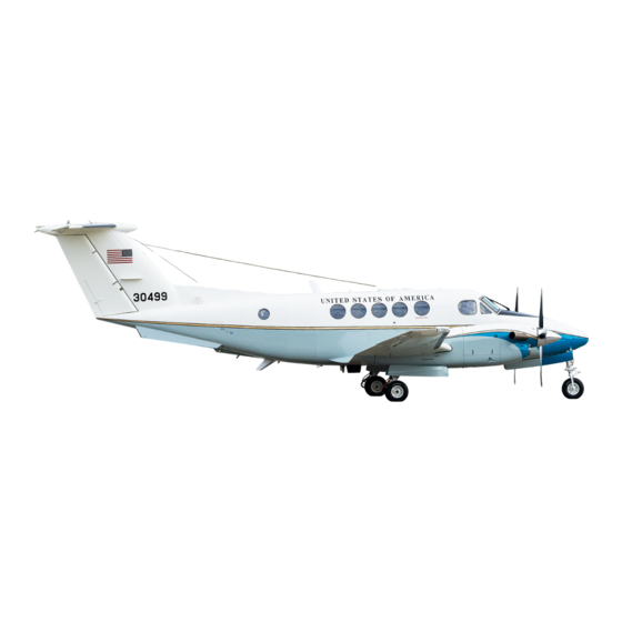
Beechcraft C-12C Operator And Technical Reference Manual

Beechcraft C-12C Operator And Technical Reference Manual

Army c-12c aircraft nsn 1510-01-070-3661, army c-12d aircraft nsn 1510-01-087-9129, army c-12t aircraft nsn 1510-01-470-0220
Table of Contents

Advertisement

TECHNICAL MANUAL
OPERATOR'S MANUAL
FOR
ARMY C-12C AIRCRAFT
NSN 1510-01-070-3661
ARMY C-12D AIRCRAFT
NSN 1510-01-087-9129
ARMY C-12T AIRCRAFT
NSN 1510-01-470-0220
Distribution statement A: Approved for public
release, distribution is unlimited.
*This manual supersedes TM-1-1510-218-10 dated
4 September 2001.
HEADQUARTERS
DEPARTMENT OF THE ARMY
 2&72%(5 200
*TM 1-1510-218-10
WARNING DATA
TABLE OF CONTENTS
INTRODUCTION
DESCRIPTION AND
OPERATION
AVIONICS
MISSION EQUIPMENT
OPERATING LIMITS AND
RESTRICTIONS
WEIGHT/BALANCE AND
LOADING
PERFORMANCE DATA
NORMAL PROCEDURES
EMERGENCY PROCEDURES
REFERENCES
ABBREVIATIONS AND
TERMS
ALPHABETICAL INDEX

Advertisement

Table of Contents
loading

Summary of Contents for Beechcraft C-12C

  • Page 1 *TM 1-1510-218-10 TECHNICAL MANUAL WARNING DATA OPERATOR'S MANUAL TABLE OF CONTENTS ARMY C-12C AIRCRAFT NSN 1510-01-070-3661 INTRODUCTION ARMY C-12D AIRCRAFT NSN 1510-01-087-9129 DESCRIPTION AND OPERATION ARMY C-12T AIRCRAFT AVIONICS NSN 1510-01-470-0220 MISSION EQUIPMENT OPERATING LIMITS AND RESTRICTIONS WEIGHT/BALANCE AND LOADING...
  • Page 3 TM 1-1510-218-10 WARNING PAGE Personnel performing operations, procedures, and practices that are included or implied in this technical manual shall observe the following warnings. Disregard of these warnings and precautionary information can cause serious injury or loss of life. NOISE LEVELS Sound pressure levels in this aircraft during some operating conditions exceed the Surgeon General's hearing conservation criteria, as defined in TB MED 501.
  • Page 4 TM 1-1510-218-10 CARBON MONOXIDE When smoke, suspected carbon monoxide fumes, or symptoms of lack of oxygen (hypoxia) exist, all personnel shall immediately don oxygen masks, and activate the oxygen system. FUEL AND OIL HANDLING Turbine fuels and lubricating oils contain additives that are poisonous and readily absorbed through the skin.
  • Page 5 TM 1-1510-218-10 OPERATION OF AIRCRAFT ON GROUND Engines shall be started and operated only by authorized personnel. Reference AR 95-1. LCCS contractor personnel are authorized IAW the Contract and Statement of Work. Ensure that landing gear control handle is in the DN position. c/(d blank)
  • Page 7 TM 1-1510-218-10 INSERT LATEST CHANGE PAGES. DESTROY SUPERSEDED PAGES. LIST OF EFFECTIVE PAGES NOTE: The portion of the text affected by the changes is indicated by a vertical line in the outer margins of the page. Changes to illustrations are indicated by miniature pointing hands.
  • Page 9: Table Of Contents

    WASHINGTON, DC, 1 OCTOBER 2009 OPERATOR'S MANUAL FOR ARMY C-12C, C-12D, C-12T1, AND C-12T2 AIRCRAFT REPORTING OF ERRORS AND RECOMMENDING IMPROVEMENTS You can help improve this manual. If you find any mistakes or if you know of a way to improve the procedures, please let us know.
  • Page 10 TM 1-1510-218-10 TABLE OF CONTENTS (Continued) Page CHAPTER 3B AVIONICS .........................3B-1 Section I. General ...........................3B-1 Section II. Communications ......................3B-1 Section III. Navigation ........................3B-12 Section IV. Radar and Transponder....................3B-56 CHAPTER 3C AVIONICS T1 T2 ......................3C-1 Section I. General ...........................3C-1 Section II. Communications ......................3C-2 Section III.
  • Page 11 TM 1-1510-218-10 TABLE OF CONTENTS (Continued) Page CHAPTER 8A NORMAL PROCEDURES T2.................. 8A-1 Section I. Mission Planning......................8A-1 Section II. Operating Procedures And Maneuvers ................8A-1 Section III. Instrument Flight ......................8A-20 Section IV. Flight Characteristics ....................8A-20 Section V. Adverse Environmental Conditions................8A-23 Section VI.
  • Page 13: Chapter 1 Introduction

    1-5. APPENDIX B, ABBREVIATIONS AND TERMS. These instructions are for use by the operator. Appendix B is a listing of abbreviations and They apply to the C-12C, C-12D1, C-12D2, C-12T1, terms used throughout the manual. and C-12T2 model aircraft. 1-6. INDEX.
  • Page 14 C-12C C-12D1/D2, C-12T1/T2 Aircraft All C-12T1 and C-12T2 aircraft. Chapter 3A Avionics – C-12C and C-12D1 Aircraft C-12T1 aircraft with serial numbers 85-51262 through 85-51268 and 85-51270 through Chapter 3B Avionics – C-12D2 Aircraft 85-51272 modified with the cockpit and digital engine instrument upgrade.
  • Page 15 TM 1-1510-218-10 1-17. NORMAL PROCEDURES. This manual contains two Normal Procedures chapters entitled as follows. Chapter 8 Normal – C-12C and C-12D1/D2 Aircraft Procedures Chapter 8A Normal – C-12T1/T2 Aircraft Procedures 1-3/(1-4 blank)
  • Page 17: Aircraft And Systems Description And Operation

    Minimum ground turning radius of the aircraft is fasten seat belt, and emergency lighting. shown in Figure 2-4. Table 2-1. Main Differences Between Models ITEM C-12C C-12D C-12T1/T2 Wing span 54 ft. 6 in. 55 ft. 6.5 in.
  • Page 18 TM 1-1510-218-10 1. Radar Antenna 13. ADF No. 1 and No. 2 Loop Antennas (2) 2. Condenser Air Inlet (Right) Air Exhaust (Left) 14. VHF No. 2 and UHF Comm Antenna 3. Free Air Temperature Sensor 15. DME Antenna 4. Emergency Escape Hatch (Right) 16.
  • Page 19 TM 1-1510-218-10 1. Radar Antenna 14. ADF No. 1 and No. 2 Loop Antennas (2) 2. Free Air Temperature Sensor 15. VHF No. 2 and UHF Comm Antenna 3. Emergency Escape Hatch (Right) 16. Marker Beacon Antenna 4. HF Comm Antenna 17.
  • Page 20 TM 1-1510-218-10 1. Radar Antenna 17. Radio Altimeter Antennas 2. Free Air Temperature Sensor 18. ADF No. 1 and No. 2 Loop Antennas (2) 3. Top TCAS Antenna 19. VHF No. 2 and UHF Comm Antenna 4. Emergency Escape Hatch (Right) 20.
  • Page 21 TM 1-1510-218-10 Figure 2-2. Typical General Interior Arrangement...
  • Page 22 TM 1-1510-218-10 Figure 2-3. Principal Dimensions (Sheet 1 of 2)
  • Page 23 TM 1-1510-218-10 Figure 2-3. Principal Dimensions (Sheet 2 of 2)
  • Page 24 TM 1-1510-218-10 RADIUS FOR INSIDE GEAR………………………….. .4 FEET RADIUS FOR NOSE WHEEL………………………… 19 FEET 6 INCHES RADIUS FOR OUTSIDE GEAR………………………. 21 FEET 1 INCH RADIUS FOR WING TIP C…….…...…………….…... 39 FEET 10 INCHES RADIUS FOR WING TIP …...…………..……..… 40 FEET 4 INCHES TURNING RADII ARE PREDICATED ON THE USE OF PARTIAL BRAKING ACTION AND DIFFERENTIAL POWER.
  • Page 25 TM 1-1510-218-10 2-5. MAXIMUM WEIGHTS. 1 The aft CG limit above 12,500 pounds is 196.4 ARM inches. a. Operations At or Below 12,500 Pounds. 2 The forward CG limit at 13,500 pounds is 188.3 ARM inches. Intermediate values to (1) Takeoff. Maximum Gross Takeoff Weight 12,500 vary linearly to 185.0 ARM inches.
  • Page 26 TM 1-1510-218-10 be a minimum of 60 minutes in duration unless connected to the landing gear. The nose wheel restricted by Air Traffic Control, turbulence, other steering mechanism is automatically centered and the weather conditions, or emergencies. rudder pedals relieved of the steering load when the landing gear is retracted.
  • Page 27 TM 1-1510-218-10 NOTE The danger areas include the resultant increase in velocity and significant reduction in temperature due to propeller wake. EXHAUST DANGER AREA (GROUND LEVEL) EXHAUST DANGER AREA (MAXIMUM POWER) PROPELLER DANGER AREA Figure 2-5. Exhaust and Propeller Danger Areas 2-11...
  • Page 28 TM 1-1510-218-10 1. PILOT AIR Inlet Control 12. Landing Gear Handle Down Lock Release 2. DEFROST AIR Control 13. Recognition Lights Switch 3. PILOT’S STATIC AIR SOURCE Control 14. Manual Engine ICE VANE Controls 4. Flap Position Indicator 15. ANNUNCIATOR TEST Switch 5.
  • Page 29 TM 1-1510-218-10 e. Landing Gear Warning Horn. When either Manual landing gear extension is provided power lever is retarded below approximate 79% N , or through a manually powered system as a backup to when the landing gear is not down and locked; or if the the electrically operated system.
  • Page 30 TM 1-1510-218-10 Power Levers (2) Propeller Levers (2) Condition Levers (2) FRICTION LOCK Knobs WING FLAP Switch RUDDER TAB Control and Position Indicator ICS #2 Control Panel COMM 1 Control Panel COMM 2 Control Panel NAV 1/NAV 2 Control Panel Blank Panel ADF Control Panel UHF Control Panel...
  • Page 31 TM 1-1510-218-10 2-8. LANDING GEAR SYSTEM D2 T charged with nitrogen to 800 ± 50 psi. Gear doors are opened and closed through a mechanical linkage retractable tricycle landing gear connected to the landing gear. The nose wheel steering mechanism is automatically centered and the electrically controlled and hydraulically actuated.
  • Page 32 TM 1-1510-218-10 1. FLIGHT Hour Indicator 14. GEAR DOWN Indicator Lights (3) 2. CABIN TEMP Indicator 15. PARKING BRAKE Control 3. PILOT AIR Inlet Control 16. Manual Engine Ice Vane Control 4. DEFROST AIR Control 17. ANNUNCIATOR TEST Switch 5. PILOT’S STATIC AIR SOURCE Control 18.
  • Page 33 TM 1-1510-218-10 1. FLIGHT Hour indicator 11. TAXI LIGHT Switch 2. Push Button Switch 12. RECOG (Recognition) Lights Switch 3. ITT Temperature Circuit Breaker #1 13. HDL LT TEST Switch (Light Inside Landing 4. ITT Temperature Circuit Breaker #2 Gear Control Handle) 5.
  • Page 34 TM 1-1510-218-10 1. Battery Temperature Test Switch 17. HYD FLUID SENSOR TEST Switch Indicator 18. Landing Gear WARNING HORN SILENCE 2. ITT Temperature Circuit Breaker #2 Switch 3. ITT Temperature Circuit Breaker #1 19. Engine Ice Vane Manual Control 4. PROP RPM Circuit Breaker #1 20.
  • Page 35 TM 1-1510-218-10 e. Landing Gear Warning System . The power levers are advanced above 81% N and/or landing gear warning system is provided to warn the airspeed increases above 140 KIAS. pilot that the landing gear is not down and locked during specific flight regimes.
  • Page 36 LDG GEAR CONTR handle is in the DN position. Remove the extension lever from C-12C aircraft are equipped with dual the securing clip and pump the lever up and down until 18 x 5.5, 8 ply rating tubeless rim inflation tires on...
  • Page 37 TM 1-1510-218-10 Figure 2-9. Control Pedestal (Sheet 1 of 3) 2-21...
  • Page 38 TM 1-1510-218-10 Figure 2-9. Control Pedestal (Sheet 2 of 3) 2-22...
  • Page 39 TM 1-1510-218-10 Figure 2-9. Control Pedestal (Sheet 3 of 3) 2-23...
  • Page 40 TM 1-1510-218-10 1. Free Air Temperature Gauge 2. Oxygen Mask 3. Storm Window Lock 4. Microphone 5. Headset 6. Sun Visor 7. Oxygen Control Panel 8. Overhead Circuit Breaker and Control Panel 9. Fuel Management Panel 10. Windshield Wipers 11. Magnetic Compass 12.
  • Page 41 TM 1-1510-218-10 2-10. WHEEL BRAKE SYSTEM. a. Cabin Door . A swing-down door, hinged at the bottom, provides positive cabin security for flight and a convenient stairway for entry and exit, The main landing wheels are equipped with Figure 2-11. Two of the three steps are movable and multiple-disc hydraulic brakes actuated by master automatically fold flat against the door in the closed cylinders attached to the rudder pedals at the pilot's...
  • Page 42 TM 1-1510-218-10 Figure 2-11. Cabin Door and Cabin Emergency Hatch b. Cabin Door A swing-down door, the cargo door. A button adjacent to the door handle hinged at the bottom, provides a stairway for normal must be pressed before the handle can be rotated to and emergency entry and exit.
  • Page 43 TM 1-1510-218-10 Figure 2-12. Cabin Door and Cabin Emergency Hatch 2-27...
  • Page 44 TM 1-1510-218-10 the handle to the OPEN position. Latch handle in WARNING place. Secure the access door. Attach one end of the door support assembly to the cargo door ball stud on The cargo door is a structural panel and the forward side of the door.
  • Page 45 TM 1-1510-218-10 hatch is being removed. On reinstalling the hatch, the cabin window has a vertical sliding curtain to regulate electrical disconnect should be reconnected before light through the window. moving the hatch into the closed position. 2-15. SEATS. 2-13. CABIN DOOR CAUTION LIGHT. a.
  • Page 46 TM 1-1510-218-10 1. Adjustable Headrest 5. Seat Fore Adjustment (Pilot) 2. Seat Belt/Shoulder Harness Buckle Height Adjustment (Copilot) 3. Moveable Armrest 6. Expandable Map Pocket 4. Seat Height Adjustment (Pilot) Fore and Aft Adjustment (Copilot) Figure 2-13. Pilot’s and Copilot’s Seats 2-30...
  • Page 47: Emergency Equipment

    TM 1-1510-218-10 Section II. EMERGENCY EQUIPMENT 2-16. DESCRIPTION. mounted beneath the aft left seat. They are of the Br gas type. The extinguisher is charged to a pressure of 150 to 170 psi, and emits a forceful The equipment covered in this section includes stream.
  • Page 48 TM 1-1510-218-10 1. Primary Prop Governor 15. Air Conditioner Compressor Drive Belt (#2 2. Torque Pressure Transmitter Engine Only) 3. Torque Pressure Switch 16. Fire Detector 4. Torque Pressure Manifold 17. Air Conditioner Compressor (#2 Engine 5. Exhaust Duct Only) 6.
  • Page 49 TM 1-1510-218-10 26. Fuel Control Unit 39. Chip Detector 27. Fuel Control Unit Control Rod 40. Oil Pressure Tube 28. Starter Generator Leads 41. Fire Extinguisher Line 29. Engine Driven Fuel Pump 42. Ignition Exciter Plug 30. Power Control Lever 43.
  • Page 50 TM 1-1510-218-10 2-24. FOREIGN OBJECT DAMAGE CONTROL. (3) In the non-ice protection mode, the vane and by-pass door are retracted out of the air stream by The engine has an integral air inlet screen placing the ice vane switches in the RETRACT position.
  • Page 53 TM 1-1510-218-10 The basic engine fuel system consists of an of its engine-mounted fuel control unit. From LO IDLE engine driven fuel pump, a fuel control unit, a dual fuel to HIGH IDLE, they control the governors of the fuel manifold, 14 fuel nozzles, and a fuel purge system.
  • Page 58 TM 1-1510-218-10 (2) During ground test of the engine fire cable increases, the gases within the tube begin to detection system, an erroneous indication of system expand. When the pressure from the expanding fault may be encountered if an engine cowling is not gases reaches a preset point, the contacts of the closed properly, or if the aircraft is headed toward a responder alarm switch close, activating the respective...
  • Page 63 TM 1-1510-218-10 b. The fire control handles used to arm the 2-33. OIL SUPPLY SYSTEM. extinguisher system are centrally located on the pilot's instrument panel immediately below the glareshield. a. The engine oil tank is integrated with the air- These controls receive power from the hot battery bus. inlet casting located forward of the accessory gearbox.
  • Page 64 TM 1-1510-218-10 2-35. ENGINE IGNITION SYSTEM. switch is protected by a corresponding 5-ampere circuit breaker, placarded START CONTR #1 or START CONTR #2, located on the overhead circuit a. The basic ignition system consists of a solid- breaker panel, Figure 2-16. state ignition exciter unit, two igniter plugs, two shielded ignition cables, pilot-controlled IGNITION AND ENGINE START switches, and the ENG AUTO...
  • Page 65 TM 1-1510-218-10 respective propeller reduction gear case. The indicator is equipped with a Built In Test Torquemeters are protected by individual 0.5 ampere (BIT) display that will display all active LCD segments circuit breakers, placarded TORQUEMETER #1 or for three seconds on power up. If the BIT test detects TORQUEMETER #2, on the overhead circuit breaker a failed ROM or RAM, the BIT indicator will have a panel.
  • Page 66 TM 1-1510-218-10 NOTE flashing shall cease and digital torque display shall be prefixed with an "E" when the time/torque combination Pressing the EXCEEDENCE ERASE switch is exceeded and the indicator begins recording an for 0.2 seconds or longer will cause all exceedance.
  • Page 67 TM 1-1510-218-10 When displaying exceedence N values the actual NOTE measured value, not "----", shall be displayed, up to Pressing the EXCEEDENCE ERASE switch 199.0% RPM. for 0.2 seconds or longer will cause all events to be erased from non-volatile The indicator shall perform BIT on the LCD memory.
  • Page 68 TM 1-1510-218-10 indicator shall display "0" on both the digital and bar (3) The Display & Key Recorder. graph display. Display and Key Recorder is a cabin mounted display that houses both the key recorder equipment and display interface. The Fuel Flow Indicators are protected by 0.5- ampere circuit breakers, placarded FUEL FLOW #1 and #2, located on the overhead circuit breaker panel.
  • Page 70 TM 1-1510-218-10 or, as backup, the standby fuel pump. The quantity of CAUTION fuel for the tanks is detailed in Table 2-3. Engine operation using only the engine- b. Engine Driven Boost Pumps. A gear-driven driven primary (high-pressure) fuel pump boost pump mounted on each engine supplies fuel, without standby fuel pump or engine- under pressure, from the nacelle tank to the inlet of the...
  • Page 71: Fuel System

    TM 1-1510-218-10 pounds. Refer to Section XII for fuel capacities and CAUTION weights. The system is compensated for fuel density changes due to temperature excursions. In addition to In turbulence or during maneuvers, the NO the fuel gauges, yellow #1 or #2 NAC LOW lights on FUEL XFR light may momentarily illuminate the caution/advisory annunciator panel illuminate when after the auxiliary fuel has completed...
  • Page 72 TM 1-1510-218-10 1. Standby Fuel Pump Switch (#1 Engine) Override 2. Fuel Quantity Indicator (#1 Engine) 3. Fuel Quantity Gauging System Control Switch 4. Fuel Quantity Indicator (#2 Engine) 5. Standby Fuel Pump Switch (#2 Engine) 6. Auxiliary Fuel Transfer Pump Override Switch (#2 Engine) 7.
  • Page 73 TM 1-1510-218-10 NOTE The fuel system incorporates a fuel line shutoff valve on each engine firewall. The firewall shutoff Both switches shall during valves close automatically when the fire extinguisher T crossfeed operation. handles on the instrument panel are pulled out. The firewall shutoff valves receive electrical power from the (4) Fuel Transfer Control Switches.
  • Page 74 TM 1-1510-218-10 entrance door, hold a fuel-proof container under the the wing and contains a heating element. The vent ends, and drain about a pint of fuel out of each line. line at the nacelle contains an inline flame arrester. i.
  • Page 75 TM 1-1510-218-10 Figure 2-20. Gravity Feed Fuel Flow 2-59...
  • Page 76 TM 1-1510-218-10 Figure 2-21. Crossfeed Fuel Flow 2-60...
  • Page 77: Flight Controls

    TM 1-1510-218-10 2-43. FERRY FUEL SYSTEM. noted above, opens a path for the fuel to the main aircraft fuel tanks, which have NOTE only ambient pressure over the fuel. Cabin pressure will force the fuel out of the ferry The ferry fuel system is installed in the fuel tanks into the aircraft main fuel tanks, aircraft for the specified ferry flight only.
  • Page 78 TM 1-1510-218-10 operated by manually actuating either the pilot's or powered digital clock/timers. Each control wheel copilot's control wheel. Electric switches are installed incorporates a bracket to allow mounting a chart in the outboard grip of each wheel to operate the holder, Figure 2-22, Sheet 4.
  • Page 79 TM 1-1510-218-10 1. Microphone Switch 2. Autopilot/Yaw Damp Disconnect 3. Electric Trim Control Switches 4. Pitch Sync and Control Wheel Steering Switch 5. Transponder Indent Switch 6. Map Light Switch 7. 8-Day Clock 8. Clock Light Switch Figure 2-22. Control Wheels C D1 (Sheet 1 of 4) 2-63...
  • Page 80 TM 1-1510-218-10 1. Microphone Switch 6. Map Light Switch 2. Autopilot/Yaw Damp Disconnect Switch 7. 8-Day Clock 3. Electric Trim Control Switches 8. Clock Light Switch 4. Touch Control Steering Switch 5. Line Advance Switch COPILOT 1. Microphone Switch 6. Line Advance Switch 2.
  • Page 81 TM 1-1510-218-10 1. Microphone Switch 2. Autopilot/Yaw Damp Disconnect Switch 3. Electric Trim Control Switches 4. Go Around Switch 5. Touch Control Steering Switch 6. Line Advance Switch 7. Clock 8. Map Light Switch 9. Clock Light Switch Figure 2-22. Control Wheels (Sheet 3 of 4) 2-65...
  • Page 82 TM 1-1510-218-10 1. Microphone Switch 2. Autopilot/Yaw Damp Disconnect Switch 3. Electric Trim Control Switches 4. Go Around Switch 5. Touch Control Steering Switch 6. Line Advance Switch 7. Clock 8. Map Light Switch 9. Quick Tune Switch Figure 2-22. Control Wheels (Sheet 4 of 4) 2-66...
  • Page 83 TM 1-1510-218-10 2-46. RUDDER SYSTEM. NOTE Condition levers must be in LOW IDLE a. Rudder Pedals. Aircraft directional control position to perform rudder boost check. and nose wheel steering is accomplished by actuation of the rudder pedals from either pilot's or copilot's (2) The system is controlled by a switch station, Figure 2-10.
  • Page 84 TM 1-1510-218-10 Figure 2-23. Control Lock Installation Typical 2-48. TRIM TABS. thumb switch is moved forward for trimming nose down, aft for nose up, and when released returns to the center (off) position. Any activation of the trim Trim tabs are provided for all control surfaces. system through the copilot's trim switch can be These tabs...
  • Page 85: Propellers

    TM 1-1510-218-10 d. Rudder Trim Tab Control. The rudder trim handle on the control pedestal, Figure 2-7 and 2-9. tab control knob, placarded RUDDER TAB / LEFT / The handle of this switch is placarded FLAP and RIGHT, is on the control pedestal, and controls switch positions placarded...
  • Page 86 TM 1-1510-218-10 panel indicate a fully armed system. The annunciator 2-52. PROPELLER GOVERNORS. panel lights green placarded AUTOFEATHER (left eng) and 2 AUTOFEATHER Two governors, a constant speed (primary) (right eng). The system will remain inoperative as long governor, and an overspeed governor, control the as either power levers is retarded below 90% N propeller RPM.
  • Page 87 TM 1-1510-218-10 propeller is feathered while the synchrophaser is on, level. The RPM of one engine will follow the changes the synchrophaser has a limited range of control from in RPM of the other engine over a predetermined the manual governor setting. Normal governor range (approximately 20-RPM).
  • Page 88 TM 1-1510-218-10 active LCD segments for three seconds on power up. CAUTION If the ROM or RAM fails BIT the indicator display will be blank. If the input signal fails BIT the indicator will Propeller reversing unimproved prefix the digital display with "F". surfaces should be accomplished carefully to prevent propeller erosion from reversed BIT failures are not stored in EEPROM.
  • Page 89: Utility Systems

    TM 1-1510-218-10 prefixed to the digital display will be removed. NOTE event data is still available for playback until the data is Pressing the EXCEEDENCE ERASE switch erased. The display will be prefixed with an "E" again for 0.2 seconds or longer will cause all on the next power up cycle if the old data has not been events to be erased from non-volatile erased or if another event is recorded.
  • Page 90 TM 1-1510-218-10 (4) Either engine is capable of providing controls the manual override relays. When the switch sufficient bleed air for all requirements of the surface is in the OUTER position, the automatic timer is deicer system. Check valves in the bleed air and overridden and power is supplied to the outer heating vacuum lines prevent backflow through the system elements of both propellers simultaneously.
  • Page 91 TM 1-1510-218-10 panel. The auto mode circuit is protected by a circuit placarded STALL WARN / ON. The level of heat is breaker located on the dc power distribution panel. minimal for ground operation but is automatically increased for flight operation through the landing gear safety switch.
  • Page 92 TM 1-1510-218-10 gear up-lock switch. When the system is activated, circuit breaker panel. Each fuel governing line is the BRAKE DEICE ON light should be monitored and protected against ice by an electrically heated jacket. the control switch selected off after the light A 7.5-ampere circuit breaker located on the overhead extinguishes otherwise, on the next gear extension the circuit breaker panel, placarded FUEL CONTR HEAT /...
  • Page 93 TM 1-1510-218-10 inadvertent switching to the HI position during system PRESS DUMP / PRESS / TEST, is provided to control shutdown. pressurization. The switch is spring loaded to the PRESS position. In the DUMP position, the safety valve will be opened and the cabin will be NOTE depressurized to the aircraft altitude.
  • Page 94 TM 1-1510-218-10 h. Cabin Rate-Of-Climb Indicator D2 T . An m. Drain. A drain in the outflow valve static indicator, placarded CABIN CLIMB, is installed just control line is provided for removal of accumulated ahead of the control quadrant. It is calibrated in moisture.
  • Page 95 TM 1-1510-218-10 aft toilet compartment outlets. Adjacent to the system d. Oxygen Duration. The oxygen duration control knob is another push-pull knob, placarded depends upon the amount of oxygen available and the CABIN / PULL ON / PASS READY. This actuates the demand.
  • Page 96 TM 1-1510-218-10 life raft, toilet etc. A placard inside the door reads (c) Emergency (EMERG) Mode. Turning NOTE: CREW SYS MUST BE ON as a reminder that the EMERG knob, located on the bottom of the the PULL ON SYS READY knob in the cockpit must regulator, places the mask in the emergency mode.
  • Page 97 TM 1-1510-218-10 Figure 2-24. Oxygen System Servicing Pressure Chart 2-81...
  • Page 98 TM 1-1510-218-10 Table 2-5. Oxygen Flow Planning Rates vs Altitude NOTE All flows in LPM per mask at NTPD If average climb or descent flows are desired, add the values between altitudes and divide by the number of values used. This method is preferred over averaging the extremes as some flow characteristics vary in such a way as to yield an incorrect answer.
  • Page 99 TM 1-1510-218-10 Table 2-6. Oxygen Duration in Minutes for 49 Cubic Foot System (Continued) CABIN CREW MASK TOTAL FLOW DURATION IN PRESSURE CONDITION LPM-NTPD MINUTES (1) ALTITUDE NOTE When operating with a 100% cylinder capacity, read the duration in minutes directly from the table.
  • Page 100 TM 1-1510-218-10 Table 2-6. Oxygen Duration in Minutes for 49 Cubic Foot System (Continued) CABIN CREW MASK TOTAL FLOW DURATION IN PRESSURE CONDITION LPM-NTPD MINUTES (1) ALTITUDE 31,000 100% 23.2 52.7 20,000 100% 30.0 40.7 20,000 NORMAL 22.0 55.5 TWO MAN CREW 15,000 100% 33.8...
  • Page 101 TM 1-1510-218-10 Table 2-6. Oxygen Duration in Minutes for 49 Cubic Foot System (Continued) CABIN CREW MASK TOTAL FLOW DURATION IN PRESSURE CONDITION LPM-NTPD MINUTES (1) ALTITUDE 31,000 100% 41.7 29.3 20,000 100% 48.5 25.2 20,000 NORMAL 40.5 30.2 TWO MAN CREW 15,000 100% 52.3...
  • Page 102 TM 1-1510-218-10 Figure 2-25. Oxygen System (Sheet 1 of 2) 2-86...
  • Page 103 TM 1-1510-218-10 Figure 2-25. Oxygen System (Sheet 2 of 2) 2-87...
  • Page 104 TM 1-1510-218-10 2-71. WINDSHIELD WIPERS. from the aft side of the doorway to the back of the pressurized compartment. A partition wall, with lockable internal sliding doors at the aisle, separates a. Description. Two electrically operated the passenger area from the toilet area. A mirror is windshield wipers are provided for use at takeoff, mounted on the right forward partition and a cruise, and landing speed.
  • Page 105 TM 1-1510-218-10 d. Cargo Configuration. The cabin area can distribution panel under the floor ahead of the main be quickly converted for combination passenger/cargo spar. or all cargo use by removing the seats and partial partition. Cargo containers are secured with tiedown b.
  • Page 106 TM 1-1510-218-10 Figure 2-26. Environmental System 2-90...
  • Page 107 TM 1-1510-218-10 2-78. AIR CONDITIONING. breaker for this blower is located on the dc distribution panel in the lower equipment bay. a. Cabin air conditioning is provided by a refrigerant gas vapor cycle refrigeration system d. When operating under very hot, humid consisting belt driven...
  • Page 108 TM 1-1510-218-10 (2) If the cockpit is too hot: mode. A temperature sensing unit in the cabin, in conjunction with the control setting, initiates a heat or cool command to the temperature controller for 1. CABIN AIR knob – As required. desired cockpit and cabin environment.
  • Page 109: Electrical Power Supply And Distribution System

    TM 1-1510-218-10 OFF position. In the OFF position, the blower will not AFT VENT BLOWER switch is placed in the AUTO operate. position with the landing gear extended. The blower will automatically shut off when the landing gear is retracted. The blower operates continuously when the (3) The aft vent blower is controlled by a switch is placed in the ON position and there is a cool switch, placarded AFT VENT BLOWER / OFF / AUTO...
  • Page 110 TM 1-1510-218-10 Figure 2-27. DC Electrical System Schematic C D1 2-94...
  • Page 111 TM 1-1510-218-10 Table 2-7. DC Electrical System C D1 (Continued) #1 AVIONICS BUS HF RCVR PILOT AUDIO INTPH #1 VHF AP PWR #1 VOR TRANSPONDER PILOTS ALT ENCD #1 ADF VOICE ADVSR #1 RMI AFCS DIRECT RADIO ALTM #2 AVIONICS BUS #2 VHF COPILOT AUDIO SERVO DC...
  • Page 112 TM 1-1510-218-10 Table 2-7. DC Electrical System C D1 (Continued) ENGINE #1 START CONTR #1 ICE VANE CONTR #1 IGNITOR CONTR PROP SYNC #4 DUAL FED BUS WEATHER STALL WARN RIGHT PROP ANTI-ICE PROP ANTI-ICE CONTR BRAKE DEICE RIGHT FUEL VENT HEAT RIGHT FUEL CONTR HEAT RIGHT PITOT HEAT FUEL...
  • Page 113 TM 1-1510-218-10 Table 2-7. DC Electrical System C D1 (Continued) HOT BATTERY BUS #1 FIREWALL SHUTOFF VALVE AFT BAGGAGE LIGHTS #2 ENGINE FIRE EXTINGUISHER #1 ENGINE FIRE EXTINGUISHER SPAR & THRESHOLD LIGHTS #2 STANDBY FUEL PUMP #1 STANDBY FUEL PUMP SHADIN ETMS DOOR STEP &...
  • Page 114 TM 1-1510-218-10 Figure 2-28. DC Electrical System Schematic D2 T1 (Sheet 1 of 2) 2-98...
  • Page 115 TM 1-1510-218-10 Figure 2-28. DC Electrical System Schematic (Sheet 2 of 2) 2-99...
  • Page 116 TM 1-1510-218-10 Table 2-8. DC Electrical System (Continued) #1 AVIONICS BUS HF RCVR PILOT AUDIO #1 AFCS #1 VHF AIR DATA ENCODER AP PWR #1 NAV TRANSPONDER TACAN #1 ADF #2 RMI PAGING #2 AVIONICS BUS #2 VHF COPILOT AUDIO GRAPHIC DISPLAY #2 NAV RADIO ALTIMETER...
  • Page 117 TM 1-1510-218-10 Table 2-8. DC Electrical System (Continued) ENGINE #1 START CONTR #1 ICE VANE CONTR #1 IGNITOR CONTR PROP SYNC #4 DUAL FED BUS WEATHER STALL WARN RIGHT PROP ANTI-ICE PROP ANTI-ICE CONTR BRAKE DEICE RIGHT FUEL VENT HEAT RIGHT FUEL CONTR HEAT RIGHT PITOT HEAT FUEL...
  • Page 118 TM 1-1510-218-10 Table 2-9. DC Electrical System (Continued) #1 AVIONICS BUS FMS #1 HF RCVR AIR DATA ENCODER #1 AFCS #1 VHF TRANSPONDER AP PWR #1 NAV TACAN #1 ADF PAGING PILOT HSI MFD #2 RMI TCAS PROCESSOR CONTROL DISPLAY UNIT PILOT DCU PILOT MFD CONTROL PANEL MODE S ALTIMETER ENCODER...
  • Page 119 TM 1-1510-218-10 Table 2-9. DC Electrical System (Continued) WEATHER WSHLD WIPER LEFT PROP ANTI-ICE PROP ANTI-ICE AUTO SURF DEICE LEFT FUEL VENT HEAT LEFT FUEL CONTR HEAT FUEL CROSSFEED #1 FIREWALL VALVE #1 PRESS WARN ENGINE #1 START CONTR #1 ICE VANE CONTR #1 IGNITOR CONTR PROP SYNC #4 DUAL FED BUS...
  • Page 120 TM 1-1510-218-10 Table 2-9. DC Electrical System (Continued) AVIONICS AVIONICS MASTER CONTR COMPASS SWITCHING TRANSPONDER EMERG MODE AVIONICS ANNUNCIATOR HOT BATTERY BUS #1 FIREWALL SHUTOFF VALVE #2 FIREWALL SHUTOFF VALVE AFT BAGGAGE LIGHTS #1 ENGINE FIRE EXTINGUISHER #2 ENGINE FIRE EXTINGUISHER SPAR &...
  • Page 121 TM 1-1510-218-10 Table 2-10. DC Electrical System (Continued) #2 DUAL FED BUS WARNING ANN PWR FIRE DETR RIGHT BLEED AIR WARN #2 CHIP DETR LANDING GEAR WARN FUEL #2 QTY IND #2 STANDBY PUMP #2 AUXILIARY TRANSFER #2 QTY WARN #2 EADI ENGINE #2 OIL TEMP...
  • Page 122 TM 1-1510-218-10 Table 2-10. DC Electrical System (Continued) INST INDIRECT RECOG LANDING LIGHTS RADIO PANEL ENVIRONMENTAL TEMP CONTR LEFT BLEED AIR CONTR AIR COND CONTR ELECTRICAL #1 GEN RESET #6 DUAL FED BUS FLIGHT RUDDER BOOST FLAP CONTR LIGHTS EMERG LIGHTS FLT INST OVHD LIGHTS &...
  • Page 123 TM 1-1510-218-10 GENERATOR , are located on the overhead that the battery is approaching a full charge. The time control panel under the MASTER SWITCH. interval will increase if the battery has a low state of toggle switches control electrical power from the charge, the battery temperature is very low, or if the designated generator to paralleling circuits and the bus battery has previously been discharged at a very low...
  • Page 124 TM 1-1510-218-10 or voltage is insufficient to keep it connected to the mounted on the dc power distribution panel mounted power distribution system. beneath the floor. Aircraft equipment operating from single-phase ac include the following: autopilot navigation receivers, the tuning portion of the ADF CAUTION receiver, gyro...
  • Page 125 TM 1-1510-218-10 f. Volt-Frequency Meters Two digital frequency (Hz) are continuously displayed. Normal display volt-frequency meters are mounted in the output of the inverters will be indicated by 115 Vac and overhead control panel to provide a monitoring 400 Hz on the meters. capability for both 115 Vac buses.
  • Page 126 TM 1-1510-218-10 Figure 2-29. AC Electrical System Schematic Diagram (Sheet 2 of 3) 2-110...
  • Page 127 TM 1-1510-218-10 Figure 2-29. AC Electrical System Schematic Diagram (Sheet 3 of 3) 2-111...
  • Page 128: Lighting

    TM 1-1510-218-10 Section X. LIGHTING 2-85. EXTERIOR LIGHTING. e. Ice Lights. The ice lights are protected by a 5-ampere circuit breaker, placarded ICE, on the overhead circuit breaker panel. The lights are a. Description. Exterior lighting consists of a controlled by a switch, placarded ICE ON, on the navigation light on the aft top of the vertical stabilizer, one navigation light on each wing tip, two strobe overhead control panel.
  • Page 129 TM 1-1510-218-10 1. Landing/Taxi Lights 2. Upper Strobe Beacon 3. Tail Navigation Light 4. Emergency Exit Light 5. Lower Strobe Beacon 6. Wing Navigation Lights 7. Recognition Lights 8. Ice Lights Figure 2-30. Exterior Lighting – Typical 2-113...
  • Page 130 TM 1-1510-218-10 b. Cockpit Lighting. (6) Overhead Panel Lights C D T1 . Lamps on the overhead circuit breaker panel, control panel, and fuel management panel are protected by a (1) Flight Instrument Lights. Each individual 7.5-ampere circuit breaker, placarded LIGHTS OVHD, flight instrument contains...
  • Page 131 TM 1-1510-218-10 breaker, placarded LIGHTS FLT INST, on the (4) Reading Lights. Reading lights are overhead circuit breaker panel. Control is provided by installed in the upholstery adjacent to each seat a push-button switch adjacent to the gauge. position. The circuit is protected by a 10-ampere intensity control is provided.
  • Page 132: Flight Instruments

    TM 1-1510-218-10 Section XI. FLIGHT INSTRUMENTS 2-88. PITOT AND STATIC SYSTEM. 2-89. TURN-AND-SLIP INDICATORS C D1 NOTE Turn and slip indicators are installed separately on the pilot and copilot sides of the instrument panel, Instrument panels for each model aircraft Figure 2-17, Sheet 1.
  • Page 133 TM 1-1510-218-10 Figure 2-31. Pitot and Static System 2-117...
  • Page 134 TM 1-1510-218-10 2-93. PILOT’S ALTIMETER C D1 COPILOT ALTM, located on the overhead circuit breaker panel. The altimeter is located on the upper left side of the instrument panel. The altimeter is a self-contained 2-96. VERTICAL VELOCITY INDICATORS. unit, which consists of a precision pressure altimeter combined with an altitude encoder.
  • Page 135 TM 1-1510-218-10 the individual warning annunciator lights. Table 2-12 (3) The MASTER PANEL LIGHTS switch is provides a list of causes for illumination of the off. individual caution/advisory annunciator lights. frontal view, both panels present rows of small opaque (4) The MASTER PANEL LIGHTS switch is rectangular indicator lights.
  • Page 136 TM 1-1510-218-10 Table 2-11. C-12 Warning Annunciator Panels (Continued) NOMENCLATURE COLOR CAUSE FOR ILLUMINATION AIRCRAFT EFFECTIVITY Left bleed air warning line has melted or failed, indicating L BL AIR FAIL possible loss of #2 engine bleed air. R BL AIR FAIL Right bleed air warning line has melted or failed, indicating possible loss of #2 engine bleed air.
  • Page 137 TM 1-1510-218-10 Table 2-12. C-12 Caution/Advisory Annunciator Panels (Continued) NOMENCLATURE COLOR CAUSE FOR ILLUMINATION AIRCRAFT EFFECTIVITY #1 NAC LOW Yellow #1 engine has 20 minutes or 30 minutes D T1 fuel remaining at sea level, normal cruise power consumption rate. CABIN DOOR Yellow Cabin/cargo door open or not secure.
  • Page 138 TM 1-1510-218-10 Table 2-12. C-12 Caution/Advisory Annunciator Panels (Continued) NOMENCLATURE COLOR CAUSE FOR ILLUMINATION AIRCRAFT EFFECTIVITY #1 DC GEN ANVIS #1 engine generator off the line. Green #1 INVERTER ANVIS #1 inverter inoperative. Green ANVIS Auxiliary fuel tank on side of #1 engine not transferring #1 NO FUEL XFR Green fuel into nacelle tank.
  • Page 139 TM 1-1510-218-10 Table 2-12. C-12 Caution/Advisory Annunciator Panels (Continued) NOMENCLATURE COLOR CAUSE FOR ILLUMINATION AIRCRAFT EFFECTIVITY #1 IGN ON ANVIS #1 engine ignition/start switch on or #1 engine auto Green ignition switch armed and engine torque below 20%. L BL AIR OFF ANVIS Left environmental bleed air valve closed.
  • Page 140: Servicing, Parking, And Mooring

    TM 1-1510-218-10 d. Master Warning Light D2 T MASTER of the glareshield adjacent to the MASTER WARNING WARNING lights (red) are provided for both the pilot lights, Figure 2-17. Whenever a caution light and copilot. They are located on the left and right side illuminates, the MASTER CAUTION will illuminate and of the glareshield adjacent to the MASTER CAUTION will stay illuminated until the condition is corrected...
  • Page 141 TM 1-1510-218-10 3. Carefully remove snow, water, and ice CAUTION from the aircraft fuel filler cap area before removing the fuel filler cap. Remove only Do not fill the auxiliary fuel tanks unless one aircraft tank filler cap at any one time, outboard main tanks are full.
  • Page 142 TM 1-1510-218-10 1. Outboard Fuel Sump Drain 10. Ram Scoop Vent (Both Sides) 2. Bleed Air Heat Exchanger Exhaust 11. Engine Oil Vent (Both Sides) 3. Bleed Air Heat Exchanger Intake 12. Transfer Pump Filter Drain 4. Battery Ram Air Vent 13.
  • Page 143 TM 1-1510-218-10 Table 2-13. Approved Fuels (Continued) PRIMARY OR SOURCE STANDARD FUEL ALTERNATE FUEL US Military Fuel JP-8 (MIL-T-5624) JP-5 (MIL-T-5624) NATO Code No. F-40 (Wide Cut Type) F-44 (High Flash Type) COMMERCIAL FUEL JET B JET A JET A-1 (ASTM-D-1655) NATO F-34 American Oil Co.
  • Page 144 TM 1-1510-218-10 NOTE Anti-icing and Biocidal Additive for Commercial Turbine Engine Fuel – The fuel system icing inhibitor shall conform to MIL-I-27686. The additive provides anti-icing protection and also functions as a biocide to kill microbial growths in aircraft fuel systems. Icing inhibitor conforming to MIL-I-27686 (PRIST) shall be added to commercial fuel, not containing an icing inhibitor, during refueling operations, regardless of ambient temperatures.
  • Page 145 TM 1-1510-218-10 usually occurs during cross-country flights where CAUTION aircraft using NATO F-44 (JP-5) are refueled with NATO F-40 (JP-8) or Commercial ASTM Type B fuels. Ensure that oil filler cap is correctly Whenever this condition occurs, the engine operating installed and securely locked to prevent characteristics may change in that lower operating loss of oil and possible engine failure.
  • Page 146 TM 1-1510-218-10 1. Air Conditioning Compressor 8. Fuel Filler Caps (Typical Left and Right) 2. External Power Receptacle 9. Landing Gear Tires 3. Hand Fire Extinguisher 10. Engine Fire Extinguisher 4. Battery, 24 Vdc 11. Engine Oil Filler Cap (Typical Left and Right) 5.
  • Page 147 TM 1-1510-218-10 3. With the aircraft empty except for full 2. Press the lock ring of the flush hose quick fuel and oil, inflate the nose gear until disconnect coupling located on the right the inner cylinder is extended 3 to side at the front of the tank top.
  • Page 148 TM 1-1510-218-10 2-111. ANTI-ICING, DEICING AND DEFROSTING CAUTION PROTECTION. During freezing temperature, toilet shall be The aircraft is protected in subfreezing weather serviced with antifreeze solution to prevent by spraying the surfaces (to be covered with protective damage. covers) with defrosting fluid. Spraying defrosting fluid Charge the tank with a mixture of 2 quarts of on aircraft surfaces before installing protective covers water and 3 ounces of Monogram DG-19 chemical.
  • Page 149 TM 1-1510-218-10 Table 2-16. Recommended Fluid Dilution Chart AMBIENT PERCENT FREEZING POINT OF PERCENT WATER TEMPERATURE DEFROSTING FLUID MIXTURE (°F) BY VOLUME (°F) BY VOLUME (APPROXIMATE) +30° and above +10° +20° 0° +10° -15° 0° -25° -10° -35° -20° -45° -30°...
  • Page 150 TM 1-1510-218-10 b. Replenishing Oxygen System. 2-115. GROUND HANDLING. 1. Remove oxygen access door on outside of Towing lugs are provided on the upper torque aircraft. knee fitting of the nose strut. When it is necessary to tow the aircraft with a vehicle, use the vehicle tow bar. 2.
  • Page 151 TM 1-1510-218-10 2-117. PARKING. due to moisture absorption of rope or thermal contraction of cable or chain. Do not use slip knots. Use bowline knots to Parking is defined as the normal condition under secure aircraft to mooring stakes. which the aircraft will be secured while on the ground. This condition may vary from the temporary expedient setting of the parking brake and choking the wheels to 2.
  • Page 152 TM 1-1510-218-10 anchors, providing they can successfully 10. Secure propellers to prevent wind-milling. sustain a minimum pull of 3000 pounds. 11. Disconnect battery. 7. In event nose position tiedown considered to be of doubtful security due 12. During typhoon hurricane wind to existing soil condition, drive additional conditions, mooring security can be further...
  • Page 153 TM 1-1510-218-10 Figure 2-34. Mooring 2-137/(2-138 blank)
  • Page 155: Avionics (Common) C D T1 T2

    Avionics the avionics power relay that is controlled by the installed in the C-12C and D1 aircraft are covered in AVIONICS MASTER POWER switch on the overhead Chapter 3A. Avionics installed in the C-12D2 aircraft control panel, Figure 2-15. Individual system circuit are covered in Chapter 3B.
  • Page 156: Navigation

    TM 1-1510-218-10 b. Microphone Jacks. The pilot and copilot (1) MIC HEADSET OXYGEN MASK are each provided a microphone jack, placarded MIC, Switch. Selects which microphone will be connected located on the extreme left and right sides of the to audio system. instrument panel, Figure 2-17, for use with the hand held microphone or headset microphone.
  • Page 157 TM 1-1510-218-10 1. Left Cursor Button 2. Right Cursor 8. Altitude Button 3. Power/Brightness Knob 9. MSG Button 4. Right Inner and Outer Concentric Knobs 10. Left Inner and Outer Concentric Knobs 5. ENT Button 6. CLR Button Figure 3-1. KLN 90B Controls Figure 3-2.
  • Page 158 TM 1-1510-218-10 Figure 3-2. KLN 90B External Switches and Annunciators (Sheet 3 of 3) d. Database. The databases for the KLN 90B NOTE have a primary and a secondary coverage area. All Items indicated with an asterisk are databases contain complete information included in the primary database coverage...
  • Page 159 TM 1-1510-218-10 4 Ground control. (d) DME indicator. 5 Unicom. (e) Class (high altitude, low altitude, terminal, undefined). 6 Multicom. (f) Latitude and Longitude. 7 Approach (IFR). (g) Magnetic variation. 8 Departure (IFR). (3) NDB's. 9 Class B, Class C, TRSA, CTA, TMA (VFR).
  • Page 160 TM 1-1510-218-10 (a) Identifier. 3. Pull the unit out of the rack by pulling on the sides of the panel. DO NOT PULL ON THE KNOBS. (b) Latitude and Longitude. 4. Remove the old cartridge by pulling (c) Additional data depending on how it straight out of the back.
  • Page 161 TM 1-1510-218-10 6. Press ENT. The database region designed provide expiration date worldwide navigation coverage from North 74 latitude database presently loaded will be to South 60 latitude. Outside this area, magnetic displayed. If the database is out of variation must be manually entered. date, the word EXPIRES changes to EXPIRED.
  • Page 162 TM 1-1510-218-10 (a) The KLN 90B needs to have the after the BARO field, it cannot be accessed by the pilot correct time, date, and position to be able to determine with the controls on the KLN 90B. which satellites should be in view. This information is stored in the battery-backed memory of the KLN 90B (b) Turn the right outer knob clockwise to so it is not normally necessary to update it.
  • Page 163 TM 1-1510-218-10 present position in two ways. The bottom of the page indicates what specific page is being displayed on the will display the aircraft's latitude and longitude. Above left side. The lower right segment indicates what the latitude/longitude position is the present position specific page is being displayed on the right side.
  • Page 164 TM 1-1510-218-10 been selected with the left outer knob, the page 2. Rotate the outer knob to position the number is selected by rotating the left inner knob. cursor in the desired location. location will vary. Waypoint identifiers will be in different places on the page The right side operates in a similar manner.
  • Page 165 TM 1-1510-218-10 7. If the waypoint is being entered on a cursor will be over the first waypoint listed. They are page on the left screen when ENT is listed with the waypoint closest to the aircraft's present flashing in the lower middle segment position displayed first and the waypoint farthest from of the display, press the ENT button.
  • Page 166 TM 1-1510-218-10 90B hasn't been used for the previous 6 months or NOTE longer. Collecting new almanac data takes place The groundspeed and heading fields are automatically if the data is more than 6 months old. not used for initialization in the aircraft. If This will usually take about 6 minutes but no more the KLN 90B is in the take-home mode, than 12 minutes.
  • Page 167 TM 1-1510-218-10 Airports that have four-letter identifiers turned slowly, the waypoints are require all four letters. Turn the knob scanned one at a time. either clockwise or counterclockwise. The letters and numbers wrap around A list of the nine waypoints nearest to the with a blank character separating the present location is located at the beginning of the 9 and the A.
  • Page 168 TM 1-1510-218-10 The waypoint page for the nearest airport is now 4. Turn the right inner knob to display the displayed on the right side. The right inner knob may first character. now be used in the normal manner to scan the other nearest airports, knob in the “out”...
  • Page 169 TM 1-1510-218-10 3. If desired, the right inner knob may direct to a waypoint. When the D button is pressed, be pushed back in and more the Direct To page, Figure 3-8, will be displayed on the characters added to the name. left side with a flashing cursor over a waypoint identifier.
  • Page 170 TM 1-1510-218-10 D KOSH waypoint, there is no direct to waypoint and there are no waypoints in flight plan 0. + + + + + + + + + + 683NM Direct to – Procedure 1. 193KT 1. Press the button.
  • Page 171 TM 1-1510-218-10 2. Press the button. The Direct To waypoint identifier. An arrow (o) precedes the active page is displayed on the left, containing waypoint identifier. the active waypoint identifier. 3. Press the ENT button. KHPN KOSH NOTE + + + + + + + + + + 683NM If the KLN 90B is in the approach mode and...
  • Page 172 TM 1-1510-218-10 NOTE WARNING If the KLN 90B is in the OBS mode, the selected course (OBS) is displayed instead The MSA and ESA altitudes are advisory in of the Desired Track (DTK). nature only. They should not be relied upon as the sole source of obstacle and terrain clearance.
  • Page 173 TM 1-1510-218-10 1. Press the altitude button. CAUTION altitude page will be displayed on the left with the cursor over the first The altitude–alerting feature will only be digits barometric accurate if the barometric altimeter setting altimeter setting. The NAV 4 page is kept updated.
  • Page 174 TM 1-1510-218-10 2. Press appropriate CRSR Approximately seconds button to turn on the cursor before the time to begin the function if it is not already on. descent, the message prompt will flash. The message page will display VNAV ALERT. 3.
  • Page 175 TM 1-1510-218-10 may be made by pressing the appropriate CRSR CAUTION button and turning the appropriate inner knob. When using the actual track up format, it is When the NAV 5 page is displayed on the left typical for there to be a slight delay from side of the screen and any selected waypoint page is the time a heading change is made until displayed on the right side, the location of the selected...
  • Page 176 TM 1-1510-218-10 Make the selection in 4, 5, and 6 above by NOTE pressing the left CRSR button and rotating the left In some parts of the world, VOR's are not outer knob counterclockwise until it is over the desired classified into one of the three standard line.
  • Page 177 TM 1-1510-218-10 plan is reached. Pushing the right inner knob in will CAUTION remove the window from the display. Failure to keep the barometric altimeter setting updated will result in inaccurate special use airspace alerting. The KLN 90B's special use airspace alert is ENR-LEG only a tool to assist the pilot and should never be relied upon as the sole means of...
  • Page 178 TM 1-1510-218-10 KORL Table 3-4. Special Use Airspace (Continued) EXECUTIVE DISPLAY EXPLANATION CL B CL C Class C N 28 32.71’ Control Area (outside the USA) W 81 19.99’ DNGR Danger Area APT 1 Military Operations Area PROH Prohibited Area Figure 3-19.
  • Page 179 TM 1-1510-218-10 Table 3-5. Instrument Approach Information DISPLAY EXPLANATION Airport has an ILS approach. ILS/MLS Airport approaches. Airport has an MLS approach. Airport does have NO APR instrument approach. Figure 3-22. Primary APT 3 Page NP APR Airport non-precision approach and no ILS or MLS. (a) The letters RT, followed by a runway designation, indicate that the runway normally has a (g) The symbol (R) designates that the...
  • Page 180 TM 1-1510-218-10 Table 3-7. Runway Surface Table 3-8. Frequency Abbreviations (Continued) (Continued) DISPLAY EXPLANATION DISPLAY EXPLANATION Hard surface (includes asphalt, ATIS Automatic terminal information concrete, pavement, sealed, service tarmac, brick, and bitumen) AWOS Automatic weather observing station Steel matting CL B Class B (VFR frequency) Shale CL C...
  • Page 181 TM 1-1510-218-10 the sectorization is to show the frequency first, 5. Turn the right outer knob one step followed by the identifier of the associated reference clockwise to move the flashing portion point, followed next by the applicable radials, and, of the cursor to the second cursor finally, the associated altitude restrictions.
  • Page 182 TM 1-1510-218-10 Table 3-9. Customs Information Table 3-12. Landing Fee Information (Continued) DISPLAY EXPLANATION DISPLAY EXPLANATION The airport has a landing LANDING FEE CUSTMS– Customs facilities are available fee. FULL without restriction. NO FEE INFO No information on whether No customs facilities are avail– or not there is a landing fee CUSTMS able.
  • Page 183 TM 1-1510-218-10 (4) The class of the VOR. Refer to Table 3- 13 for VOR classifications. Table 3-13. VOR Classification DISPLAY EXPLANATION High altitude Low altitude Terminal Undefined Figure 3-26. NDB Page (5) The VOR frequency. (6) The published magnetic variation of the VOR.
  • Page 184 TM 1-1510-218-10 3. Rotate the right outer knob until the APT 4 page, airport services cannot be stored on the cursor is positioned over the identifier APT 6 page, SID's and STAR's cannot be stored on adjacent to REF. the APT 7 page, and approach procedures cannot be stored on the APT 8 page.
  • Page 185 TM 1-1510-218-10 8. Turn the right inner knob one step FARM clockwise to display the APT 3 page. Refer to Figure 3-31. To enter a runway length, press the right CRSR button and rotate the right outer knob to position the cursor over the five ’...
  • Page 186 TM 1-1510-218-10 line is for longitude. A user-defined VOR is stored as The first method is similar to that described for an Undefined (U) class. Refer to Figure 3-32. creating an airport, VOR, or NDB user waypoint. The second method is to define the waypoint's position in terms of a radial and the distance from any other published or previously defined user waypoint.
  • Page 187 TM 1-1510-218-10 INT15 The disadvantage is, the flight plan is not stored and REF: retained for future use. It can, however, be stored. RAD: (5) Modifications may be made to FPL 0 DIS: . NM without affecting the way it is stored as a numbered ’...
  • Page 188 TM 1-1510-218-10 NOTE NOTE The KLN 90B flight plan operation is A small number of waypoints are stored in designed so that the first waypoint in the database waypoints that flight plan should always be the departure governing agency decided important to fly directly over instead of point.
  • Page 189 TM 1-1510-218-10 ab. Activating A Numbered Flight Plan. ad. Deleting A Waypoint From A Flight Plan. activate a previously created numbered flight plan: 1. Press the left CRSR button to enable the 1. Use the left outer knob to select the flight left cursor function.
  • Page 190 TM 1-1510-218-10 DELETE FPL? (1) Although any of the pages may be utilized while operating along a flight plan, common 1:KMKC selections are the FPL 0 page on the left side while 2:BUM simultaneously displaying three Distance/Time pages or the NAV 5 page on the right 3:OSW side.
  • Page 191 TM 1-1510-218-10 displayed on the page at one time. To view is interfaced with an HSI having a course pointer that intermediate waypoints, turn the left cursor function on is automatically slewed to the correct desired track. and use the left outer knob to manually scroll through all the waypoints.
  • Page 192 TM 1-1510-218-10 Pulling the knob back out will allow further scanning of DIRECT TO: SJI D the waypoint pages in the active flight plan. SEMMES aj. Direct To Operation On The Active Flight 115.30 Plan. When DIRECT TO operation to a waypoint on N 30 43.55’...
  • Page 193 TM 1-1510-218-10 1:KNEW 2:GPT 15:23 3:SJI 15:37 4:CEW 16:06 5:MAI 16:33 8:KPIE 17:51 FPL 0 D/T 2 ENR - LEG Figure 3-48. Distance/Time 1 Page Figure 3-50. Distance/Time 2 Page If a numbered flight plan page is displayed on If a numbered flight plan page other than FPL 0 the left side, the distances displayed are from the first is displayed on the left side, no estimated times of waypoint in the flight plan and have nothing to do with...
  • Page 194 TM 1-1510-218-10 KPIE The status of the course modes and the 15:02 approach modes are annunciated in the lower center TIME 15:12 segment of the screen. The exceptions to this are on the turn on page where the mode is not annunciated 17:51 and on the Super NAV 5 page where the mode is annunciated on the left side of the screen.
  • Page 195 TM 1-1510-218-10 The course to fly while in this mode is referred to as the DTK. The desired track is displayed on the NAV 3 and D/T 3 pages. The Super NAV 5 page can also be configured to display the desired track. To fly a great circle course between two points, the desired course may be constantly changing.
  • Page 196 TM 1-1510-218-10 waypoints in the active flight plan do not affect the (c) With the exception of (b) above, the ESA. characteristics of normal DIRECT TO operation apply. (f) When the active waypoint is a VOR (6) Going Direct To A Waypoint While In The approach waypoint, the published...
  • Page 197 TM 1-1510-218-10 3. Press the ENT button to approve the CAUTION waypoint page activate waypoint. The selected course does The KLN 90B obtains approach information not change; therefore, this method from the database. It is extremely does not re-center the deviation bar important that the database is current.
  • Page 198 TM 1-1510-218-10 change back to ± 5.0 nm. The approach can be (3) Getting Established Final rearmed by simply pressing the GPS APR switch Approach Course. again. 1. No PT arrival route. The APR ACTV mode can only be engaged automatically by the KLN 90B.
  • Page 199 TM 1-1510-218-10 If any of these conditions are not met, the KLN one step counterclockwise from the APT 1 90B will not transition to the approach active mode and page. a missed approach will be required if the conditions do not change before reaching the FAF.
  • Page 200 TM 1-1510-218-10 waypoints to ensure the correct IAF has waypoints in front of the airport reference been selected. If there are more than four point. waypoints in the approach, move the cursor up with the right outer knob to scroll NOTE the other waypoints into view.
  • Page 201 TM 1-1510-218-10 Table 3-16. Approach Waypoint Suffixes Table 3-15. Approach Waypoint Naming Conventions SUFFIX EXPLANATION DISPLAY EXPLANATION final approach fix Cxyyy C stands for course fix initial approach fix Daaab D stands for DME arc waypoint. Aaa is missed approach point the radial that the fix is on from the missed approach holding point reference VOR.
  • Page 202 TM 1-1510-218-10 8:LAS through an approach that does not require a procedure 9:DAG turn. It will remain in the LEG mode throughout the approach. V25L-KLAX 10 ELMOO-i (1) Load the approach into the flight plan. 11 LAX18 (2) At 30 nm the KLN 90B will automatically 17:KLAX arm the approach mode and provide the message, CRSR...
  • Page 203 TM 1-1510-218-10 (6) As the aircraft approaches the final NOTE approach fix, verify that the LEG mode is selected and instructions missed that GPS is selected as the primary navigation source. approach are different from the published procedure, it is always possible to select a (7) Two nautical miles...
  • Page 204 TM 1-1510-218-10 This message provides a reminder that to fly a approach, the KLN 90B will change to the approach course reversal, the OBS mode needs to be selected. active mode. This will be annunciated on the external If the aircraft is approaching the IAF from an area approach status annunciator as well as on the KLN where there is no need to perform a course reversal, 90B.
  • Page 205 TM 1-1510-218-10 NOTE NOTE If another attempt at the approach is It is mandatory that the unit be in the LEG mode with the FAF as the active waypoint desired after holding, it is necessary to manually change the active waypoint. before crossing the FAF to activate the When the FAF and the missed approach approach active mode and change to ±...
  • Page 206 TM 1-1510-218-10 distance past the FAF to complete the and the CDI scale factor will remain at procedure turn and still be 2 nm away ± 0.3 nm. If the auto scale factor was from reaching the FAF. After completing selected on the Super NAV 5 page, the the heading portion of the procedure turn, scale factor will zoom in on the airport as...
  • Page 207 TM 1-1510-218-10 CAUTION The KLN 90B does not take into account the geometry of the active flight plan when determining the arc intercept point. This point is defined solely on the present radial and the defined arc distance from the reference VOR.
  • Page 208 TM 1-1510-218-10 4. If the ENT button was pressed, the (13) When the aircraft is 2 nm from the FAF, KLN 90B will calculate an arc intercept the KLN 90B will attempt to transition to the approach point based on the present track of the active mode.
  • Page 209 TM 1-1510-218-10 message, RAIM NOT AVAILABLE, APR MODE 3-72. This is done graphically in a bar INHIBITED, PREDICT RAIM ON STA 5. graph. The center of the bar graph represents the ETA. Each bar represents 5 minutes of time. (1) The approach must be discontinued. The RAIM calculation good...
  • Page 210 TM 1-1510-218-10 NOTE 1. Select the APT 7 or the ACT 7 page for the destination airport. Ensure the words, There are some SID / STAR procedures "SELECT STAR" are displayed near the that are not suited for the operational top of the screen.
  • Page 211 TM 1-1510-218-10 1:KELP identifier and a question mark will appear to the right of the identifier. AQN4- STAR 2.INK 4. If this is the desired waypoint to 3.PHILS delete, then press the ENT button. If it is not the desired waypoint, press 4.TQA the CLR button.
  • Page 212 TM 1-1510-218-10 OTH 1 pages, one for each of the two points of (a) Deleting A User Waypoint. contact. The name of the FSS is at the top of the page. There can be from one to four frequencies. 1. Select the OTH 3 page. Where it is possible to communicate with FSS by transmitting on VHF and receiving on the VOR, the 2.
  • Page 213 TM 1-1510-218-10 d. Turn the cursor function off. CAUTION 4. The fuel required to reach the The KLN 90B fuel calculations are based destination waypoint at the current on the present rate of fuel flow, the present rate of fuel flow and the present groundspeed, the present distance to the groundspeed (REQD).
  • Page 214 TM 1-1510-218-10 2. The range (RANGE), which is the data parameters such as True Airspeed (TAS), Static distance in nautical miles that Air Temperature (SAT), Total Air Temperature (TAT), could be flown based on the Mach number, density altitude, and pressure altitude. endurance calculated above and The KLN 90B will also calculate and display real time the present groundspeed.
  • Page 215 TM 1-1510-218-10 INIT POSN 3. Pressure altitude (PRS) to the nearest 100 feet. WPT: KMCK N 37 39.00‘ 4. Density altitude (DEN) to the nearest 100 feet. W 97 25.97’ 0 KT 308 bc. The Setup Pages. CONFIRM? (1) The Setup 0 Page. The SET 0 page is used for computer updating of the database.
  • Page 216 TM 1-1510-218-10 3. Use the left inner knob to enter characters and the left outer knob to move the cursor until the identifier for the location is entered. 4. Press the ENT button to view the waypoint page on the right side. 5.
  • Page 217 TM 1-1510-218-10 waypoint is outside the primary coverage area. Under both of these conditions, the message, MAGNETIC VAR INVALID – ALL DATA REFERENCED TO TRUE NORTH, is displayed on the message page. When navigation is within the primary coverage area, the SET 2 page does not display magnetic variation.
  • Page 218 TM 1-1510-218-10 HT ABOVE airport list. If HRD is chosen, only hard surface runways will be included. APT ALERT Hard surface runways include concrete, asphalt, pavement, tarmac, brick, bitumen, and sealed. Soft surface runways include turf, gravel, APT ELEV clay, sand, dirt, ice, steel matting, +1500FT shale, and snow.
  • Page 219 TM 1-1510-218-10 alerting occurs approximately 36 seconds prior to over the first position of the vertical buffer. Use the left actually reaching the waypoint. inner knob to select each number and the left outer knob to position the cursor. The buffer may be selected in 100-foot increments.
  • Page 220 TM 1-1510-218-10 TRIP PLAN receiving GPS signals sufficient to be in the NAV ready status or be in the take home mode. ESTIMATES The TRI 1 page provides estimates of distance, estimated time route, bearing, fuel TAS: 250KT requirements. Refer to Figure 3-90. The TRI 2 page WIND: 180 displays the minimum En route Safe Altitude (ESA) and any areas of special use airspace that are...
  • Page 221 TM 1-1510-218-10 2. Rotate the left inner knob to select 10. Press the left CRSR button to turn the TRI 1 page. off the left cursor function. 3. Press the left CRSR button to turn 11. Select the TRI 2 page. on the left cursor function.
  • Page 222 TM 1-1510-218-10 KSTL -KLFI one of the previously entered flight plans. The KLN 90B does not have to be receiving GPS signals in 671NM 093 order to use these pages. 246KT 2:43 1. Select the TRI 5 page on the left side, FF: 00600.0 Figure 3-94.
  • Page 223 TM 1-1510-218-10 FP 7 outer knobs. The first digit of the temperature is either zero if the ESA 13800FT temperature is above zero or a minus LUBBOCK (–) if the temperature is below zero. For maximum accuracy, the static air CL C temperature should be entered.
  • Page 224 TM 1-1510-218-10 5. Turn the left outer knob to move the NOTE cursor to the first BARO position and If the KLN 90B is interfaced with the then enter the current altimeter setting AETMS, line three of the CAL 3 page is using the left inner and outer knobs.
  • Page 225 TM 1-1510-218-10 1. Display the CAL 5 page on the left side. 2. Press the left CRSR button to turn on the left cursor function. 3. To convert °C to °F, use the left outer knob to position the cursor over the appropriate Celsius digits and use the left inner knob to select the desired values.
  • Page 226 TM 1-1510-218-10 TIME CONV SUNRISE/SET 13:24 CDT KABQ CENTRAL DAY 01 MAY 96 18:24 UTC RISE 06:16 CORD UNIV/Z 19:51 CAL 6 CAL 7 Figure 3-101. CAL 6 Page Figure 3-102. CAL 7 Page NOTE 1. Select the CAL 7 page on the left side. You may enter a time different than the The first time the CAL 7 page is actual time in either the top or bottom time...
  • Page 227 TM 1-1510-218-10 route between two other waypoints in the flight plan. 2. Display the desired flight plan on the left The point where the reference waypoint lies on the side. The reference feature may be used great circle route is the point where the route passes on the active flight plan or on any of the 25 closest to a pilot-designated point.
  • Page 228 TM 1-1510-218-10 USE? INVRT? TXKA computation is complete, the CTR 1 1:KDAL REF: page will display how many Center 2:BUJ RAD: 330.3 waypoints have been computed. Refer to Figure 3-108. 3:TXKA DIS: 32.8NM 4:KLIT N 34 01.08’ W 94 19.67’ USE? INVRT? CRSR ENR - LEG...
  • Page 229 TM 1-1510-218-10 waypoint location in terms of latitude and longitude. viewed on the SUP page or on the active waypoint Refer to Figure 3-109. (ACT) page, they appear in the normal supplemental waypoint format. Center waypoints that are part of a flight plan show up on the OTH 3 page.
  • Page 230 TM 1-1510-218-10 Table 3-17. GPS Status Codes Table 3-18. Satellite Health DISPLAY EXPLANATION DISPLAY EXPLANATION Acquisition DEGRD Navigation with position Weak degradation – Unknown FAILR Receiver failure Blank Good INIT Initialization Navigation The elevation (ELE) above the horizon for each satellite is provided in the right column and will range NAV A Navigation with altitude aiding...
  • Page 231 TM 1-1510-218-10 (3) STA 3 Page. The STA 3 page displays the approach mode is armed, look at the status line of the software revision status of the KLN 90B host the KLN 90B. computer and of the GPS receiver. A field called OBS CAL is also included on this page.
  • Page 232 TM 1-1510-218-10 (21) IF REQUIRED SELECT OBS - The (32) POSITIONS OF OTHER WAYPOINTS HAVE CHANGED - Appears when the above message aircraft is 4 nm from a waypoint which could be used as the basis of either a procedure turn or a holding POSITION OF WPT HAS CHANGED would be pattern.
  • Page 233 TM 1-1510-218-10 for navigation. Insufficient number of satellites or (5) FPL FULL - An attempt has been made inadequate satellite geometry to accurately determine to add a waypoint to a flight plan that already contains the position within 3.8 nm. 30 waypoints.
  • Page 234: Radar And Transponder

    TM 1-1510-218-10 (19) NO SUP WAPTS - Appears when the (23) RWY MISSING - Appears when the APT SUP type pages have been selected if the KLN 90B 3 page runway diagram shows some, but not all, of the doesn't contain a database cartridge and there are no runways at the selected airport.
  • Page 235 TM 1-1510-218-10 (2) Main Menu. The main menu provides access to the two weather mode views and additional system functions, including checklists, time/date information, options, and navaid display. To select a specific menu item, press NEXT button on the display until the desired item is highlighted and press the GO button to view the selected menu item.
  • Page 236 TM 1-1510-218-10 To set the current date or the correct time, press CAUTION the NEXT button to highlight the digits to be changed. Press the UP or DOWN button to step the digits to the Persistent clusters more proper value. When either the time or date are discharge points indicate thunderstorms.
  • Page 237 TM 1-1510-218-10 The Navaid Setup grid lists 14 data items and includes a blank space. Refer to Table 3-19 for data items definitions. Up to six items can be displayed on the weather-mapping screen. To select an item from OPTIONS the grid, move the highlight by pressing the NEXT button.
  • Page 238 TM 1-1510-218-10 To place the item into one of the six positions on These messages enable service personnel the screen, press the PLACE button. This places the diagnose and correct the problem. If continued data item in the upper left position in the legend area. operation is possible, a message to press any key to To move the item to another position, press the MOVE continue operation will be displayed.
  • Page 239 TM 1-1510-218-10 1. TEST / GO Indicator 11. MODE 4 AUDIO / LIGHT–OUT Switch 2. TEST/MON NO GO Indicator 12. MODE 3/A Code Selectors 3. ANT Switch 13. MODE 2 Code Selectors 4. RAD TEST / OUT Switch 14. MODE 1 Code Selectors 5.
  • Page 240 TM 1-1510-218-10 (9) IDENT / OUT / MIC Switch. Selects (b) ON – Enables Mode 4 operation. source of aircraft identification signal. (c) OUT – Disables MODE 4 operation. (a) IDENT – Activates transmission of identification (IP) pulse. (16) MODE 4 CODE Control. Selects dialed in Mode 4 CODE of the day.
  • Page 241 TM 1-1510-218-10 the TEST/MON NO GO indicator may illuminate. 4. MODE 3/A Code Selectors – Set, if Disregard this signal. applicable. (2) Test Procedure. 5. MODE 4 Code Control – Set, if required. NOTE 6. MODE 4 REPLY Indicator – Monitor Make no checks with the master switch in to determine when transponder set is EMER, or with M-3/A codes 7600 or 7700,...
  • Page 242 TM 1-1510-218-10 c. RAD TEST / OUT Switch – OUT. must be pressed to transmit identification pulses. (4) Transponder Set Identification Position 2. IDENT / OUT / MIC Switch – Press Operating Procedure. The transponder set can make momentarily to IDENT, when directed. identification-position replies while operating in code modes 1, 2, and/or 3/A, in response to ground station (5) Shutdown Procedure.
  • Page 243: Chapter 3A Avionicsc D1

    This chapter covers the avionics equipment by the AVIONICS MASTER switch on the overhead control panel, Figure 2-15. Individual system circuit configuration installed in C-12C and C-12D1 aircraft. It breakers and the associated avionics buses are shown includes a brief description of the avionics equipment in Figure 2-27 and Table 2-6.
  • Page 244 TM 1-1510-218-10 b. Controls and Functions, Pilot's Audio (2) VOL Control. Controls audio volume. Control Panel. Refer to Figure 3A-1. (3) ICS # 1 / OFF Switches. Permits monitoring by pilot of selected audio regardless of position of transmitter selector switch. (a) HF.
  • Page 245 TM 1-1510-218-10 (a) FILTER V / OFF. Filters out voice on (a) HF. Permits monitoring of HF audio. ADF and VOR audio. (b) UHF. Permits monitoring (b) FILTER R / OFF. Filters out UHF audio. identification code on ADF-2 and VOR audio. (c) VHF 1.
  • Page 246 TM 1-1510-218-10 3. Applicable transceiver volume control – Adjust for comfortable audio level. e. Audio Control Panel Emergency Operation. An audio fail-safe system is provided for use in the event of an audio amplifier failure. If an audio amplifier fails, receiver audio bypasses the amplifier and is applied directly to the headsets and no audio will be available to the overhead speakers.
  • Page 247 TM 1-1510-218-10 1. Manual Frequency (100 MHz) Selector- 7. Manual Frequency (10 and 1 kHz) Selector- Indicator Indicator 2. Manual Frequency MHz) Selector- 8. MANUAL / PRESET / GUARD Mode Selector Indicator 9. SQUELCH OFF / ON Switch 3. Manual Frequency (1 MHz) Selector 10.
  • Page 248 TM 1-1510-218-10 (c) BOTH. Selects main receiver, 3. Microphone switch – Press. transmitter, and guard receiver. 3A-8. UHF COMMAND (AN/ARC-164 (d) ADF. Selects ADF or homing HAVE QUICK). system, if installed, and main receiver. a. Description. The UHF command set is a line-of-sight radio transceiver...
  • Page 249 TM 1-1510-218-10 (2) Manual Frequency Selector Switch (d) ADF. Not used. (Tenths). Selects tenths digit of frequency (0 through 9) in MHz. c. Normal Operation. (3) Manual Frequency Selector Switch (1) Turn On Procedure. (Units). Selects unit digit of frequency (0 and 9) in MHz.
  • Page 250 TM 1-1510-218-10 NOTE (5) TRANS Switch. Selects which of two control heads determines operating frequency of set. To adjust volume when audio is not being received, turn squelch switch OFF, adjust (6) VOL OFF Control. Adjusts volume of volume for comfortable noise level, then received audio and turns set on or off.
  • Page 251 TM 1-1510-218-10 d. Emergency Operation. controller. Provides airborne VHF communications from 118.000 through 151.975 MHz and is operated by two CTL-22C transceiver control units. Refer to Figure NOTE 3A-5. Transmission on emergency frequency, 121.500 MHz, will restricted The solid-state transceiver includes capture- emergencies only.
  • Page 252 TM 1-1510-218-10 (3) Store Button. This button, placarded (11) Preset Frequency Display. Displays the STO, allows up to six preset frequencies to be pre-set (inactive) frequency and diagnostic messages selected and entered into the control unit's memory. in the lower window. After presetting the frequency to be stored, push the STO button.
  • Page 253 TM 1-1510-218-10 Table 3A-1. VHF Communications Transceiver Control UnitChannel/Frequency Scheme (118.000 To 136.992 MHz Range) (Continued) CHANNEL CHANNEL SPACING SPACING FREQUENCY NAME FREQUENCY NAME (kHz) (kHz) (DISPLAYED) (DISPLAYED) 118.0750 25.00 118.075 118.0000 25.00 118.000 118.0750 8.33 118.080 118.0000 8.33 118.005 118.0833 8.33 118.085...
  • Page 254 TM 1-1510-218-10 (3) Direct Active Frequency Selection. The annunciator on the transceiver control unit will be active frequency can be selected directly with the illuminated whenever the transmitter is transmitting. If frequency select knobs by pushing the ACT button for the transmitter is still transmitting at the end of about 2 seconds.
  • Page 255 TM 1-1510-218-10 Table 3A-2. Self-test Codes (Continued) FAULT CODE DESCRIPTION FAULT CODE DESCRIPTION No fault found Frequency out of range 5 Vdc below limit Forward power below limit 5 Vdc above limit Transmitter temperature excessive 12 Vdc below limit Tuning voltage out of limit at highest receive frequency 12 Vdc above limit Tuning voltage out of limit at 118 MHz...
  • Page 256 TM 1-1510-218-10 1. Frequency Selector 4. RF TEST Indicator 2. MHz Indicator 5. Mode Selector 3. SQL Control Figure 3A-6. HF Control Panel (c) LSB. Places set in Lower Sideband NOTE mode. No warmup is required before operation. (d) AM. Places Amplitude The system may be operated in the receive...
  • Page 257 TM 1-1510-218-10 5. Microphone switch – Press OFF and back to the operating mode, or turning any transmit. frequency selector away from and back to the operating frequency. The tune tone should be present for approximately 3 to 6 seconds, and then disappear. NOTE If the beeping recurs, try the clearing procedure a presence...
  • Page 258: Navigation

    TM 1-1510-218-10 NOTE ELT is through the door on the bottom of the aft right fuselage. Nominal tune time of the pa-coupler is approximately 5 seconds; therefore, the RF b. Controls and Functions. TEST lamp indications below are only valid for approximately 5 seconds after initial (1) TR70-17.
  • Page 259 TM 1-1510-218-10 3A-14. RADIO MAGNETIC INDICATORS (RMI). a. Description. The Radio Magnetic Indicators (RMI) are navigational aids that provide aircraft magnetic or directional gyro heading and VOR or ADF bearing information. Refer to Figure 3A-7. Two RMI indicators are installed. The pilot’s RMI is identical in operation with the copilot’s except that the copilot’s COMPASS # 1 / # 2 switch is used to select information for display on the compass card of the...
  • Page 260 TM 1-1510-218-10 3A-15. PILOT'S HORIZONTAL SITUATION selected. The CMA-734 drives the normal VOR/LOC INDICATOR. warning flag when VLF information is displayed on the pilot's HSI. The warning flag will be in view any time the VLF information is invalid or suspected, or when a.
  • Page 261 TM 1-1510-218-10 1. Compass Card 8. COURSE Control 2. Heading Marker 9. Course Deviation Bar 3. Lubber Line 10. To-From Arrow 4. Course Arrow 11. HDG Control 5. HEADING Flag 12. GS Flag 6. COURSE Indicator 13. Glideslope Pointer 7. NAV Flag Figure 3A-8.
  • Page 262 TM 1-1510-218-10 1. Heading Marker 8. COURSE Control 2. COMPASS Flag 9. Course Deviation Bar 3. Lubber Line 10. To-From Arrow 4. Course Arrow 11. HDG Control 5. Compass Card 12. GS Flag 6. COURSE Indicator 13. Glideslope Pointer 7. VOR LOC Flag Figure 3A-9.
  • Page 263 TM 1-1510-218-10 1. Crossed Needles 8. Lateral Deviation Indicator 2. Bank Angle Pointer 9. Sphere 3. Bank Angle Index 10. GYRO Flag 4. Bank Angle Scale 11. TEST Push Button 5. Horizon Line 12. GS Flag 6. CMPTR Flag 13. Vertical Deviation Indicator 7.
  • Page 264 TM 1-1510-218-10 1. 2-Minute Turn Marks 1. Bank Angle Scale 2. Turn Rate Indicator 2. Bank Angle Index 3. Gyro Warning Flag 3. Bank Angle Pointer 4. Inclinometer 4. Horizon Line 5. G Flag Figure 3A-12. Pilot’s Turn and Slip Indicator 6.
  • Page 265 TM 1-1510-218-10 and the altitude pointer will indicate approximately 100 +20 feet. Releasing the switch will cause the altitude pointer to return to existing altitude, and OFF warning flag to retract from view. (8) Altitude Scale. Indicates altitude of aircraft. 3A-21.
  • Page 266 TM 1-1510-218-10 (4) GYRO SLAVE / FREE Switch. Controls NOTE system mode of operation. If the pilot's and copilot's VOR 1 / VOR 2 switches are in the same position, the pilot (a) SLAVE. Places system in SLAVE has control of the course select circuits of mode.
  • Page 267 TM 1-1510-218-10 b. Single or double needle on RMI – Read course to station. (3) Localizer Receiver Operating Procedure. 1. Frequency selectors – Set required frequency. 2. VOR 1 / VOR 2 switch – As required. 3. Course deviation indicator – Steer aircraft as required to center course deviation bar.
  • Page 268 TM 1-1510-218-10 and position fixing. The set also has a Beat Frequency Oscillator (BFO) function, used to more accurately tune weak signals. Reception distance of reliable signals depends on the power output of the transmitting station and the atmospheric conditions. Bearing indications are displayed visually on the RMI’s and aural signals are applied to the audio control panels.
  • Page 269 TM 1-1510-218-10 4. TUNE control – Rotate for maximum (4) Shutdown Procedure. reading on tuning meter and zero BFO beat. 1. Mode selector – OFF. 5. GAIN control – As required. 3A-24. ADF RADIO (KR 87). 6. BFO / OFF switch – OFF. a.
  • Page 270 TM 1-1510-218-10 1. Mode Display 6. SET/RST Button 2. USE Frequency Display 7. FLT/ET Button 3. STBY/TIMER Display 8. FRQ Button 4. Frequency Select Knobs 9. BFO Button 5. OFF/VOL Control Switch 10. ADF Button Figure 3A-16. ADF Radio (KR 87) c.
  • Page 271 TM 1-1510-218-10 (7) FLT/ET Button. If ET is currently flashing). When the timer reaches 0, it changes to the displayed, pressing the FLT / ET button will cause the count up mode and continues up from 0. The elapsed FT to be displayed. Pressing this button again will time will flash for 15 seconds, then annunciate a exchange the two timers in the display.
  • Page 272 TM 1-1510-218-10 3A-25. DISTANCE MEASURING EQUIPMENT c. Controls/Indicators and Functions, DME SYSTEM (DME-40). Indicator. Refer to Figure 3A-18. a. Description. The DME system measures the slant range, line-of-sight, distance from the aircraft to a ground station and displays a continuous distance readout in nautical miles.
  • Page 273 TM 1-1510-218-10 (4) Knots/Minutes Display. Digital display of approach to published minimums. The autopilot/flight time-to-station in minutes or groundspeed of aircraft in director commands are selected by the autopilot mode knots. This information is accurate only if the aircraft selector panel located on the pedestal extension. Roll is flying directly toward the ground station.
  • Page 274 TM 1-1510-218-10 1. HDG Switch / Indicator 7. IAS Switch / Indicator 2. NAV Switch / Indicator 8. Self-Test Switch 3. APPR Switch / Indicator 9. TRIM DN Indicator 4. B / C Switch / Indicator 10. TRIM UP Indicator 5.
  • Page 275 TM 1-1510-218-10 (2) Pitch Control Thumbwheel. Supplies horizon reference indicator gives command for wings pitch rate commands to autopilot. Spring loaded to level and 70 nose up climb attitude. center detent. g. Autopilot/Flight Director Annunciator e. Controls and Functions, Control Wheel Panel Indicators and Functions.
  • Page 276 TM 1-1510-218-10 (8) IAS Indicator. Illuminates when airspeed director annunciator panel will extinguish and the NAV hold mode is selected. CAP lamp will illuminate. The autopilot will then track the selected radio course with automatic crosswind correction. (9) AP DISC Indicator. Illuminates when autopilot is disengaged.
  • Page 277 TM 1-1510-218-10 illuminate. Glideslope capture is dependent on switch will cause the autopilot to couple to the localizer capture and must occur after localizer previously selected mode. capture. The localizer is always captured from a selected heading, but the glideslope may be captured (i) Altitude Hold Mode.
  • Page 278 TM 1-1510-218-10 1. Vertical speed – Reduce 4. NAV selector switch – Press. approximately 500 feet per minute just Observe that NAV ARM annunciator before reaching cruise altitude. lamp illuminates. 2. ALT button – Press when cruise 5. NAV annunciator lamp –...
  • Page 279: Radar And Transponder

    TM 1-1510-218-10 6. NAV CAP annunciator lamp will illuminate wings level and 7q nose up climb when system has captured back localizer attitude. course. NOTE 7. PITCH control – Use to establish and Go-around mode can be selected any time maintain desired rate of descent.
  • Page 280 TM 1-1510-218-10 is available in both weather and SBY modes. The (1) Brightness (BRT) Control Knob. Controls range information is displayed in the upper right corner brightness of the indicator display, CW rotation for max and represents the outer ring. The inside ring brightness.
  • Page 281 TM 1-1510-218-10 NOTE (6) GAIN Knob. The gain knob adjusts the radar gain from 0 to –20 dB (CCW rotation reduces The 60-second warmup period can be gain). The gain knob will only function when in the monitored upon power up of the system. MAP mode.
  • Page 282 TM 1-1510-218-10 NOTE (1) Accomplish following procedure completely and exactly. A TX FLT is indicated if the Strut switch is configured to be active and the aircraft is 1. Function switch – TST. on the ground. Table 3A-3. Hard Failure Annunciations 2.
  • Page 283 TM 1-1510-218-10 6. Vary TILT control manually plan. Data referenced to NAV 1 is displayed in the between 0 and up 15° and observe lower left portion of the radar display. Data referenced that close in “ground clutter” appears to NAV 2 will display in the lower right portion of the at lower settings and that any local display.
  • Page 284 TM 1-1510-218-10 Power is provided for the unit through a without checking them off, or return to items previously 2-ampere circuit breaker, placarded GRPH-DSPL, bypassed. located on the overhead circuit breaker panel.   ž (6) Up and Down ( ) Button. b.
  • Page 285 TM 1-1510-218-10 location where the next character will be inserted. When the title is complete, it must be terminated by a carriage return (Shift – CR) to make the cursor (1) This disappear. (2) Programming Checklist Items. Enter the checklist item by pressing the appropriate keys on the pocket terminal.
  • Page 286 TM 1-1510-218-10 c. Encoding Altimeter Operation. NOTE If the altimeter does not read within 70 feet of field elevation when the correct local barometric setting is used, the altimeter needs calibration or internal failure has occurred. An error of greater than 70 feet also nullifies use of the altimeter for IFR Flight.
  • Page 287 TM 1-1510-218-10 Figure 3A-27. Ground Proximity Altitude Advisory System Controls and Indicator The GPAAS system receives 28 Vdc power The VA FAIL annunciator light (red) will through a 1-ampere circuit breaker, placarded VOICE illuminate when the GPAAS fails. ADVSR, located on the instrument panel. (2) GPAAS Volume Control.
  • Page 288 TM 1-1510-218-10 started, voice annunciation of the higher priority repeated three times at 4-second message shall be announced after a lower priority intervals. message in progress at the end of the message segment. It will not stop in the middle of a word. On 19.
  • Page 289 TM 1-1510-218-10 4. VA FAIL annunciator light – (5) Aural "Glideslope" Advisory, Mode 5. Extinguished. The aural advisory "Glideslope" indicates that the aircraft has exceeded 1.3 to 1.5 dots above or below the center of the glideslope beam. The glideslope 5.
  • Page 291: Chapter 3B Avionics D2

    TM 1-1510-218-10 CHAPTER 3B AVIONICS Section I. GENERAL 3B-1. GENERAL DESCRIPTION. avionics buses are shown in Figure 2-28 and Table 2-7. With the switch in the ON position, the This chapter covers the avionics equipment avionics power relay is de-energized and power is applied through both 50-ampere AVIONICS MASTER configuration installed in C-12D2 aircraft.
  • Page 292 TM 1-1510-218-10 3B-6. AUDIO CONTROL PANELS. (d) UHF. Permits reception of audio from the UHF transceiver and routes key and microphone signals to the UHF transceiver. a. Description. Individual audio control panels, part of the radio panel, are provided for the pilot and copilot.
  • Page 293 TM 1-1510-218-10 1. PILOT/COPILOT AUDIO OFF Switches 5. Pilot's/Copilot's VOICE / BOTH / RANGE 2. Pilot's/Copilot's Transmitter Select Switch Switch 3. Pilot's/Copilot's AUDIO SPKR / OFF Switch 6. MKR BCN 1 & 2 HI / LO / TEST Switch and 4.
  • Page 294 TM 1-1510-218-10 7 1/2-ampere circuit breaker placarded UHF, located (4) Preset Channel Indicator. Displays on the overhead circuit breaker panel, Figure 2-16, preset channel selected. Sheet 3. Figure 3B-2 illustrates the UHF command set. The associated blade type antenna is shown in (5) Manual Frequency Selector...
  • Page 295 TM 1-1510-218-10 (2) Receiver Operating Procedure. ensures that the equipment will always be operating in the proper spacing mode and occurs automatically as the user tunes the controller. Provides airborne VHF 1. Function switch – As required. communications from 118.000 through 151.975 MHz and is operated by two CTL-22C transceiver control Frequency –...
  • Page 296 TM 1-1510-218-10 (8) Volume Control. The volume control is concentric with the power and mode switch. (9) Power and Mode Switch. The power and mode switch contains three detented positions. The ON and OFF positions switch system power. The SQ OFF position disables the receiver squelch circuits.
  • Page 297 TM 1-1510-218-10 Table 3B-1. VHF Communications Transceiver Control UnitChannel/Frequency Scheme (118.000 To 136.992 MHz Range) (Continued) CHANNEL CHANNEL SPACING SPACING FREQUENCY NAME FREQUENCY NAME (kHz) (kHz) (DISPLAYED) (DISPLAYED) 118.0000 25.00 118.000 118.0750 25.00 118.075 118.0000 8.33 118.005 118.0750 8.33 118.080 118.0083 8.33 118.010...
  • Page 298 TM 1-1510-218-10 active frequency display while the XF / MEM switch is NOTE held in the MEM position. All six stored frequencies When storing a frequency, the second can be displayed one at a time in the preset display by actuation of the STO button must be done repeatedly positioning the XF / MEM switch to the within 5 seconds after selecting the...
  • Page 299 TM 1-1510-218-10 modulate the active and preset display intensity from system is routed through a 25-ampere circuit breaker, minimum to maximum to annunciate that self-test is in placarded HF PWR. The receiving portion of the progress. Several audio tones will be heard from the system is protected by a 5-ampere circuit breaker, audio system while the self-test routine is being placarded HF RECVR.
  • Page 300 TM 1-1510-218-10 1. FREQ Display 7. PGM (Program) Button 2. Mode Display 8. Frequency/Channel Selector 3. CHANNEL Display 9. STO (Store) Button 4. Light Sensor 10. OFF / VOLUME Control 5. MODE Button 11. SQUELCH Control 6. FREQ / CHAN Button 12.
  • Page 301 TM 1-1510-218-10 (a) Direct Frequency Tuning (Simplex If another channel is to be set, the cursor must be stowed before a new channel can be selected. Use Only). the smaller concentric knob to select the channel and repeat the steps for selecting a new frequency. 1.
  • Page 302: Navigation

    TM 1-1510-218-10 If another channel is to be reset, use the smaller The transmitter contains an impact G switch that concentric knob to select the channel and repeat the automatically activates the transmitter following a 3 to steps. 7 G impact along the flight axis of the aircraft. When activated, it will simultaneously radiate omni-directional RF signals on the international distress frequencies of 7.
  • Page 303 TM 1-1510-218-10 (4) Double Needle Pointer. Indicates #2 DME/TACAN and waypoint distance is displayed in ADF or #2 VOR bearing as selected by double needle 1/10-mile increments. GPS distance is displayed in switch. whole mile increments. The display will show dashes when the distance input data is invalid or absent.
  • Page 304 TM 1-1510-218-10 1. Distance Display 10. NAV Annunciator 2. Rotating Heading Dial 11. Compass Synchronization Annunciator 3. Lubber Line 12. Course Deviation Dots 4. Heading Bug 13. Aircraft Symbol 5. COURSE Display 14. Course Deviation Bar 6. Course Pointer 15. Glideslope Pointer/Scale 7.
  • Page 305 TM 1-1510-218-10 3B-14. COPILOT'S HORIZONTAL SITUATION (3) Lubber Line. Fixed heading marks INDICATOR. located at the fore (upper) and aft (lower) position. (4) COURSE Display. Provides a digital a. Description. copilot's Horizontal readout of selected magnetic course. Situation Indicator (HSI) combines numerous displays to provide a presentation of the aircraft position.
  • Page 306 TM 1-1510-218-10 (8) Compass Synchronization Annunciator. 3B-15. PILOT'S ATTITUDE DIRECTOR INDICATOR. The compass synchronization annunciator consists of a  and X symbol display. When the compass system a. Description. The pilot's Attitude Director is in the slaved mode, the display will oscillate Indicator (ADI) combines the attitude sphere display between the  and X symbol, indicating the heading with computed steering information to provide the...
  • Page 307 TM 1-1510-218-10 1. Attitude Sphere 15. Eyelid Display 2. Roll Attitude Index 16. Speed Command Display 3. GA Annunciator 17. Flight Director Command Cue 4. SPD Annunciator 18. Radio Altitude Display 5. ALT Annunciator 19. DH SET Knob 6. HDG Annunciator 20.
  • Page 308 TM 1-1510-218-10 (18) Radio Altitude Display. Radio altitude is (25) Decision Height Display. The digital digital displayed. The range capability of the display is decision height (DH) display displays decision height from -20 to 2500 feet AGL. The display resolution range from 0 to 990 feet in 10-foot increments.
  • Page 309 TM 1-1510-218-10 down to present pitch commands and rotates by a barber-pole radio altitude bar. The bar appears at clockwise or counterclockwise for roll commands. 200 feet and moves toward the miniature aircraft as the aircraft descends toward the runway, contacting the bottom of the symbolic aircraft at touchdown.
  • Page 310 TM 1-1510-218-10 (9) Inclinometer. Gives pilot conventional display of aircraft slip or skid, and is used as an aid to coordinated maneuvers. (10) Attitude (ATT) Test Switch. Operates the attitude self-test. When pressed, the sphere will show approximately a 20° right bank and a 10° pitch-up attitude, and the ATT warning flag will appear.
  • Page 311 TM 1-1510-218-10 (4) GYRO SLAVE / FREE Switch. Controls system mode of operation. (a) SLAVE. Places system in SLAVE mode. (b) FREE. Places system in FREE mode. (5) INCREASE DECREASE Switch. Provides manual fast synchronization for the system. (a) INCREASE. Causes gyro heading output to increase.
  • Page 312 TM 1-1510-218-10 Signal reception is limited to line-of-sight and power of the transmitting station with a maximum range of 120 miles. The NAV receivers are protected by 2-ampere circuit breakers placarded NAV #1; NAV #2, located on the overhead circuit breaker panel, Figure 2-16, Sheet 3.
  • Page 313 TM 1-1510-218-10 (2) Receiver Operating Procedure. right of the active frequency informs the pilot that the bearing indicator (RMI) directional information is not 1. Frequency selector – Select desired valid. frequency and press the frequency transfer switch. 2. NAV 1 or 2 switch (Figure 3B-1) – As required.
  • Page 314 TM 1-1510-218-10 The outer control knob selects from 100 to 1700 receiving and locking on to a TACAN or VORTAC kHz in increments of 100 kHz, then rolls over to 2182 ground station. kHz. The smaller inner knob selects from 100 to 1799 kHz in increments of 10 kHz with the small knob The range measurement portion of the KTU-709 pushed in, and 1 kHz with the small knob pulled out.
  • Page 315 TM 1-1510-218-10 display brightness to compensate for changes in the (1) NM. Displays nautical miles to the ambient light level. station. Pilot selection of #2 NAV to tune the TACAN will (2) KT. Displays aircraft groundspeed. remove the TACAN derived steering information from the #1 HSI display.
  • Page 316 TM 1-1510-218-10 3B-25. AUTOMATIC FLIGHT CONTROL SYSTEM. that the No. 2 autopilot flight director computer is controlling the aircraft. a. Description. The Automatic Flight Control System is a completely integrated autopilot/flight NOTE director/air data system that has a full complement of autopilot will disengage...
  • Page 317 TM 1-1510-218-10 1. Heading Mode Selector 6. Indicated Airspeed Mode Selector 2. Navigation Mode Selector 7. Vertical Speed Mode Selector 3. Approach Mode Selector 8. Altitude Preselect Mode Selector 4. Backcourse Mode Selector 9. Altitude Hold Mode Selector 5. Standby Mode Selector Figure 3B-16.
  • Page 318 TM 1-1510-218-10 With the APR mode armed, the pitch axis can be NOTE in any one of the other pitch modes except go-around. The NAV/TAC receiver must be tuned to a When reaching the vertical beam sensor trip point, the valid TACAN frequency.
  • Page 319 TM 1-1510-218-10 (8) Altitude Preselect Mode (ALTSEL). The computer is not valid and the ADI command cue will altitude preselect mode is selected by pressing the bias out of view if the VG is not valid. ALTSEL button on the mode selector. The desired altitude is selected on the altitude preselect controller.
  • Page 320 TM 1-1510-218-10 Table 3B-3. Autopilot System Limits (Continued) MODE CONTROL OF SENSOR PARAMETER VALUE Capture Point Function of beam, beam rate, course error, and DME distance. ON COURSE Roll Angle Limit ± 13° Roll Crosswind Up to ± 45° Correction Course Error OVER STATION Course Change...
  • Page 321 TM 1-1510-218-10 Table 3B-3. Autopilot System Limits (Continued) MODE CONTROL OF SENSOR PARAMETER VALUE Pitch Sync TCS Switch on Control Pitch Altitude Command ± 20° max Wheel ALT Hold Air Data Computer ALT Hold Engage Range 0 to 50,000 ft ALT Hold Engage Error ±...
  • Page 322 TM 1-1510-218-10 1. Pitch Wheel 5. YD ENGAGE Push Button 2. BANK LIMIT Push Button 6. AP ENGAGE Push Button 3. SOFT RIDE Push Button 7. Elevator TRIM Annunciators 4. TURN Knob Figure 3B-17. Autopilot Controller (a) Autopilot Disengage. The autopilot is switches while pressing only one normally disengaged by momentarily pressing the switch or pressing pairs of switch...
  • Page 323 TM 1-1510-218-10 automatically resynchronize to the vertical mode. The flight's destination must be inserted into the FMS Example: with IAS mode selected, the pilot may press in a latitude and longitude format or in a format that the TCS push button and manually change airspeed. the FMS can convert to latitude and longitude, such as Once trimmed at the new airspeed, the TCS push ICAO identifiers of navaids, airports, or intersections.
  • Page 324 TM 1-1510-218-10 1. Message Key and Annunciator 2. Cursor Key 3. Mode Key 4. Sensor Key 5. OBS/LEG Key 6. Frequency Key 7. Brightness Control Switch 8. Power Switch 9. Numeric Entry Keys 10. Alphabetic Entry Keys 11. ENTER Key 12.
  • Page 325 TM 1-1510-218-10 Chanute, Kansas (CNU). It is necessary in this case displayed unit when the message key is pressed. The to add the "K" prefix to make the letter KCNU. message key is used to acknowledge a message annunciator. The message annunciator will be extinguished only after the message has been (2) Navaid ICAO Identifiers.
  • Page 326 TM 1-1510-218-10 intensity in incremental steps to the maximum level. (16) Waypoint Key. The waypoint key, When pushed at the bottom, the brightness is placarded WPT, has two functions: to cycle through decreased in incremental steps to the minimum level. the waypoint pages associated with the active flight When the unit is turned on, the brightness is preset to plan (FPL 0), and to display the waypoint pages of...
  • Page 327 TM 1-1510-218-10 The method of operation field (selected with the indication of 3 NM to the right OBS/LEG key) displays the selected method of of center). operation. This field normally displays either OBS or VNAV DEV UP 3 – The VNAV indicator should be AUTO/LEG.
  • Page 328 TM 1-1510-218-10 0 if the aircraft is on the by pressing the CLR key ground, or a close estimate if while the cursor is over this in flight. field. When indexed to the left of a flight plan, it provides APPROVE? –...
  • Page 329 TM 1-1510-218-10 name and distance to this at the top of the list of waypoint displayed. waypoints regardless of the Estimated Time of Arrival number of waypoints in FPL (ETA) and Estimated Time En This line can become a Route (ETE) to the direct non-enterable cursor field and waypoint also...
  • Page 330 TM 1-1510-218-10 waypoint, dashes will RAD DIS: – Radial and distance from the displayed. reference facility waypoint. The field may be used to display a waypoint from flight plan 0 by entering the desired waypoint number LAT: LON: – Position waypoint into this data entry field.
  • Page 331 TM 1-1510-218-10 bearing to the waypoint. NEXT PAGE – If all the runway thresholds outer markers aren't – Groundspeed in knots. contained on one page, this TAS: – The colon (:), when displayed, field is used to view the remainder that are contained indicates this is an enterable on another page.
  • Page 332 TM 1-1510-218-10 When operating direct to a present position will waypoint, (DIR) referenced to that facility. If waypoint identifier navaid manually displayed. changed, system will resume automatic navaid – Distance active selection for this field in waypoint in nautical miles. approximately 1 minute.
  • Page 333 TM 1-1510-218-10 field to the right of ALT:. minutes and tenths o minutes. ANG: – The data to the left of ANG: is UPDATE? – A cursor field used to update actual vertical angle the systems position when the between the present aircraft ENTER key is pressed.
  • Page 334 TM 1-1510-218-10 SEL OPTION – The NEAREST – The last Greenwich mean appropriate menu AIRPORTS AS number choice time data base OF GMT entered in this field. queried for the three nearest airports. The data base is STBY – Menu numbers chosen from queried approximately every 2 this column will result in the minutes.
  • Page 335 TM 1-1510-218-10 position selected UPDATED – This flashing message waypoint. Not updated as the INPUTS appears only if data has not present position changes. been updated for 15 minutes. BRG TO – The bearing in degrees from (5) Position Summary Page. The position the aircraft's present position summary page displays the aircraft's position in...
  • Page 336 TM 1-1510-218-10 system is providing rho-rho DME 2 NM – Indicates that valid navigation TACAN distance is not being received bearing data is dashed out. from a second station. system is therefore providing (8) GPS Status Page. The GPS STATUS rho-theta (angle provided by page is used to monitor the status of the GPS sensor.
  • Page 337 TM 1-1510-218-10 GPS sensor. Below the the corresponding menu number into the SEL MENU column labeled SAT appear ITEM: data field and pressing the ENTER key. They the numerical designations of may also be selected by placing the cursor over the various satellites visible to the menu item and pressing the ENTER key.
  • Page 338 TM 1-1510-218-10 (2) Airport Page. The airport page is used to REVIEW D/BASE – This menu item is selected to display the elevation and the position of the Airport display additional data base Reference Point (ARP) of a selected airport. If the review pages that are used to selected airport is contained in the data base, the review...
  • Page 339 TM 1-1510-218-10 the data base. automatically included. APT‡4000 FT* – Airports having a hard surface (7) Modify Data Base Page. This page is runway at least 4000 feet in used to select regions of the world from which data will length.
  • Page 340 TM 1-1510-218-10 The * denotes those elements which are being NEXT PAGE? A cursor field used to display selected to be loaded into the data base with the data the next page of user defined loader. An element without an * has not been airports when there is more selected.
  • Page 341 TM 1-1510-218-10 LOC signals provide left/right NOTE steering information. If SYSTEM FAIL is displayed, turn the display provides system off and then back on using the distance to the station in ON/OFF rocker switch. If SYSTEM FAIL nautical miles. Also, the DME continues to display, the system requires slave indicator will display service and must not be utilized.
  • Page 342 TM 1-1510-218-10 c. ENTER key – Press to enter ENTER key – Press twice to the identifier. The waypoint advance the cursor to the page will automatically APPROVE? field. display. NOTE (1) If the waypoint identifier is Steps a through g may be skipped and the contained system latitude and longitude input directly, if...
  • Page 343 TM 1-1510-218-10 d. Longitude – Input. Use East 4. Desired geographic region – Select. or West key first, followed by The review elements page for the known longitude selected region will display. Only the degrees, minutes and tenths geographic regions followed by an * of minute.
  • Page 344 TM 1-1510-218-10 b. ENTER key – Press. The modify 13. DAT key – Press as required to data base page will display. display the DATA 2 menu page. 6. Geographic regions longer 14. Menu item 5 – Select as follows: required –...
  • Page 345: Radar And Transponder

    TM 1-1510-218-10 Table 3B-4. Methods of Operation OBS METHOD OF OPERATION SENSOR BLEND TACAN OMEGA MODE RNV ENR RNV ENR RNV ENR RNV ENR RNV APR RNV APR AUTO/LEG METHOD OF OPERATION SENSOR BLEND TACAN OMEGA MODE RNV ENR RNV ENR RNV ENR RNV ENR RNV APR*...
  • Page 346 TM 1-1510-218-10 1. Altitude Alert (ALT) Annunciator 4. Baro Knob 2. Pointer Display 5. Altitude Pointer 3. Barometric Pressure 6. Counter Drum Display MILLIBARS Counter Figure 3B-19. Pilot's Altimeter b. Controls and Functions. (5) Altitude Pointer. The altitude pointer points to the altitude on the pointer display between 1000-foot levels, in 20-foot increments.
  • Page 347 TM 1-1510-218-10 3B-28. WEATHER RADAR (KWX-58) SYSTEM. a. Description. The KWX-58 color weather radar not only displays in-flight weather, but also permits incorporation of the KGR-358 radar graphics unit. The color weather radar is used to detect significant enroute weather formations to preclude undesirable penetration of heavy weather and its usually associated turbulence.
  • Page 348 TM 1-1510-218-10 navigation cross-reference. The display colors are c. Weather Radar System Operation. changed in the MAP mode as follows: green to cyan, yellow stays the same, red to magenta, magenta to WARNING blue. When using the MAP mode, the gain control is used to adjust the prominence of ground features.
  • Page 349 TM 1-1510-218-10 With the KGR-358 in any of the NAV modes, the (b) EMER. Checklists of emergency radar screen will display a normal weather picture plus procedures for the aircraft are displayed in the the location of the waypoints listed in the active flight emergency (EMER) mode.
  • Page 350 TM 1-1510-218-10 1. Mode Selector Knob 6. Up/Down Cursor Buttons 2. Left/Right Cursor Buttons 7. Input Jack 8. ✓ CRS Button 3. Joystick 4. CANCEL Button 9. IDX Button 5. PAGE Button Figure 3B-21. Radar Graphics ✓ Pressing the ✓ CRS CRS Button.
  • Page 351 TM 1-1510-218-10 on the pocket terminal. While in insert mode (cursor on the screen), pressing SHIFT – DEL will delete individual characters. Once an item has been (1) This terminated with a carriage return (no cursor on the screen), SHIFT – DELETE will delete the entire selected item (shown in yellow).
  • Page 352 TM 1-1510-218-10 Figure 3B-23. Ground Proximity Altitude Advisory System Controls and Indicators (1) GPAAS Circuit Breaker. The GPAAS word. On messages that are repeated three times at system receives 28 Vdc power through a 1-ampere 4-second intervals, the priority list will be scanned for circuit breaker, placarded GPAAS POWER, located on higher priority messages and will insert them in the the instrument panel.
  • Page 353 TM 1-1510-218-10 12. "Check gear" will be announced 1. GPAAS voice advisory VOL control – immediately after 300-foot Full clockwise. announcement if gear is not down. 2. VOICE switch-indicator – 13. "Two hundred" at 200 feet AGL. Extinguished. 14. "Check gear" will be announced 3.
  • Page 354 TM 1-1510-218-10 (4) Aural "Check Gear" Advisory (Mode 4). (7) Aural "Altitude, Altitude" Advisory The aural "Check Gear" advisory indicates that the (Mode 7). The aural advisory "Altitude, Altitude" aircraft has descended to 500 feet AGL and the indicates the approach to a preselected altitude as the landing gear is not down.
  • Page 355: Chapter 3C Avionics T1 T2

    TM 1-1510-218-10 CHAPTER 3C AVIONICS T1 T2 Section I. GENERAL 3C-1. DESCRIPTION. located on the overhead control panel controls a relay which applies power to two 35-ampere circuit This chapter covers the avionics equipment breakers, placarded AVIONICS MASTER PWR #1 / #2, located on the overhead circuit breaker panel, configuration installed in C-12T1 and C-12T2 aircraft.
  • Page 356 TM 1-1510-218-10 Section II. COMMUNICATIONS 3C-4. DESCRIPTION. (j) ADF 1 – Permits monitoring of #1 ADF audio. The communications equipment group consists of an interphone system, V/UHF, VHF, and HF (k) ADF 2 – Permits monitoring of #2 communications transceivers, and an ELT. ADF audio.
  • Page 357 TM 1-1510-218-10 1. PILOT/COPILOT AUDIO OFF Switches 7. Pilot’s VOICE / BOTH / RANGE Switch 2. Copilot’s Transmitter Select Switch 8. AUDIO EMER / NORM Switch 3. Copilot’s AUDIO / SPKR / OFF Switch 9. Pilot’s Audio VOLUME Controls 4. Copilot’s Audio VOLUME Controls 10.
  • Page 358 TM 1-1510-218-10 (a) VHF – Routes 3C-7. AUDIO CONTROL PANEL microphone signals to the #1 VHF transceiver. a. Description. The audio control panel, (b) VHF – Routes located on the instrument panel, Figure 2-17, contains microphone signals to the #2 VHF transceiver. controls and switches which provide the pilot and copilot with a means of selecting desired reception and (c) HF –...
  • Page 359 TM 1-1510-218-10 1. Receiver Audio Switches 9. Headphone Volume Control 2. Transmitter Selector Switch 10. Cockpit Speaker Volume Control 3. AUDIO SPKR Switch 11. MKR BCN/VOL Control 4. AUDIO EMER / NORM Switch 12. MKR BCN HI / LO / TEST Switch 5.
  • Page 360 TM 1-1510-218-10 speaker system. Headphone audio is independent of (9) Pilot and Copilot Headphone Volume the position of these switches. Control. This knob, placarded PH, adjusts audio volume to headphones. (4) AUDIO EMER / NORM Switch. A two- position switch, placarded AUDIO EMER / NORM, (10) Pilot Copilot Cockpit...
  • Page 361 TM 1-1510-218-10 (2) Interphone Operating Procedure (Voice- 2. Pilot/Copilot Audio Switches – OFF. Audio will bypass the amplifiers and will be Actuated Continuous Microphone Availability). applied directly to the headsets. Turn OFF unused receivers or turn down 1. Pilot's copilot's interphone individual VOLUME controls to eliminate switches –...
  • Page 362 TM 1-1510-218-10 b. VHF Transceiver Operating Controls After approximately 5 seconds, the control will return (VHF-22C). All operating controls for the transceivers to normal operation. are located on the CTL-22 transceiver control units. Refer to Figure 3C-3. (4) Frequency Select Knobs. Two concentric tuning knobs control the preset or active frequency (1) Active Frequency Display.
  • Page 363 TM 1-1510-218-10 (9) Power and Mode Switch. The power c. Operating Procedures. The 8.33 kHz capable and mode switch contains three detented positions. CTL-22C shows the VHF COM frequency as a channel The ON and OFF positions switch system power. frequency using all six digits of the display.
  • Page 364 TM 1-1510-218-10 NOTE can be displayed one at a time in the preset display by repeatedly positioning the XF / MEM switch to the If two short 800-Hz tones are heard, the MEM position. After the desired stored frequency has transceiver has detected an internal fault.
  • Page 365 TM 1-1510-218-10 NOTE 2-minute timer resets and starts a new count each time the microphone switch is pressed. When storing a frequency, the second actuation of the STO button must be done (6) Overtemperature Protection. within 5 seconds after selecting the microprocessor regularly monitors the temperature of channel number or the first actuation of the the transmitter.
  • Page 366: Communications

    TM 1-1510-218-10 3C-10. HF COMMUNICATIONS TRANSCEIVER (KHF 950). a. Description. communications transceiver provides long-range voice communications within the frequency range of 2.0000 to 29.9999 MHz (280,000 possible frequencies). The unit can employ either amplitude modulation (AM), upper sideband (USB) modulation, lower sideband (LSB)
  • Page 367 TM 1-1510-218-10 panel to the left of the tuning knobs is used to store in object. When in the program mode, channel number, memory the displayed data when programming preset emission mode, and transmit frequency are all channels. displayed. Transmitter operation is inhibited. transmit frequency may be examined by keying the microphone.
  • Page 368 TM 1-1510-218-10 3. Mode Selector Switch – Set 1. Cursor – Stow if a flashing digit is emission mode (USB, LSB, or present. AM). 2. FREQ/CHAN Switch – CHAN (in). 4. STO Switch – Press. 3. Mode Selector Switch – Set emission mode (USB, LSB, or NOTE AM).
  • Page 369: Navigation

    TM 1-1510-218-10 distress frequencies of 121.5 and 243.0 MHz. The (c) OFF – Turns set off. radiated signal is modulated with an audio swept tone. (2) Remote RESET / AUTO / XMIT Switch. b. ELT Controls and Functions. (a) AUTO – Arms the set to operate (1) ON / ARM / OFF Switch (Located on automatically upon impact.
  • Page 370 TM 1-1510-218-10 (3) EFIS #1 and EFIS #2 Power Switch. The d. Display Control Panel Controls EFIS #1 / EFIS #2 power switch is a push-button Functions. Listed below are the controls found on the switch located on the lower left side of the dash panel Control Panel and their corresponding functions.
  • Page 371 TM 1-1510-218-10 1. EHSI Brightness Control 10. CRS 1/2 Button 2. EADI Brightness Control 11. ARC Button 3. CURSOR 12. Range Button 4. MFD Test Button 13. Mode Selector 5. DH Setting 14. ADI / PFD Button 6. Radio Altitude Test 15.
  • Page 372 TM 1-1510-218-10 slowly, a single click will result in a 1° course change. single click results in one degree heading changes. If If the knob is rotated quickly, the course setting the knob is rotated quickly, the heading setting changes numerous degrees per click. changes numerous degrees per click.
  • Page 373 TM 1-1510-218-10 continuous 360q display and pitch is r 90q display. behind the roll pointer and the lateral deviation pointer to prevent interference between the symbols. Roll is a 1. Roll Scale 13. Rising Runway 2. Index Marks 14. Rate of Turn Scale 3.
  • Page 374 TM 1-1510-218-10 1. Vertical Capture (ALT Hold) 2. Vertical Arm #1 (GS Armed) 3. Vertical Arm #2 (ALTSEL Armed) 4. Vertical Deviation Scale 5. VNAV Pointer 6. Lateral Deviation Non-Approach Pointer 7. Lateral Capture (HDG Mode Captured) 8. Lateral Arm (VOR APR Armed or LOC Source) Figure 3C-6.
  • Page 375 TM 1-1510-218-10 except the aircraft symbol, attitude, and attitude sensor is LOC, the localizer is valid, and the glideslope is annunciation are removed from the ADI. Refer to valid. The VNAV scale and pointer will be displayed Figure 3C-7. All ADI information is restored when at when the navigation course source is FMS, the FMS is +25q or -15q of pitch or r 60q of roll.
  • Page 376 TM 1-1510-218-10 Figure 3C-7. ADI Pitch Scale 3C-22...
  • Page 377 TM 1-1510-218-10 Figure 3C-8. ADI Excessive Attitude Display Table 3C-4. Flight Director Annunciations (Continued) ANNUNCIATOR FIELD FD ANNUNCIATOR INPUT MFD ANNUNCIATION Lateral Arm NAV Arm (while LOC is NOT the NAV source) (Upper Left-White) NAV Arm (while LOC is the NAV source) Lateral Arm BC Arm (Upper Left-White)
  • Page 378 TM 1-1510-218-10 Table 3C-4. Flight Director Annunciations (Continued) ANNUNCIATOR FIELD FD ANNUNCIATOR INPUT MFD ANNUNCIATION NAV Capture (while LOC is the NAV source) Lateral Capture (Upper Left-Green) LNAV Vertical Arm 1 APPR Arm (Upper Right-White) Vertical Arm 2 ALTS Arm ALTS (Upper Right-White) Vertical Capture...
  • Page 379 TM 1-1510-218-10 green. If the radio altimeter system fails, the decision consists of an O in amber for the outer marker, M in height readout is removed. cyan for the middle marker, and I in white for the inner marker. When the radio altitude is at or below the DH setting, the yellow letters DH appear in the right center m.
  • Page 380 TM 1-1510-218-10 Figure 3C-9. Primary Flight Display Mode Display 3C-15. ELECTRONIC HORIZONTAL SITUATION b. Power. Twenty-eight Vdc power is provided to INDICATOR. each EHSI through separate 7½-ampere circuit breakers, placarded EADI 1 & 2 and EHSI 1 & 2, located on the overhead circuit breaker panel, Figure 2-16.
  • Page 381 TM 1-1510-218-10 1. Course Readout / Label 15. Compass Benchmarks 2. FMS Message Alert 16. Distance of Bearing Source 3. FMS Heading Bug 17. Bearing Source 4. Course Deviation Scale 18. Course Source Distance Readout 5. Vertical Deviation Scale 19. Free Format Line (ARC-210 Freq) 6.
  • Page 382 TM 1-1510-218-10 (5) Glideslope Deviation. Glideslope aircraft symbol such that the scale is always deviation is sent to the flight director when it is perpendicular to the selected primary course. maximum deviation is r 2.5 dots. When the selected available. course or source is invalid, the course deviation scale (6) Roll Steering.
  • Page 383 TM 1-1510-218-10 If FMS 1 is selected as the primary source, the (12) Wind Direction. The MFD displays wind FMS mode is annunciated in white below the primary velocity (knots) and direction (degrees) on the bottom navigation source. The FMS 1 modes are NONE, of the MFD in green below the label WIND.
  • Page 384 TM 1-1510-218-10 When the distance is invalid, the digital portion of (21) Heading Bug. The heading bug is the readout is replaced with red dashes. If the magenta and travels around the aircraft symbol on the distance is unavailable, the digital portion of the outside edge of the compass.
  • Page 385 TM 1-1510-218-10 Table 3C-7. Heading Reference Indicator Values HEADING SWITCH ACTIVE FREE / SLAVE FREE / SLAVE HEADING REFERENCE SELECTION SWITCH SELECTION INDICATOR DISPLAYED All on Compass 1 Pilot Free DG1 (amber) Slave MAG1 (amber) All on Compass 2 Copilot Free DG2 (amber) Slave...
  • Page 386 TM 1-1510-218-10 Figure 3C-11. HSI ARC Format (Off Display CRS, HDG, and Bearing) (1) Selected HDG Readout. A digital (1) Range Arc. The range knob, concentric readout of a selected heading is displayed in the with the mode switch, selects range on the map format. upper left-hand corner of the display.
  • Page 387 TM 1-1510-218-10 Figure 3C-12. Map ARC Format Figure 3C-13. Map Symbols 3C-33...
  • Page 388 TM 1-1510-218-10 If an FMS is attached to the MFD, a waypoint If the accuracy of the FMS navigation falls below alert occurs when the aircraft is about to reach the the 95% threshold, a NAV Warn occurs. All navigation active waypoint.
  • Page 389 TM 1-1510-218-10 The bearing line will always extend to the edge is located directly above the aircraft symbol along the of the map. When the bearing is invalid or outside of the selected range ring. Next to the heading unavailable, the bearing line is removed from the readout is the heading reference indicator (T = True display and the primary source abbreviation displayed reference, Blanked reference = Magnetic reference).
  • Page 390 TM 1-1510-218-10 3C-16. STANDBY ATTITUDE REFERENCE (2) Roll Index. Rotates with aircraft to SYSTEM provide measurement of angular displacement by the roll pointer. a. Description. The standby attitude indicator, located below the TCAS II display, Figure 3C-15, is (3) Roll Pointer. Indicates vertical in any roll powered by engine bleed air and provides a visual attitude.
  • Page 391 TM 1-1510-218-10 (AGL). Radio altitude does not display when the aircraft is over 2500 feet AGL. b. The Radio Altitude (RA) flag comes into view, replacing the RA readout, if the RA input is invalid. c. Pressing the PUSH TST button on the EFIS control panel initiates a self-test of the radio altimeter.
  • Page 392 TM 1-1510-218-10 (b) When the aircraft reaches an altitude management system receive heading information from 1000 feet from selected altitude, the ALT annunciator compass system number 1, while the flight director on upper right corner of pilot's altimeter and the ALT computer number 2 and EHSI number 2 receive ALERT annunciator in the annunciator block above heading information from compass system number 2.
  • Page 393 TM 1-1510-218-10 Table 3C-11. Heading Reference Indicator Values HEADING SWITCH ACTIVE FREE / SLAVE FREE / SLAVE HEADING REFERENCE SELECTION SWITCH SELECTION INDICATOR DISPLAYED All on Compass 1 Pilot Free DG1 (amber) Slave MAG1 (amber) All on Compass 2 Copilot Free DG2 (amber) Slave...
  • Page 394 TM 1-1510-218-10 (3) Tuning Knobs. Two concentric tuning c. Modes of Operation. The NAV/TACAN knobs, located on the right side of the NAV/TACAN control unit may be operated in TACAN or frequency control panel, are used to set the frequency or TACAN mode in either standby entry or active entry mode.
  • Page 395 TM 1-1510-218-10 (3) Shutdown Procedure. 1. OFF / VOL / PUSH TST Control – Turn counterclockwise position. e. NAV Control Unit (KFS-564A) Controls and Functions. Refer to Figure 3C-18. (1) Frequency Display. Liquid crystal digital readouts provide a continuous display of both the active frequency and standby frequency when the system is in the frequency mode.
  • Page 396 TM 1-1510-218-10 (3) Tuning Knobs. Two concentric tuning (1) Frequency Modes. The NAV receiver control unit may be operated in standby entry and knobs, located on the right side of the NAV receiver control panel, are used to set the frequency or channel active entry.
  • Page 397 TM 1-1510-218-10 channel number will be shown in the active display with respect to a selected TACAN or VORTAC ground and a frequency or dashes will be shown in the station. The effective range of the TACAN is limited to standby display.
  • Page 398 TM 1-1510-218-10 audio signals are applied to the audio control panel. is also shown in the display. A small X located on the The ADF receivers are powered through two 2-ampere left of the active display informs the operator that the circuit breakers, placarded ADF #1 and #2, located on bearing information is invalid.
  • Page 399 TM 1-1510-218-10 used to set the 10 kHz digits when pushed in. When frequency mode (either standby entry or active entry), channel mode, or program mode. pulled out it is used to set the 1 kHz digits. When the display is changed to 2182 kHz the smaller knob will change the ones digits (from 2180 to 2189 kHz) (1) Frequency Modes.
  • Page 400 TM 1-1510-218-10 (3) Program Mode. The preset channels and the receiver is operating, then set frequencies are set using the program mode. audio volume to desired level. Press Pressing and holding the CHAN switch for 2 seconds knob again to return unit to automatic will place the unit into the program mode.
  • Page 401 TM 1-1510-218-10 data computer functions are automatic in nature and heading select signal is gain programmed as a require no flight crew action. function of airspeed. When HDG is selected, it overrides the NAV, BC APR, and VOR APR modes. In the event of a loss of valid signal from the vertical c.
  • Page 402 TM 1-1510-218-10 1. Heading Mode Selector 6. Indicated Airspeed Mode Selector 2. Navigation Mode Selector 7. Vertical Speed Mode Selector 3. Approach Mode Selector 8. Altitude Preselect Mode Selector 4. Back Course Mode Selector 9. Altitude Hold Mode Selector 5. Standby Mode Selector Figure 3C-20.
  • Page 403 TM 1-1510-218-10 (4) Back Course Mode (BC). The back mode selector. When reaching the bracket altitude, course mode is selected by pressing the BC button on the system automatically switches to the ALTSEL CAP the mode selector. Back course operates the same as mode and the previously selected pitch mode is the LOC mode with the deviation and course signals cancelled.
  • Page 404 TM 1-1510-218-10 Once go-around is selected, any roll mode can TACAN functions are identical to VOR using TACAN be selected. The wings level roll command will cancel. information rather than VOR signals. The ARM / CAP The go-around mode is canceled by selecting another annunciation is the same as in VOR mode.
  • Page 405 TM 1-1510-218-10 Table 3C-12. Operating Parameters (Continued) MODE CONTROL OR PARAMETER VALUE SENSOR Heading HSI Heading Roll Angle Limit ± 25° Select Select Knob Roll Rate Limit ± 3.5°/sec CAPTURE Course Knob, Beam Angle Intercept (HDG Up to ± 90° Receiver and DME SEL) Roll Angle Limit...
  • Page 406 TM 1-1510-218-10 Table 3C-12. Operating Parameters (Continued) MODE CONTROL OR PARAMETER VALUE SENSOR Control Switch Fixed Pitch-Up Command, 7° Pitch Up Power Lever Wings Level Pitch Sync TCS Switch on Control Pitch Attitude Command ± 20° max. Wheel ALT Hold Air Data Computer ALT Hold Engage Range 0 to 50,000 ft...
  • Page 407 TM 1-1510-218-10 i. Disengaging the Autopilot. The autopilot is NOTE normally disengaged by momentarily pressing the Only the TCS button on the side that has control wheel AP DISC switch. The autopilot may, control autopilot will permit however, be disengaged by any of the following: changing the autopilot without canceling the other pilot’s GA mode.
  • Page 408 TM 1-1510-218-10 Figure 3C-22. FMS-800 Simplified Diagram The data cartridge is used to load mission data functioning as bus controller performs all navigation and to act as an in-flight library of ICAO waypoints. It and guidance computations, builds all page displays, also loads the current worldwide magnetic variation communicates with all external equipment and tables automatically upon power-up and can be used...
  • Page 409 TM 1-1510-218-10 1. Line Select Keys 2. Function Keys 3. Function Keys 4. Clear Key 5. Scroll Keys Figure 3C-23. Control Display Unit Front Panel Table 3C-13. FMS-800 CDU Function and Application Keys (Continued) FUNCTION KEYS DESCRIPTION DESCRIPTION Accesses control pages for UHF/VHF Function not used.
  • Page 410 TM 1-1510-218-10 (a) Scratchpad. The scratchpad is a of the function, a "fat" arrow to highlight the selection buffer to hold all data for review prior to executing the will replace the arrow. When all selections are made, input. As data is keyed into the CDU with the keypad, an asterisk will replace the fat arrow when the function the entered values are displayed within the scratchpad is enabled.
  • Page 411 TM 1-1510-218-10 Figure 3C-24. Index and Flight Plan Edit Pages Table 3C-14. Index and Flight Plan Edit Page Procedures DESCRIPTION/FUNCTION Press IDX function key to access Index Page. Press EDIT function key to access Edit Page. Scroll to access Edit 2 Page. Scroll to access Index 2 Page.
  • Page 412 TM 1-1510-218-10 Figure 3C-25. CDU Standard Display Symbols (2) Data Entry and Display Formats. (****) are displayed if the value is too large for its acceptable entry formats, valid data ranges, and respective display field. display formats are discussed in the following paragraphs.
  • Page 413 TM 1-1510-218-10 base waypoint with the indicated than 999 nm, the waypoint will be identifier. displayed as latitude/longitude. (c) Entry Display Latitude- (f) Use of Magnetic Variation and Longitude Waypoints. Latitude-longitude waypoints Declination. Magnetic variation is used in converting are entered in the form of degrees and minutes most azimuth angles from true to magnetic reference.
  • Page 414 TM 1-1510-218-10 Table 3C-15. CDU Annunciations and Scratchpad Messages (Continued) ANNUNCIATION / INITIATING CONDITION RESET LOCATION BLINKING SP MESSAGE MECHANISM CLEARABLE ALERT ACTIVE Attempting to perform an Clear key. CHANNEL ERF on a hopset that is the currently tuned preset on the V/UHF.
  • Page 415 TM 1-1510-218-10 Table 3C-15. CDU Annunciations and Scratchpad Messages (Continued) ANNUNCIATION / INITIATING CONDITION RESET LOCATION BLINKING SP MESSAGE MECHANISM CLEARABLE ALERT 3. Following flashing APPROACH seconds approach (continued) after initiation or annunciation or when deviations Flight Mode change transitions terminal, manually selected to route,...
  • Page 416 TM 1-1510-218-10 Table 3C-15. CDU Annunciations and Scratchpad Messages (Continued) ANNUNCIATION / INITIATING CONDITION RESET LOCATION BLINKING SP MESSAGE MECHANISM CLEARABLE ALERT 8. Enter approach into the flight plan when an approach is already inserted. APPROACH Attempt to: Clear key. ACTIVE 1.
  • Page 417 TM 1-1510-218-10 Table 3C-15. CDU Annunciations and Scratchpad Messages (Continued) ANNUNCIATION / INITIATING CONDITION RESET LOCATION BLINKING SP MESSAGE MECHANISM CLEARABLE ALERT CARTRIDGE Attempt to access the Clear key. data cartridge while data currently being up/down loaded. —bank limit Bank limit is less than 25° Clear key.
  • Page 418 TM 1-1510-218-10 Table 3C-15. CDU Annunciations and Scratchpad Messages (Continued) ANNUNCIATION / INITIATING CONDITION RESET LOCATION BLINKING SP MESSAGE MECHANISM CLEARABLE ALERT —status Detected failure of an Clear LRU or interface signal selection of the (3-second filter). STAT key. —STATUS A request for display or Clear key.
  • Page 419 TM 1-1510-218-10 Table 3C-15. CDU Annunciations and Scratchpad Messages (Continued) ANNUNCIATION / INITIATING CONDITION RESET LOCATION BLINKING SP MESSAGE MECHANISM CLEARABLE ALERT CONFIRM Request to clear COMM Clear CLEAR COMM presets. reselect COMM. CONFIRM Request to clear flight Clear CLEAR FPLNS plan and alternate flight reselect plans.
  • Page 420 TM 1-1510-218-10 Table 3C-15. CDU Annunciations and Scratchpad Messages (Continued) ANNUNCIATION / INITIATING CONDITION RESET LOCATION BLINKING SP MESSAGE MECHANISM CLEARABLE ALERT CONFIRM Request replace Clear OVERWRITE existing information on select Add. the user waypoint data base. CONFIRM Request to turn off power Clear POWER OFF to all IFF and Nav/Com...
  • Page 421 TM 1-1510-218-10 Table 3C-15. CDU Annunciations and Scratchpad Messages (Continued) ANNUNCIATION / INITIATING CONDITION RESET LOCATION BLINKING SP MESSAGE MECHANISM CLEARABLE ALERT CONFIRM ZERO Request to zeroize the Clear system. reselect ZERO ALL. crp active Closed random pattern is Closed random currently being executed.
  • Page 422 TM 1-1510-218-10 Table 3C-15. CDU Annunciations and Scratchpad Messages (Continued) ANNUNCIATION / INITIATING CONDITION RESET LOCATION BLINKING SP MESSAGE MECHANISM CLEARABLE ALERT DIRECT Access of CRP page Clear CRP? from the Direct – To selection Flight Plan page. CRP point for Direct-To Flight Plan page.
  • Page 423 TM 1-1510-218-10 Table 3C-15. CDU Annunciations and Scratchpad Messages (Continued) ANNUNCIATION / INITIATING CONDITION RESET LOCATION BLINKING SP MESSAGE MECHANISM CLEARABLE ALERT ENTER FIX Attempt enter Clear key. magnetic track or toggle to a magnetic track when a target fix has not been entered on the Intercept A page.
  • Page 424 TM 1-1510-218-10 Table 3C-15. CDU Annunciations and Scratchpad Messages (Continued) ANNUNCIATION / INITIATING CONDITION RESET LOCATION BLINKING SP MESSAGE MECHANISM CLEARABLE ALERT FINAL APPR Direct-To is made to the Clear FAF of an approach. selecting CRS XXXq entry Flight Plan page.
  • Page 425 TM 1-1510-218-10 Table 3C-15. CDU Annunciations and Scratchpad Messages (Continued) ANNUNCIATION / INITIATING CONDITION RESET LOCATION BLINKING SP MESSAGE MECHANISM CLEARABLE ALERT INSERT PRESET preset been Clear selected for insertion into valid insert. the scan list. INSERT A racetrack pattern with a Clear BEFORE? defined...
  • Page 426 TM 1-1510-218-10 Table 3C-15. CDU Annunciations and Scratchpad Messages (Continued) ANNUNCIATION / INITIATING CONDITION RESET LOCATION BLINKING SP MESSAGE MECHANISM CLEARABLE ALERT INVALID Attempt to delete the Clear key. DELETION intercept approach attributes, history way- point (if only one exists), intercept, parameters when in the flight plan or alternate...
  • Page 427 TM 1-1510-218-10 Table 3C-15. CDU Annunciations and Scratchpad Messages (Continued) ANNUNCIATION / INITIATING CONDITION RESET LOCATION BLINKING SP MESSAGE MECHANISM CLEARABLE ALERT MAX PTRNS IN Attempt to insert more Clear key. FPLN than 20 patterns into the flight plan. 1000 Attempt to enter VNAV or Clear key.
  • Page 428 TM 1-1510-218-10 Table 3C-15. CDU Annunciations and Scratchpad Messages (Continued) ANNUNCIATION / INITIATING CONDITION RESET LOCATION BLINKING SP MESSAGE MECHANISM CLEARABLE ALERT NO CARTRIDGE Attempt to access Data Clear key. Loader Data when no cartridge is installed. no gps appr Active when the following Navigation conditions are true.
  • Page 429 TM 1-1510-218-10 Table 3C-15. CDU Annunciations and Scratchpad Messages (Continued) ANNUNCIATION / INITIATING CONDITION RESET LOCATION BLINKING SP MESSAGE MECHANISM CLEARABLE ALERT PATTERN Attempt to attach a hold Clear key. DEFINED or pattern at a point defined to be a pattern, attempt to insert an offset when an MFP fix is the TO waypoint, or attempt...
  • Page 430 TM 1-1510-218-10 Table 3C-15. CDU Annunciations and Scratchpad Messages (Continued) ANNUNCIATION / INITIATING CONDITION RESET LOCATION BLINKING SP MESSAGE MECHANISM CLEARABLE ALERT RE-SELECT Attempt following ARPT immediately after data entry four cartridge been letter airport removed and reinserted identifier or a data loader failure SID, STAR, or transient of more than 3 FMS Approach...
  • Page 431 TM 1-1510-218-10 Table 3C-15. CDU Annunciations and Scratchpad Messages (Continued) ANNUNCIATION / INITIATING CONDITION RESET LOCATION BLINKING SP MESSAGE MECHANISM CLEARABLE ALERT RTK IS ACTIVE Attempting to delete or Clear key. modify the racetrack fix or delete MFP attribute or modify the flight plan course or insert a PPOS hold or insert a waypoint...
  • Page 432 TM 1-1510-218-10 Table 3C-15. CDU Annunciations and Scratchpad Messages (Continued) ANNUNCIATION / INITIATING CONDITION RESET LOCATION BLINKING SP MESSAGE MECHANISM CLEARABLE ALERT verify proc In AUTO or FLYOVER Clear sequencing mode when delete TTG is 1 minute before discontinuity, sequencing into delete discontinuity or the TTG...
  • Page 433 TM 1-1510-218-10 Table 3C-15. CDU Annunciations and Scratchpad Messages (Continued) ANNUNCIATION / INITIATING CONDITION RESET LOCATION BLINKING SP MESSAGE MECHANISM CLEARABLE ALERT XXXX:XX UTC DISPLAY enabled Disable on the Start 1 page. DISPLAY Start 1 page. scratchpad message Location annunciation line steady (non-blinking) LEGEND Blinking...
  • Page 434 TM 1-1510-218-10 Table 3C-16. CDU Annunciation Line Priorities ANNUNCIATIONS ident no gps appr sincgars cue inux battery —speed m4 warn no appr raim wpt passed —status m4 reply no keys zero pca intercept locked safe keys exiting hold crs reversal —version —baroset xtk alert...
  • Page 435 TM 1-1510-218-10 c. Power Control. (1) FMS-800 System Power. All FMS-800 units operate from + 28 Vdc aircraft essential bus power. Power is provided through a 5 amp CB placarded FMS 1 on the right side circuit breaker panel. (2) CDU Power Control Associated...
  • Page 436 TM 1-1510-218-10 Figure 3C-28. Start 2 Navigation/Initialization Table 3C-20. Start 2 Navigation/ Figure 3C-27. Start 1 Position/Time Initialization Initialization Procedure Table 3C-19. Start 1 Position/Time DESCRIPTION/FUNCTION Initialization Procedures Command GPS initialization. DESCRIPTION/FUNCTION Scroll to Start 3 page. Enter airport identifier in Scratchpad. 3.
  • Page 437 TM 1-1510-218-10 7. Configure the system for desired behavior and performance. NOTE Position, time, and date are periodically updated with GPS data when it is valid. The Start 1 Page is initially displayed following FMS startup. (3) Navigational Chart Datums. The normal global chart datum is WGS-84.
  • Page 438 TM 1-1510-218-10 (d) FMS Guidance Configuration. Table 3C-22. Navigation Configuration Page the Navigation Configuration 1 , the current mode Access and Functions Procedure page of flight can be inspected by the pilot or overridden at pilot request. Refer to Figure 3C-30 and Table 3C-22. DESCRIPTION/FUNCTION Under normal operation, the FMS will automatically Select index 1 page.
  • Page 439 TM 1-1510-218-10 e. Active Flight Plan Waypoints and Courses. (b) Data Cartridge. The data cartridge is a storage device containing a catalog of Alternate Flight Plans (AFP). The cartridge can be modified at a (1) Flight Plan Overview. The active flight Mission Planning Ground Station (MPGS) which can plan is a list of up to 60 waypoints, stored in the order store thousands of unique flight plans.
  • Page 440 TM 1-1510-218-10 2. Source inbound course. (3) Flight Plan Waypoints. Computed manually entered (p man p), or direct-to (p (a) Numbering Waypoints. dir p). maximum of 60 active waypoints and 39 history waypoints are allowed in the flight plan at a time. The flight plan waypoints are numbered sequentially in 3.
  • Page 441 TM 1-1510-218-10 Figure 3C-33. Inserting Flight Plan Waypoints in Figure 3C-34. Inserting and Deleting Intermediate Sequence Flight Plan Waypoints Table 3C-24. Inserting Flight Plan Waypoints in Sequence Procedure (Continued) Table 3C-25. Inserting and Deleting Intermediate Flight Plan Waypoint Procedure DESCRIPTION/FUNCTION Erase Flight Plan as described.
  • Page 442 TM 1-1510-218-10 2 No waypoints can be inserted Table 3C-26. Modifying Waypoint Identifier between any two-history waypoints. Location Procedure DESCRIPTION/FUNCTION 3 The last history waypoint (waypoint 00) cannot be deleted. Enter the bearing/distance offset into the scratchpad. Sixty waypoints is the maximum number of waypoints allowed in the active flight plan.
  • Page 443 TM 1-1510-218-10 (f) Waypoints with Duplicate Identifiers. Table 3C-28. Waypoints With Duplicate If a waypoint identifier is entered which is duplicated in Identifier Procedure (Continued) another area of the world, the Select Waypoint page is automatically accessed and displays the data for up to DESCRIPTION/FUNCTION 20 waypoints having that identifier.
  • Page 444 TM 1-1510-218-10 Table 3C-29. Country Codes ANTARCTICA MAURITIUS SPAIN BRIT INDIAN OCEAN TERR. FRANCE AUSTRALIA CAMEROON GREECE AUSTRALIA ZAMBIA HUNGRY SOLOMON ISLANDS MADAGASCAR, COMORES, ITALY AUSTRALIA LA REUNION, MAYOTTE SLOVENIA NAURU ANGOLA DZECH AUSTRALIA GABON ISRAEL AUSTRALIA SAO TOME AND PRINCIPE MALTA PAPUA NEW GUINEA MOZAMBIQUE...
  • Page 445 TM 1-1510-218-10 Table 3C-29. Country Codes (Continued) BAHRAIN BOLIVIA INDIA SAUDI ARABIA SURINAM BYANMAR IRAN BRAZIL SRI LANKA JORDAN URUGUAY CAMBODIA KUWAIT VENEZUELA INDIA LEBANON GUYANA BANGLADESH UNITED ARAB EMIRATES ANTIGUA, BARBUDA HONG KONG OMAN BARBADOS INDIA PAKISTAN DOMINICA LAOS BOSNIA AND HERZEGOVINA FRENCH ANTILLES MACAO...
  • Page 446 TM 1-1510-218-10 Table 3C-30. Attribute Designators (Continued) ATTRIBUTE DESCRIPTION A course reversal is enabled at this waypoint. A DME Arc will be flown to this waypoint. DME Arcs only exist in published GPS approaches. The waypoint is designated as the Final Approach Fix (FAF) for database and tactical approaches.
  • Page 447 TM 1-1510-218-10 When the MAP becomes the active waypoint, To fly on a desired outbound course, perform the sequencing automatically inhibited following steps. sequence mode is switched to MAN. On the TO side of the MAP, pilot selection of AUTO sequencing 1.
  • Page 448 TM 1-1510-218-10 Figure 3C-38. Lateral To-To Course Transitions with Automatic Sequencing 3C-94...
  • Page 449 TM 1-1510-218-10 Figure 3C-39. Lateral Course Edit 3C-95...
  • Page 450 TM 1-1510-218-10 Table 3C-32. Manual Sequencing and TACAN Emulation Procedure DESCRIPTION/FUNCTION Enter TACAN identifier or waypoint. Select MAN advance (if desired) to prevent waypoint passage into history. Enter the desired/published course in the scratchpad. Enter the course to/from the waypoint. A FROM indicator is provided when the station is passed.
  • Page 451 TM 1-1510-218-10 Figure 3C-41. Entry of a New FROM Waypoint Table 3C-33. Pilot’s Lateral Steer Page Procedure DESCRIPTION/FUNCTION Select Steering (STR) page. Toggle between commanded groundspeed (CMD GS), groundspeed error. Estimated time of arrival and time to go to the active waypoint. Toggle between Drift Angle (DA) and Track Angle Error (TKE) display.
  • Page 452 TM 1-1510-218-10 (b) Speed Command for Required Time of Arrival (RTA). NOTE Current implementation function is prohibited from use for Air Traffic Control (ATC) airspace operations. A required RTA can be entered at one or more waypoints on the Flight Plan Waypoint Data page. If an alternate flight plan with RTA’s at any waypoint is transferred to the active fight plan, the RTA’s are maintained at the same waypoints and times.
  • Page 453 TM 1-1510-218-10 Table 3C-34. Navigation Configuration Page (Continued) DESCRIPTION/FUNCTION Scroll vertically access more configuration pages. Entered Speed deviation alert threshold (knots). Entered groundspeed default calculations while on the ground. Entered waypoint alert time in seconds prior to waypoint arrival or leg switch. Entered cross track deviation alert threshold (nautical miles).
  • Page 454 TM 1-1510-218-10 On the Navigation Configuration page, the crew have been bypassed via a Direct-To operation, dashes may enter parameters for the waypoint alert and cross are displayed for the ATA. track deviation threshold. Entering the number of seconds for the waypoint alert will set an alert anticipation that activates...
  • Page 455 TM 1-1510-218-10 f. Direct-To Operations. (2) Direct-To Flight Plan Waypoints. Direct-To course may be initiated to any existing flight plan waypoint including the history waypoints. DIR TO (1) Direct-To Overview. Direct-To courses ] remains on the top line as the flight plan is are used to either bypass existing waypoints in the scrolled to indicate that Direct-To selections may be flight plan or to insert an impromptu waypoint,...
  • Page 456 TM 1-1510-218-10 9-1. Figure 3C-47. Direct-To a Flight Plan Waypoint Table 3C-38. Direct-To a Flight Plan Waypoint Procedure DESCRIPTION/FUNCTION Press Direct Function Key – DIR Indicates the active waypoint. Scroll to the desired waypoint DDD. The double arrows will disappear when scrolled away from the active waypoint. Select the desired waypoint.
  • Page 457 TM 1-1510-218-10 (4) Direct-To Impromptu Waypoints. pushed one waypoint into the future and the Impromptu waypoints may be inserted into the flight scratchpad waypoint becomes active plan interrupting execution of the current flight plan waypoint. When the MAP is the active waypoint, leg.
  • Page 458 TM 1-1510-218-10 Figure 3C-49. Direct-To Impromptu Waypoint Inserted as a Future Flight Plan Waypoint Table 3C-40. Direct-To Impromptu Waypoint Inserted as a Future Flight Plan Waypoint Procedure DESCRIPTION/FUNCTION Press Direct Function Key - DIR. Enter desired impromptu location in the scratchpad. Insert impromptu location after intervening flight plan waypoints.
  • Page 459 TM 1-1510-218-10 Figure 3C-50. Direct-To Vector From Present Position Table 3C-41. Direct-To Vector From Present Position Procedure DESCRIPTION/FUNCTION Press Direct Function Key - DIR. Indicates the desired vector location (Bearing/Distance from present position). Press line select key DIR TO [ ]. When the Dir-To becomes the active waypoint, the course indicator displays dir.
  • Page 460 TM 1-1510-218-10 g. Parallel Course Offsets. NOTE Executing Direct-To a waypoint will cancel a NOTE parallel course offset if one has been applied. Offsets may be defined to the left or right of the original course. Once applied they (2) Parallel Offset Initiation, Termination, Or remain in effect for the remainder of the Change.
  • Page 461 TM 1-1510-218-10 Table 3C-42. Entering and Deleting Parallel Course Offset Procedure DESCRIPTION/FUNCTION Insets a parallel course offset. Right or left must be specified as the first character (e.g. RO.4, R5, L7.0, L12.8). The current value for parallel course offset, or OFFST if none is defined. Deletes a parallel course offset if the scratchpad contains –, 0.0, 0., .0, or 0.
  • Page 462 TM 1-1510-218-10 Figure 3C-53. Automatic Cancellation of Parallel Course Offsets An OFST annunciation on the Horizontal geometry at waypoints with large course changes. To Situation Indicator (HSI) or external OFFSET capsule resolve this condition the offset pseudo-waypoint is light annunciation is activated whenever an offset is never displaced along the inbound leg track by more action.
  • Page 463 TM 1-1510-218-10 9-1. Figure 3C-54. Normal Parallel Offset Positions Vertical guidance is not provided during holding If a leg course change is greater than 127q, a pattern, DME arc, course reversal, intercept, or pattern course discontinuity is created. Upon reaching the execution.
  • Page 464 TM 1-1510-218-10 NOTE Aircraft overflies pseudo-waypoint and turns to capture the next course (S-turns likely). Figure 3C-55. Parallel Offset Transition with Large Course Change To enter an altitude, select the Flight Plan referenced in the FMS-800 to the flight level pressure Waypoint page for the waypoint where it is to be datum (29.92 in.
  • Page 465 TM 1-1510-218-10 Figure 3C-56. Entry and Display of VNAV Parameters 3C-111...
  • Page 466 TM 1-1510-218-10 Table 3C-43. Entry and Display of VNAV Parameter Procedure DESCRIPTION/FUNCTION Press Flight Plan Function Key - FPLN. V indicates an altitude has been assigned at this waypoint. Press right line select key to access Flight Plan Waypoint page for desired waypoint. Enter flight level (or altitude) in the scratchpad.
  • Page 467 TM 1-1510-218-10 Table 3C-44. VNAV Direct-To Procedure DESCRIPTION/FUNCTION Press the Direct function key - DIR. Select VNAV Direct-To the active waypoint, if it has an altitude/flight level assigned (indicated by the V attribute). If the waypoint on line 3 does not have an altitude/flight level assigned, the VNAV label is blanked.
  • Page 468 TM 1-1510-218-10 Figure 3C-59. VNAV Profile (6) VNAV Guidance and Alerting. After a waypoint with an altitude becomes active, the FMS- 800 provides vertical steering to fly the entered or default VNAV climb or descent path. On the Pilot VNAV Steering page, the specified VNAV path parameters are displayed on data line 2.
  • Page 469 TM 1-1510-218-10 Table 3C-46. VNAV Capture and (1) Flight Instrument Displays. The FMS-800 Termination Alert Procedure provides lateral and vertical navigational situation information to the pilot’s flight displays. The pilot’s DESCRIPTION/FUNCTION displays are driven using the navigational solutions from the CDU Pilot Steering page, Paragraph TOP OF DESCENT label flashes 10 3C-25.e.(6)(a).
  • Page 470 TM 1-1510-218-10 The course/desired track readout and pointer on patterns, MFP’s, SID’s, STAR’s, and FMS approaches. the EHSI show the great circle desired track at current This interface also enables the FMS to limit the aircraft position along the active leg. This may differ commanded bank angle to the value specified on the from the CRS display on the CDU Flight Plan page Navigation Configuration page.
  • Page 471 TM 1-1510-218-10 NOTE Display values of course and desired track are shown for examples only. Figure 3C-62. CDU Course Display and HSI Course (CDU Desired Track) Display (a) Activation of FMS Heading Mode. When commencing a published GPS approach, if ATC gives instructions to follow radar vectors to intercept the final approach course, select DIRECT TO the FAF.
  • Page 472 TM 1-1510-218-10 the FAF or any other waypoint. The FMS will calculator. The crew inputs the flight plan routing, immediately resume FMS course guidance. wind, and aircraft performance. The FMS-800 calculates the individual leg data as well as the flight totals.
  • Page 473 TM 1-1510-218-10 Figure 3C-64. Alternate Flight Plan Schedule 3C-119...
  • Page 474 TM 1-1510-218-10 Table 3C-47. Alternate Flight Plan Structure DESCRIPTION/FUNCTION DESCRIPTION/FUNCTION Pressing EDIT function key to access edit For vertical strolling to additional Leg pages. page. Scroll vertically among the Leg pages in Selecting ALTN FPLN select key. sequence. To reverse the alternate flight plan waypoint Scroll vertically between the Leg 01A page and sequence.
  • Page 475 TM 1-1510-218-10 Figure 3C-66. Alternate Flight Plan Init and Fuel Pages Table 3C-49. Alternate Flight Plan Init and Fuel Page Procedure (Continued) DESCRIPTION/FUNCTION Return to Alternate Flight Plan page. Scroll laterally to access the Fuel Init page. Insert initial fuel load. Insert zero fuel weight.
  • Page 476 TM 1-1510-218-10 Table 3C-49. Alternate Flight Plan Init and Fuel Page Procedure (Continued) DESCRIPTION/FUNCTION Scroll laterally to access the Fuel Summary page. Insert/display extra fuel (an asterisk indicates that the value was entered). Insert/display initial ramp fuel (an asterisk indicates that the value was entered.) Select the summary display between hours (hrs) and weight in thousands of pounds (klb).
  • Page 477 TM 1-1510-218-10 Table 3C-50. Alternate Flight Plan (4) Alternate Flight Plan Fuel Summary. The Leg A Page Procedure Fuel page presents summary fuel requirements for the alternate flight plan. Refer back DESCRIPTION/FUNCTION to Figure 3C-66. If no approach (APPR) fuel is entered, no approach time is allocated.
  • Page 478 TM 1-1510-218-10 or attached, a P is indicated on the right side of line 3 and this also allows direct access to that pattern’s definition page for review or modification. (6) Entry and Display of Alternate Flight Plan Leg Time, Fuel, and Weight. Scrolling laterally from the Leg A page to the Leg B page, the pilot may enter parameters to compute the time, fuel, and gross weights for each leg.
  • Page 479 TM 1-1510-218-10 (10) Alternate Flight Plan Loading To/From Flight Plan Catalog page when accessed from the the Data Cartridge. The alternate flight plan may be Alternate Flight Plan page will access the Alternate transferred to or from one of 40 alternate flight plan Flight Plan Load/Save page.
  • Page 480 TM 1-1510-218-10 Table 3C-53. Alternate Flight Plan Load/Save Page Access Procedure DESCRIPTION/FUNCTION Press the line select key to access Catalog page. Alternate flight plan 01 has been modified in this example; to save it to the cartridge, press the 01 ALTN line select key. Vertical scrolling will access additional Catalog pages.
  • Page 481 TM 1-1510-218-10 Figure 3C-71. User-Defined Holding Pattern Definition Table 3C-54. User-Defined Holding Pattern Definition Procedure DESCRIPTION/FUNCTION Accesses the Edit page. To select to the Hold page. Enters the desired IAS, in knots, for the holding pattern. Enters the Expect Further Clearance (EFC) time. Executes the holding pattern at the present position.
  • Page 482 TM 1-1510-218-10 Prior to entering the holding pattern, the entry parameters have been entered, the active waypoint or a advisory will show the expected entry based on the future fix waypoint may be designated as the holding fix. inbound course to the holding fix. When the aircraft After pressing the FPLN INS line select key on the Hold passes the holding fix, the advisory will be updated page, the Flight Plan page is accessed with the...
  • Page 483 TM 1-1510-218-10 9-1. Figure 3C-73. Direct Entry Into a Holding Pattern Figure 3C-74. Teardrop Entry Into a Holding Pattern 3C-129...
  • Page 484 TM 1-1510-218-10 Figure 3C-75. Parallel Entry Into a Holding Pattern 3C-130...
  • Page 485 TM 1-1510-218-10 Figure 3C-76. Designation of Holding Fix Table 3C-55. Designation of Holding Fix Procedure DESCRIPTION/FUNCTION Indicates pattern entry advisory on Hold page. Press the FPLN INSR line select key to access Flight Plan page. ATTACH HOLD AT? is in the scratchpad. Scroll to the desired waypoint.
  • Page 486 TM 1-1510-218-10 (4) Immediate Present Position Hold. If it (a) The automatic advance becomes necessary to hold the present position, suspended. access the Hold page. Press the HOLD PPSN line select key and confirm the selection by pressing it (b) Course edits on the Flight Plan page again.
  • Page 487 TM 1-1510-218-10 Figure 3C-77. Holding Present Position Table 3C-56. Holding Present Position Procedure DESCRIPTION/FUNCTION Access the Hold page. Press the HOLD PPSN line select key to perform a hold at present position and press twice to confirm selection. Present position hold fix is inserted in flight plan (example: as waypoint 23A); inbound course is set to flight plan course to the fix.
  • Page 488 TM 1-1510-218-10 Figure 3C-78. Holding Airspeed and EFC Time Entry and Display Table 3C-57. Holding Airspeed and EFC Time Entry and Display Procedure DESCRIPTION/FUNCTION The desired holding speed inserted. EFC time inserted. The CMD IAS holding speed appears on the Lateral Steering pages 3 minutes prior to arrival at holding fix.
  • Page 489 TM 1-1510-218-10 The course, turn direction, and size of the point is not selected, the FMS will insert into the flight published holding pattern defined plan only the common leg segments for the procedure. procedure, but may be modified as described in previous paragraphs for user–defined holding patterns.
  • Page 490 TM 1-1510-218-10 Two different SID/STAR's for an airport can be Table 3C-60. Active Flight Plan SID/STAR maintained by the FMS–800. One is inserted into the Procedure flight plan and the other is referred to as the working copy. The current SID/STAR's definition being DESCRIPTION/FUNCTION displayed is indicated by the data on the information Select the SID or STAR attribute on the...
  • Page 491 TM 1-1510-218-10 into history, the entire procedure must be replaced into Table 3C-61. Working Copy SID/STAR the flight plan. Procedure (Continued) DESCRIPTION/FUNCTION Select to modify the flight plan with the selected SID/STAR procedure. This selection will replace the current procedure in the active flight plan.
  • Page 492 TM 1-1510-218-10 When discontinuity becomes active, 3. FAA published approaches guidance displays will be invalidated and the FMS will (GPS or INU/GPS only). continue a wings–level flight until the pilot takes action to resolve the discontinuity. 4. Military approved approach procedures for air bases in lieu of ILS or other approach guidance.
  • Page 493 TM 1-1510-218-10 (4) Selecting the approach MAP attribute from the Flight Plan and Flight Plan Waypoint pages, Figure 3C–85 and Table 3C-64, accesses the current definition of an approach procedure. The current definition can be removed or modified as needed. When modifying, the modified procedure becomes the working copy definition for the approach.
  • Page 494 TM 1-1510-218-10 Figure 3C-85. Active Flight Plan Approach Figure 3C-86. Working Copy Approach Definition Definition Table 3C-65. Working Copy Approach Definition Procedure Table 3C-64. Active Flight Plan Approach Definition Procedure DESCRIPTION/FUNCTION DESCRIPTION/FUNCTION Press EDIT function key for Edit page. Select MAP attribute on the Flight Plan Press the line select key to access the FMS page and Flight Plan Waypoint page to approach page.
  • Page 495 TM 1-1510-218-10 (5) Refer to Figure 3C-87 for definition and autopilot altitude preselector to initiate guidance to the execution of a typical FMS approach as described in MDA approach. MAP's that do not terminate at the the following paragraphs runway threshold are assigned identifiers other than the RWXX identifier.
  • Page 496 TM 1-1510-218-10 Table 3C-66. Published GPS Approach Access Procedure DESCRIPTION/FUNCTION Press EDIT function key for Edit page. Press FMS APPR line select key for access to the FMS approach page Enter airport identifier into scratchpad. Insert destination airport identifier. Select the desired GPS approach. Select the Initial Approach Fix.
  • Page 497 TM 1-1510-218-10 Table 3C-67. Visual Approach Selection Procedure (Continued) DESCRIPTION/FUNCTION Enter the distance above the runway elevation for the runway extension point. Enter runway extension point distance from runway. Enter desired glideslope to runway. Indicates elevation runway from database. Insert the approach into the flight plan. Press the line select key to insert the approach.
  • Page 498 TM 1-1510-218-10 Table 3C-68. Tactical Approach Selection to insert the approach will result as an ENTER Procedure PARAMETERS message in the scratchpad. DESCRIPTION/FUNCTION (9) Deleting or Changing the FMS Approach. Once an FMS Approach of any type is in the flight Select the tactical approach page.
  • Page 499 TM 1-1510-218-10 Figure 3C-91. Visual/Tactical Approach and Sequence Figure 3C-92. Published GPS Approach Scaling and Sequencing 3C-145...
  • Page 500 TM 1-1510-218-10 To sequence past the FAF into the GPS the DME arc endpoint again which will override the approach, the aircraft track must be within 90° of the DME arc leg intercept. final approach course and current leg course, and within 2 nm of the FAF waypoint.
  • Page 501 TM 1-1510-218-10 Course reversal holding pattern 1. IAF course reversal. procedures at the IAF waypoint are mutually exclusive. Only one procedure can be enabled on 2. Collocated IAF/FAF course reversal. the Holding Pattern page. To enable the course reversal, select the ENBL RVS line select on the IAF 3.
  • Page 502 TM 1-1510-218-10 Figure 3C-95. Case II: Collocated IAF/FAF Course Reversal Figure 3C-96. Extended FAF Course Reversal (12) Radar Vectoring to Final Approach. shown in Figure 3C–97, but will execute a course ATC gives radar vectors to intercept the final approach direct-to the FAF.
  • Page 503 TM 1-1510-218-10 Figure 3C-97. Final Approach Vectoring The final approach course will be displayed on the MAP waypoint. Vertical guidance advisories on the the HSI and CDU. The FMS will provide lateral CDU will be terminated when the approach is disabled. guidance to directly intercept the final approach To re-enable the approach, select direct–to the FAF or course and vertical guidance to intercept the final...
  • Page 504 TM 1-1510-218-10 NOTE Delete the discontinuity. If providing steering guidance through Delete the waypoint with which the the flight director, the FMS will command discontinuity is associated. the flight director to turn the shortest distance to the missed approach holding Insert waypoint between...
  • Page 505 TM 1-1510-218-10 Table 3C-69. MFP Page Access from the Patterns Page Procedure (Continued) DESCRIPTION/FUNCTION To access the Closed Random Pattern MFP page. To access the Circle MFP page. Access the Figure 8 MFP page (Figure 8 is used as an example). To access the Racetrack MFP page.
  • Page 506 TM 1-1510-218-10 Figure 3C-99. MFP Geometry Definitions 3C-152...
  • Page 507 TM 1-1510-218-10 To attach an MFP to an already existing flight 4. When on the outbound leg, the plan waypoint, define the MFP but leave line 1 blank displays will reference the computed on the MFP page. Press line select key FPLN INSR to outbound course.
  • Page 508 TM 1-1510-218-10 deleted, all future ETA’s are calculated as if no loiter time will be spent in the MFP. (11) Exiting the MFP. Performing a direct-to another waypoint, besides the pattern fix, is the only way to terminate MFP’s. This places the pattern fix waypoint into history.
  • Page 509 TM 1-1520-218-10 (b) Planned Intercepts. When the intercept is inserted as a future waypoint, the intercept location is regularly updated based on the following information. 1. Location of the flight plan waypoint immediately prior to the intercept. 2. Distance along the flight plan from aircraft position to the waypoint prior to the intercept.
  • Page 510 TM 1-1520-218-10 Figure 3C-102. Direct Intercept Figure 3C-103. Future Intercept Geometry Alternate Intercept Solution 3C-156...
  • Page 511 TM 1-1520-218-10 Figure 3C-104. Intercept Function Calculator Table 3C-72. Intercept Function Calculator DESCRIPTION/FUNCTION Scroll laterally to the B page for intercept calculator solution. The PCA indicates the intercept is not possible. The aircraft current true airspeed. Time to intercept based on alternate airspeed.
  • Page 512 TM 1-1520-218-10 Table 3C-73. Markpoint List and Waypoint (3) Waypoint List. The user waypoint list is a List Page Access and Usage Procedure list of up to 200 user-defined waypoint identifiers that the user can predefine for use in the FMS. Once a DESCRIPTION/FUNCTION user waypoint is created, it can be recalled, copied, and used like any identifier from the primary ICAO...
  • Page 513 TM 1-1520-218-10 Table 3C-74. User Waypoint List Access and Use Procedure (Continued) DESCRIPTION/FUNCTION Scroll vertically view other user waypoints in alphabetical order. Enter user waypoint ground elevation (optional). Enter waypoint station declination, if needed. Select to add to or modify waypoint list. Enter waypoint station...
  • Page 514 TM 1-1520-218-10 List page and delete any unused or no longer needed waypoints to allow continued naming of waypoints. If the user waypoint name already exists in the user waypoint list, a DUPLICATE USER WPT message will be displayed. Use a different name or delete the repeated name from the user waypoint list.
  • Page 515 TM 1-1520-218-10 Figure 3C-108. FROM-TO Options for the Data Page (Examples Only) 3C-161...
  • Page 516 TM 1-1520-218-10 Table 3C-76. Data Page Access and Leg or Waypoint Scrolling/Selection Procedure (Continued) DESCRIPTION/FUNCTION Scroll through flight plan legs (if LEG selected) or waypoints (if WPT selected). Scrolling down displays data for the next waypoint in the flight plan. After the Data page has been accessed, other TO waypoints may be selected or entered.
  • Page 517 TM 1-1520-218-10 Figure 3C-110. Data For Option 1 Figure 3C-111. Data For Option 2 3C-163...
  • Page 518 TM 1-1520-218-10 Figure 3C-112. Data For Option 3 Figure 3C-113. Data For Option 4 3C-164...
  • Page 519 TM 1-1520-218-10 Figure 3C-114. Data For Option 4 (Via Flight Plan) Figure 3C-115. Data For Option 5 3C-165...
  • Page 520 TM 1-1520-218-10 If the FROM and/or TO waypoints are in the FROM and TO waypoints, Figures 3C-110, 3C-111, active flight plan, their corresponding flight plan and 3C–112. When PPSN DIRECT is selected, the waypoint numbers are displayed. ETE and ETA are calculated for a flight path directly between aircraft present position and the TO waypoint, Figures 3C-113 and 3C–115.
  • Page 521 TM 1-1520-218-10 Figure 3C-118. Pilot Lateral Steering Page Table 3C-79. Pilot Lateral Steering Page Procedure FUNCTION/DESCRIPTION Pressing the STR function key will access the last viewed steering page. Vertically scroll if necessary to access the pilot lateral steer page. Navigation Source. Figure 3C-117.
  • Page 522 TM 1-1520-218-10 pages. Table 3C-81 lists the indications and their meanings. Any automatic downgrading of the navigation source is annunciated on the CDU. A —NAV error annunciation and/or the HSI flag are provided when either the status of the selected navigation sensors has degraded or the 95% error exceeds a threshold determined by the current flight plan guidance mode;...
  • Page 523 TM 1-1520-218-10 Figure 3C-120. GPS Integrated Navigation Page Table 3C-82. GPS Integrated Navigation Page Procedure DESCRIPTION/FUNCTION Indicates present GPS position. 95% probably position error. Selects GPS RAIM page. Figure 3C-121. GPS Satellite Data Indicates the current RAIM Status. Difference from designated pilot’s source. Table 3C-83.
  • Page 524 TM 1-1520-218-10 active RAIM solution, if the GPS receiver determines that there is an inconsistency in the GPS navigation solution, a RAIM alert will be provided to inform the crew of a degraded GPS navigation solution. When an alert is indicated, the crew should compare the GPS-based navigation solution with other available sensors (INU, TACAN, and VOR/DME) to ensure the navigational...
  • Page 525 TM 1-1520-218-10 mission duration is entered in days and defines the expected length of an aircraft mission requiring GPS keys. If more keys are loaded into the GPS receiver than are needed, the entry of duration will zeroize the excess keys. If duration exceeds the availability of keys, the FMS will annunciate the need to load additional keys.
  • Page 526 TM 1-1520-218-10 t. Communication Radio Control. frequency was entered manually. Possible ways of tuning the communication radio are with manual frequency selections (including frequencies, (1) Communication Radio Control Overview. identifiers, or maritime channel entries), preset callsign The FMS-800 provides control of the following entry, preset number selection, or airport frequency functions from the CDU for the ARC-210 V/UHF radio.
  • Page 527 TM 1-1520-218-10 When the crew changes the radio frequency, the 52 available presets, or enter the preset callsign and FMS-800 saves the previous frequency. To return to press the appropriate line select key. Once the preset the previous frequency, press the RECALL line select is selected, the preset number is displayed in the key or press the QUICK TUNE push button with no preset number field on the Communication page along...
  • Page 528 TM 1-1520-218-10 To enter the preset frequencies into the preset Table 3C-88. Frequency and Antijam Preset lists, access Preset pages from Page Access and Usage Procedure Communication page and laterally scroll to the Frequency Preset or Antijam Preset page. Refer to DESCRIPTION/FUNCTION Figure 3C-126 and Table 3C-88.
  • Page 529 TM 1-1520-218-10 selecting the right line select key corresponding to the Table 3C-89. Scan Preset Page Access scan list item and, like on the Frequency Preset page, and Usage Procedure assign a frequency and callsign to the scan list item. On the Frequency Presets pages, transfer presets DESCRIPTION/FUNCTION from the V/UHF Presets pages to the scan list by...
  • Page 530 TM 1-1520-218-10 (f) V/UHF Radio Mode Selection. select the V/UHF radio mode, toggle the MODE line select key on the V/UHF control page. Refer to Figure 3C-129 and Table 3C-91. The possible selections are Transmit/Receive (TR), transmit/receive with the independent guard receiver activated (TR/G), UHF guard (GD243), and VHF guard (GD121).
  • Page 531 TM 1-1520-218-10 Table 3C-91. V/UHF Control Functions 2. Load the desired date into the Procedure (Continued) V/UHF – ensure a Word of the Day (WOD) is loaded for the DESCRIPTION/FUNCTION entered date. Returns to the communication page. 3. Synchronize time with the V/UHF Enable/disable audio beeps.
  • Page 532 TM 1-1520-218-10 Table 3C-92. UHF MWOD List Selection and Loading Procedure DESCRIPTION/FUNCTION Press COM function key to access communication page. Press CTRL line select key to access V/UHF CTRL page. Access the V/UHF HAVE QUICK setup page via the V/UHF control page.
  • Page 533 TM 1-1520-218-10 (k) Entering Active MWOD Date. To set TIME to synchronize the radio to GPS UTC. Select RECV TIME or SEND TIME to receive or send a time the V/UHF radio to the desired date and enable the MWOD list for the given date, enter the date in the synchronization from another radio.
  • Page 534 TM 1-1520-218-10 4. SEND LOCK (Send Lockout) Enter the hopset or lockout number at line select 1R and select line select 1R once more to activate the ERF. Valid hopsets will be 1 – 25 and valid lockouts will be 1 – 8. (p) Late Net Entry.
  • Page 535 TM 1-1520-218-10 Figure 3C-134. Cue/Cold Page Access Table 3C-97. Cue/Cold Page Access Procedure DESCRIPTION/FUNCTION Enter cold start and cue frequencies. Return to SINCGARS page. Select to activate cue and cold start settings of the V/UHF. (3) Head Up Communication Radio Data. to tune the radio displayed on the EHSI.
  • Page 536 TM 1-1520-218-10 1. Callsign 2. Active Frequency (green) 3. Modulation 4. Recall Frequency (cyan) 5. Free Format Line Figure 3C-135. Electronic Horizontal Situation Indicator Free Format Line 3C-182...
  • Page 537 TM 1-1520-218-10 Figure 3C-136. QUICK TUNE Push Button Example Table 3C-98. QUICK TUNE Push Button Example Procedure DESCRIPTION/FUNCTION Pilot enters a new V/UHF frequency in the scratchpad of the CDU. Pilot presses the quicktune push button on the flight yoke. The CDU scratchpad is cleared.
  • Page 538 TM 1-1520-218-10 u. FMS1 Data Loader Operation. (1) Data Loader Operation Overview. FMS-800 data loader provides an interface to data cartridges for data storage and retrieval capability. The data loader and cartridge allows the crew to perform the following functions. 1.
  • Page 539 TM 1-1520-218-10 (3) Saving Flight Data. The following data 5. V/UHF Radio. can be saved individually to the data cartridge. Additionally, a detailed Status page is available 1. Up to 40 alternate flight plans with a for each LRU providing expanded results on both the maximum of 60 waypoints each.
  • Page 540 TM 1-1520-218-10 Table 3C-100. Subsystem Status Page by pressing the line select key adjacent to the Procedure respective LRU display on the status page. Unknown status (i.e., bus controller is unable to communicate DESCRIPTION/FUNCTION with a LRU) is indicated by dashes in the top-level status field.
  • Page 541 TM 1-1520-218-10 Table 3C-102. System Failure Indications (Continued) SUBSYSTEM FAILURE INDICATION POSSIBLE EFFECTS CDU Status Bit 1 CDU Subsystem Status CDU may be inoperative or have impaired capability. Bit 2 MIL-STD-1553 Terminal CDU may be unable to communicate on the 1553 bus. Status Bit 3 –...
  • Page 542 TM 1-1520-218-10 Table 3C-102. System Failure Indications (Continued) SUBSYSTEM FAILURE INDICATION POSSIBLE EFFECTS Bit 12 Transmit A Bus Data Loader has failed to transmit data on the 1553 A bus. Bit 13 Fault B Bus 1553 B data is corrupted; 1553 data transmission terminated.
  • Page 543 TM 1-1520-218-10 Table 3C-102. System Failure Indications (Continued) SUBSYSTEM FAILURE INDICATION POSSIBLE EFFECTS Bit 12 Antenna Fault V/UHF radio receive or transmit capability may be inoperative or have impaired capability. Bit 13 Radio Fault V/UHF radio may be inoperative or have impaired capability.
  • Page 544 TM 1-1520-218-10 Table 3C-103. Timer Page Access and Usage Procedure (Continued) DESCRIPTION/FUNCTION Freeze the timer display by pressing the LAP line select keys. The timer keeps running and an asterisk replaces the arrow. Unfreeze the timer display by pressing the LAP line select key Press the line select key for timer 3 to automatically toggled to OFF and set to the new time.
  • Page 545 TM 1-1520-218-10 Figure 3C-141. Model Aircraft Page Access and Function Table 3C-104. Model Aircraft Page Access and Usage Procedure DESCRIPTION/FUNCTION Pressing IDX function key will access the index page. Scroll to index 2 page. Accesses model aircraft page. Inserts the model altitude. Inserts the model wind.
  • Page 546 TM 1-1520-218-10 x. Postflight Operations. this status data to the data cartridge, access the Data Loader pages and press the STAT SAVE line select key twice. The failed history file contains start and end (1) Postflight Operations Overview. dates of the record. A new fail history record will begin FMS-800 postflight operations are as follows.
  • Page 547 TM 1-1520-218-10 Table 3C-105. Zeroizing or Locking Up System Data Procedure DESCRIPTION/FUNCTION Pressing IDX function key will access the Index page. To access the Lock/Zeroize page. Request zeroization of all CDU data, V/UHF presets and keys, and GPS SA/AS keys. Request zeroization of communication data, including presets and V/UHF HAVE QUICK data.
  • Page 548 TM 1-1520-218-10 the aircraft departs more than 250 feet from the selected altitude, and will extinguish when the aircraft has departed more than 1000 feet from the selected altitude. (3) Altitude Scale. The face of the altimeter has a marked scale from 0 to 9 in 20-foot increments. (4) Barometric Pressure Counter...
  • Page 549: Radar And Transponder

    TM 1-1520-218-10 Section IV. RADAR AND TRANSPONDER 3C-27. WEATHER RADAR (KWX-58) SYSTEM b. Controls and Functions. Refer to Figure 3C-144. a. Description. The KWX-58 color weather radar not only displays in-flight weather, but also (1) Mode Selector Control Knob. The mode permits incorporation of the KGR-358 radar graphics selector knob is used to turn the system on/off, and unit.
  • Page 550 TM 1-1520-218-10 display, indicating that a storm target has been previously selected. The display view is kept straight located. and level, despite changes in aircraft pitch and roll, thus preventing ground clutter from wiping out potential weather targets. (e) MAP. The MAP mode is used for terrain mapping.
  • Page 551 TM 1-1520-218-10 3C-28. RADAR GRAPHICS (5) Power is provided for the unit through a 2-ampere circuit breaker, placarded GRPH DSPL, located on the overhead circuit breaker panel. a. Description. The KGR-358 radar graphics unit interfaces with the weather radar system (KWX-58) and receives navigation data from the flight b.
  • Page 552 TM 1-1520-218-10 1. Mode Selector Knob 6. Up/Down Cursor Buttons 2. Left/Right Cursor Buttons 7. Input Jack 3. Joystick 8. Checklist Button 4. CANCEL Button 9. IDX Button 5. PAGE Button Figure 3C-145. Radar Graphics (5) PAGE Button. The PAGE button is used the unit is first turned on.
  • Page 553 TM 1-1520-218-10 function. For example, to obtain a space, press and release the SHIFT key and then press the key placarded SP. As the title is entered, a white CSR BLK appears to the right of the last entered character indicating the location where the next character will be inserted.
  • Page 554 TM 1-1520-218-10 a. Description. weather radar/ controls necessary for operating the radar system. Multifunction Display (MFD) system provides long and Refer to Figure 3C-147. short-range navigation maps, checklists, and weather radar. The system contains two controllers. The MFD (1) Multifunction Display (ED-650). controller provides for the selection and control of the multifunction display indicator is an instrument panel- MFD format, modes, and waypoint designators.
  • Page 555 TM 1-1520-218-10 1. Multifunction Display 6. Sector Selection Switch 2. Range Switches 7. TILT Control 3. Rain Echo Attenuation Compensation 8. Weather/Map Selector Switch Technique Switch and OFF Annunciator 9. Slave Annunciator (Not Used) 4. Stabilization Switch and OFF Annunciator 10.
  • Page 556 TM 1-1520-218-10 placarded MODE OFF / STBY / ON / FP / TEST, rotation (not into the detent) commands minimum gain which selects primary radar operating mode. of approximately 6 to 8 decibels higher than preset gain. (a) OFF. Removes system power. c.
  • Page 557 TM 1-1520-218-10 actuation of the stick changes the active line while movement toward DEC decreases selected range. horizontal actuation controls paging. Right actuation This switch is active only when WX is not selected for selects the next page and left actuation selects the display.
  • Page 558 TM 1-1520-218-10 3C-31. GROUND PROXIMITY ALTITUDE (1) GPAAS Switch-Indicator Lights. ADVISORY SYSTEM (GPAAS). switch-indicator is located on the instrument panel. The upper half of the switch-indicator (yellow) is placarded VOICE OFF. The lower half is an indicator WARNING (red) only and is placarded VA FAIL. Pressing the VOICE OFF switch indicator disables the GPAAS The GPAAS will provide little, if any, voice advisory, and illuminates the VOICE OFF...
  • Page 559 TM 1-1520-218-10 2. "One thousand" at 1000 feet AGL. 21. "Check trim" will be announced when trim failure has occurred. Will be repeated three times at 4-second 3. "Nine hundred" at 900 feet AGL. intervals. 4. "Eight hundred" at 800 feet AGL. 22.
  • Page 560 TM 1-1520-218-10 climb, or whenever the aircraft is out of the operating or whenever the aircraft is out of the operating altitude altitude range of the radio altimeter. range of the radio altimeter. (2) Hundred Foot Increment Aural Altitude (7) Aural "Altitude, Altitude"...
  • Page 561 TM 1-1520-218-10 (3) A traffic display and a resolution advisory generate resolution advisories. Only traffic alerts will display are provided to the flight crew. The traffic be generated by mode A/C or mode S transponders display consists of the relative position of mode A/C that provide no altitude information.
  • Page 562 TM 1-1520-218-10 (2) Controls and functions of the TVI-920 Display are illustrated in Figure 3C-151 and detailed in Table 3C-108. Figure 3C-151. TV1-920 Transponder/TCAS Display Table 3C-108. TVI-920 Transponder/TCAS Display Switch Functions SWITCH LEGENDS FUNCTION Mode push-button switch Selects above or below for display of traffic. Range push-button switch Allow selection of forward direction display range.
  • Page 563 TM 1-1520-218-10 c. TVI-920 Transponder/TCAS Display appear in one of the seven indicated slots on the Symbols. Symbols displayed on TCAS display are display face. shown in Table 3C-109. e. Aural Annunciator Messages. There are d. TCAS Mode/Warning Flags and Messages. two types of aural annunciator messages: a traffic TCAS mode/warning flags and messages are shown advisory annunciation and a resolution advisory...
  • Page 564 TM 1-1520-218-10 Figure 3C-152. TVI-920 Transponder/TCAS Mode/Warning Flags and Messages Table 3C-110. TVI-920 Transponder/TCAS Mode/Warning Flags and Messages SLOT NUMBER SYMBOL INTERPRETATION 6NM or 12NM Selected forward range of traffic display. 1 & 2 TCAS OFF TCAS set to standby, either manually or automatically. TEST TCAS set to test mode.
  • Page 565 TM 1-1520-218-10 Table 3C-111. Aural Annunciator Messages MESSAGE INTERPRETATION Traffic Advisory Annunciation Traffic; Traffic Traffic has entered 20 to 48-second envelope. Symbol has changed to solid yellow circle. Resolution Advisory Annunciations (Maneuver should begin within 5 seconds) Climb; Climb; Climb Climb at rate shown on vertical speed indicator.
  • Page 566 TM 1-1520-218-10 threat, but are displayed to assist the flight crew in Two types of RA's may be displayed, a visually acquiring the intruders. preventive and a corrective. A preventive advisory indicates a vertical speed range or pitch that is to be avoided while maintaining the present flight path.
  • Page 567 TM 1-1520-218-10 reversals represent more urgent situations and should NOTE be acted upon within not more than 2.5 seconds. The TA ONLY mode does not identify RA intruders and will not generate corrective NOTE or preventive RA displays. If an RA threat The RA (either preventive or corrective) level aircraft is present, the display will show it as a TA target when the TA ONLY...
  • Page 568 TM 1-1520-218-10 Figure 3C-154. Corrective RA Operational Situation (2) At the same time this traffic was (6) A reversal advisory, a climb advisory after upgraded from a TA to an RA display, the aural alert a descend advisory, or a descend advisory after a "Descend, Descend, Descend"...
  • Page 569 TM 1-1520-218-10 Figure 3C-155. Preventive RA Operational Situation (2) If the threat aircraft maneuvers to cause a more than one intruder is involved in an RA, all new conflict before the RA clears, a corrective RA may conflicts must be resolved before the clear-of-conflict be issued, overriding the preventive RA.
  • Page 570 TM 1-1520-218-10 Figure 3C-156. No-Bearing Message Operational Situation Figure 3C-157. Failure Indication Display 3C-216...
  • Page 571 TM 1-1520-218-10 Figure 3C-158. Vertical Speed Indicator Failure m. TCAS System Test. Self-test is initiated by (1) When executing takeoff and climbout, it is selecting TEST on the transponder/TCAS control suggested the 6 nm, or shorter, range and ABOVE panel. While in the self-test mode, normal operation of scan be used.
  • Page 572 TM 1-1520-218-10 Figure 3C-159. TCAS System Test (3) To initiate self-test, perform the following in close proximity to other aircraft during takeoff and procedure. landing, this may be desirable. 1. Select TEST and then select STBY on (1) Takeoff. transponder/TCAS control. 1.
  • Page 573 TM 1-1520-218-10 (4) Post Flight. recommended (3) TCAS Flag Displayed. Appearance of procedure is to place the TCAS in STBY mode as this flag indicates failure of some part of the TCAS soon as practical after a landing is completed. system.
  • Page 575: Chapter 4 Mission Equipment (Not Installed)

    TM 1-1520-218-10 CHAPTER 4 MISSION EQUIPMENT 4-1. MISSION EQUIPMENT. These aircraft are not equipped with mission equipment. 4-1/(4-2 blank)
  • Page 577: Chapter 5 Operating Limits And Restrictions

    TM 1-1510-218-10 CHAPTER 5 OPERATING LIMITS AND RESTRICTIONS Section I. GENERAL 5-1. PURPOSE. 5-3. EXCEEDING OPERATIONAL UNITS. This chapter identifies or refers to all important Anytime an operational limit is exceeded, an operating limits and restrictions that shall be observed appropriate entry shall be made on DA Form 2408–...
  • Page 578 TM 1-1510-218-10 Figure 5-1. Instrument Markings and Operating Limits (Sheet 1 of 7)
  • Page 579 TM 1-1510-218-10 Figure 5-1. Instrument Markings and Operating Limits (Sheet 2 of 7)
  • Page 580 TM 1-1510-218-10 Figure 5-1. Instrument Markings and Operating Limits T1 T2 (Sheet 3 of 7)
  • Page 581 TM 1-1510-218-10 Figure 5-1. Instrument Markings and Operating Limits T1 T2 (Sheet 4 of 7)
  • Page 582 TM 1-1510-218-10 Figure 5-1. Instrument Markings and Operating Limits (Sheet 5 of 7)
  • Page 583 TM 1-1510-218-10 Figure 5-1. Instrument Markings and Operating Limits (Sheet 6 of 7)
  • Page 584 TM 1-1510-218-10 NOTE The airspeed markings presented here are for reference only. The actual airspeed indicator in the aircraft may differ in the marking of the operating and limitation airspeeds (KCAS or KIAS). This is dependent on the original aircraft type certificate associated with the particular model and/or the installation of an approved replacement indicator.
  • Page 585 TM 1-1510-218-10 5-9. STARTER LIMITATIONS. protection functions biocide kill microbiological growth in aircraft fuel systems. The starters in this aircraft are limited to an operating time of 40 seconds on, then 60 seconds off, d. Limitations with Ferry Fuel Tanks for two starter operations.
  • Page 586: Power Limits

    TM 1-1510-218-10 20 minute time groupings. It is suggested the cycle (3) Maintain higher during rate should not exceed 10 cycles equally spaced in simultaneous operation of the brake deice and surface 1 hour. This rate is to keep the power pack motor deice systems.
  • Page 587 TM 1-1510-218-10 NOTE The following limitations shall be observed. Each column presents limitations. The limits presented do not necessarily occur simultaneously. Whenever operating limits are exceeded, the pilot shall record the value and duration of the condition encountered on DA Form 2408-13-1. Table 5-1.
  • Page 588: Loading Limits

    TM 1-1510-218-10 5-16. POWER DEFINITIONS FOR ENGINE 5-18. GENERATOR LIMITS. OPERATIONS. Maximum generator load is limited to 100% for a. Takeoff and Maximum Continuous. flight and 85% during ground operations. Observe the maximum power available from the engine for takeoff, limits shown in Tables 5–2 and 5-3 during ground and for emergency use at the pilot’s discretion.
  • Page 589: Airspeed Limits, Maximum And Minimum

    TM 1-1510-218-10 b. Operations Over 12,500 Pounds Gross C–12C 73–22250 Takeoff Weight C D1 73–22252 through 73–22264 73–22267 through 73–22269 (1) Requirements. WARNING c. Operations Over 12,500 Pounds Gross Takeoff Weight D2 T Artificial stall warning systems may only (1) Requirements. provide a 1 to 5 knot stall warning.
  • Page 590: Maneuvering Limits

    TM 1-1510-218-10 5-22. MAXIMUM ALLOWABLE AIRSPEED. 143 KIAS 154 KIAS 157 KIAS . If wing flaps are extended above these speeds, the flaps or their operating mechanisms may be damaged. maximum allowable airspeed 260 KIAS/0.52 Mach. 5-26. MINIMUM SINGLE ENGINE CONTROL AIRSPEED (V 5-23.
  • Page 591 TM 1-1510-218-10 5-33. ICING LIMITATIONS (TYPICAL). 5-34. ICING LIMITATIONS (SEVERE). WARNING WARNING While in icing conditions, if there is an Severe icing result from unexplained increase torque environmental conditions outside of those needed to maintain airspeed in level flight, for which the aircraft is certified. Flight in a cumulative total of 2 or more inches of freezing rain, freezing drizzle, or mixed accumulation...
  • Page 592: Other Limitations

    TM 1-1510-218-10 Following decompression, the cabin pressure altitude 5-37. CRACKED CABIN WINDOW/WINDSHIELD. is considered to be the same as the flight altitude. If a crack occurs in a single ply of cabin exterior c. When flying at altitudes above 25,000 feet, window, the aircraft is limited to unpressurized flight.
  • Page 593 TM 1-1510-218-10 High Flotation Gear…….…139 Knots (160 MPH) CAUTION Standard Gear……………..155 Knots (180 MPH) Some fuel suppliers blend anti-icing additive in their storage tanks. Prior to 5-44. STRUCTURAL LIMITATIONS. refueling, check with the fuel supplier to determine if fuel has been blended. Maximum sink rate assure proper concentration by volume of at touchdown (12,500 pounds)…………600 FPM...
  • Page 594: Required Equipment For Various Conditions Of Flight

    TM 1-1510-218-10 Section IX. REQUIRED EQUIPMENT FOR VARIOUS CONDITIONS OF FLIGHT AR 95-1. It is the governing document for flight with 5-46. REQUIRED EQUIPMENT LISTING. inoperative components and items of equipment. Changes or modification to the REL are not authorized The Required Equipment List (REL) is approved unless approved by DES and distributed by the Fixed by the Directorate of Evaluation and Standardization...
  • Page 595: Chapter 6 Weight/Balance And Loading

    TM 1-1520-218-10 CHAPTER 6 WEIGHT/BALANCE AND LOADING Section I. GENERAL 6-1. EXTENT OF COVERAGE. aircraft forms and records are contained in AR 95-1, TM 55-1500-342-23 and DA PAM 738-751. Sufficient data has been provided so that, knowing the basic weight and moment of the aircraft, 6-3.
  • Page 596 TM 1-1520-218-10 1. Avionics Compartment 1. Pilot and Copilot Seats 2. Two Place Couch 3. Passenger Seats (5) 4. Lavatory 5. Avionics Shelf 6. 120-Gallon Ferry Tanks Denotes Seating Centroids Figure 6-1. Aircraft Compartments and Stations C D T1 (Sheet 1 of 2)
  • Page 597 TM 1-1520-218-10 1. Avionics Compartment 2. Pilot and Copilot Seats 3. Two Place Couch 4. Passenger Seats (5) 5. Privacy Curtain 6. Lavatory 7. Avionics Shelves, Oxygen Bottle 8. 120-Gallon Ferry Tanks Denotes Seating Centroids Figure 6-1. Aircraft Compartments and Stations (Sheet 2 of 2)
  • Page 598: Fuel/Oil

    TM 1-1520-218-10 6-7. CHART C – BASIC WEIGHT AND BALANCE a worksheet on which the weight and balance RECORD. technician records the calculations and any corrections that must be made to ensure the aircraft will be within weight and CG limits. It is necessary to complete Chart C is a continuous history of the basic Form F prior to flight whenever an aircraft is loaded in...
  • Page 599 TM 1-1520-218-10 Figure 6-2. Fuel Moment Chart...
  • Page 600: Personnel

    TM 1-1520-218-10 Section IV. PERSONNEL 6-11. CABIN AREA. 6-12. PERSONNEL LOADING AND UNLOADING. a. Cabin. The cabin extends from the back of a. Seat Installation. The seats are mounted the cockpit partition to the aft cabin wall. This area on full-length seat tracks to provide for quick removal provides 253.0 cubic feet of space.
  • Page 601 TM 1-1520-218-10 Figure 6-3. Baggage Moment...
  • Page 602 TM 1-1520-218-10 Figure 6-4. Personnel Moments...
  • Page 603 TM 1-1520-218-10 Figure 6-5. Cargo Moment C D1 T1 (1 of 2)
  • Page 604 TM 1-1520-218-10 Figure 6-5. Cargo Moment (2 of 2) 6-10...
  • Page 605: Mission Equipment

    TM 1-1520-218-10 Section V. MISSION EQUIPMENT Not Applicable. Section VI. CARGO LOADING 6-14. AIR CARGO FEATURES. determined by using the Cargo Moment chart, Figure 6-5. The 245 cubic foot cabin area is easily converted for mixed or all cargo use by removing passenger 6-18.
  • Page 606 TM 1-1520-218-10 Figure 6-6. Cargo Loading C D T1 (1 of 2) 6-12...
  • Page 607 TM 1-1520-218-10 Figure 6-6. Cargo Loading (2 of 2) 6-13...
  • Page 608 TM 1-1520-218-10 Figure 6-7. Center of Gravity Limitations 6-14...
  • Page 609 TM 1-1520-218-10 Figure 6-8. Center of Gravity Limitations Above 12,500 6-15...
  • Page 610 TM 1-1520-218-10 Figure 6-9. Cargo Restraint and Tiedown Method 6-16...
  • Page 611: Center Of Gravity

    TM 1-1520-218-10 6-22. CARGO RESTRAINING METHOD. ends of the tiedown device to the seat tracks as shown in Figure 6-9. The number of tiedown devices required to restrain a given weight of cargo CAUTION may vary. To avoid structural damage, all cargo 6-23.
  • Page 613: Performance Datac D2

    TM 1-1510-218-10 CHAPTER 7 PERFORMANCE DATA C D1 7-1. INTRODUCTION TO PERFORMANCE. f. Notes have been provided on various graphs and tables to approximate performance with ice vanes extended. The effect will vary, depending upon The graphs and tables in this chapter present airspeed, temperature, altitude,...
  • Page 614 TM 1-1510-218-10 c. Mission. Transport the following load (personnel, baggage, and equipment) from Airport Alpha to Airport Bravo: Personnel – 6 (1) 185 pounds (1) 160 pounds (1) 200 pounds (1) 155 pounds (1) 170 pounds (1) 190 pounds Subtotal pax}}}}….}…}1060 pounds Baggage and Equipment –...
  • Page 615 TM 1-1510-218-10 Because the barometric pressure is lower than LINE for Flaps 40% is below the 6000 feet field length ISA, the PA will be higher than field elevation. The line, the accelerate-stop distance is 5,900 feet and pressure altitude at AAA is 200 feet above field accelerate –...
  • Page 616 TM 1-1510-218-10 the right until intersecting the REFERENCE LINE. Because the intersecting point on the reference line is below the 4.1% baseline, maintain the same relative distance between the guidelines and trace up until intersecting the 4.1% baseline. From that point, trace down to read the maximum allowable takeoff weight in order to achieve a single engine climb gradient of 4.1%.
  • Page 617 TM 1-1510-218-10 In this example the minimum takeoff power is 87.5%. Enter the information on the TOLD card. NOTE Performance planning methodology and operational procedures Minimum Takeoff Power takeoffs Reduced Power takeoffs are contained in the ATM. (7) Configuration. Mark (✔ or X) the appropriate configuration as determined on the back of the TOLD card.
  • Page 618 TM 1-1510-218-10 Decreasing the load and/or fuel. (13) Runway Length Available. This is the runway length available for landing. Reducing takeoff weight and using flaps 40%. For this example, the runway length is 6000 feet and there is no displaced threshold or other Delaying the departure for more favorable information limiting the useful landing distance of the weather conditions.
  • Page 619 TM 1-1510-218-10 For the landing with Flaps DOWN enter the V speed, 98 KIAS at the appropriate place on the TOLD. (16) V Speed. This is the intended final approach speed. It is V plus 20 KIAS for a normal instrument approach;...
  • Page 620 TM 1-1510-218-10 intersecting the 24,000 feet reference line. Note which Torque per engine – 67% reference line is closest and use the corresponding chart for planning. If the point is exactly midway Fuel flow per engine – 275 pounds/hour between two reference lines, use the reference line to the right of the point.
  • Page 626 TM 1-1510-218-10 Figure 7-10. Temperature Conversion/Correction for Compressibility 7-14...
  • Page 627 TM 1-1510-218-10 Figure 7-11. ISA Conversion 7-15...
  • Page 629 TM 1-1510-218-10 Figure 7-13. Airspeed Calibration – Normal System – Ground Roll 7-17...
  • Page 630 TM 1-1510-218-10 Figure 7-14. Takeoff Gross Weight Limit – Flaps 0% (To Achieve 100 FPM One Engine Inoperative Rate-of-Climb At Liftoff) 7-18...
  • Page 631 TM 1-1510-218-10 Figure 7-15. Takeoff Gross Weight Limit – Flaps 40% (To Achieve 100 FPM One Engine Inoperative Rate-of-Climb At Liftoff) 7-19...
  • Page 632 TM 1-1510-218-10 Figure 7-16. Minimum Take-Off Power at 2000 RPM (Ice Vanes Retracted), (65 Knots) 7-20...
  • Page 633 TM 1-1510-218-10 Figure 7-17. Minimum Take-Off Power at 2000 RPM (Ice Vanes Extended), (65 Knots) 7-21...
  • Page 652 TM 1-1510-218-10 Figure 7-36. Stopping Distance Factors 7-40...
  • Page 653 TM 1-1510-218-10 Figure 7-37. Cabin Altitude for Various Airplane Altitudes 7-41...
  • Page 654 TM 1-1510-218-10 RECOMMENDED CRUISE POWER 1700 RPM ISA – 30 qC NOTE: TO OBTAIN FUEL FLOW PER ENGINE, DIVIDE THE TOTAL FUEL FLOW VALUE FOR THE CORRESPONDING ALTITUDE BY TWO. PRESSURE IOAT TORQUE FUEL FLOW AIRSPEED ~ KNOTS TOTAL @12,000 LB @11,000 LB @10,000 LB ENGINE...
  • Page 655 TM 1-1510-218-10 RECOMMENDED CRUISE POWER 1700 RPM ISA – 20 qC NOTE: TO OBTAIN FUEL FLOW PER ENGINE, DIVIDE THE TOTAL FUEL FLOW VALUE FOR THE CORRESPONDING ALTITUDE BY TWO. PRESSURE IOAT OAT TORQUE FUEL FLOW AIRSPEED ~ KNOTS TOTAL @12,000 LB @11,000 LB @10,000 LB...
  • Page 656 TM 1-1510-218-10 RECOMMENDED CRUISE POWER 1700 RPM ISA – 10 qC NOTE: TO OBTAIN FUEL FLOW PER ENGINE, DIVIDE THE TOTAL FUEL FLOW VALUE FOR THE CORRESPONDING ALTITUDE BY TWO. PRESSURE IOAT OAT TORQUE FUEL FLOW AIRSPEED ~ KNOTS TOTAL @12,000 LB @11,000 LB @10,000 LB...
  • Page 657 TM 1-1510-218-10 RECOMMENDED CRUISE POWER 1700 RPM NOTE: TO OBTAIN FUEL FLOW PER ENGINE, DIVIDE THE TOTAL FUEL FLOW VALUE FOR THE CORRESPONDING ALTITUDE BY TWO. PRESSURE IOAT OAT TORQUE FUEL FLOW AIRSPEED ~ KNOTS TOTAL @12,000 LB @11,000 LB @10,000 LB ENGINE FEET...
  • Page 658 TM 1-1510-218-10 RECOMMENDED CRUISE POWER 1700 RPM ISA + 10 qC NOTE: TO OBTAIN FUEL FLOW PER ENGINE, DIVIDE THE TOTAL FUEL FLOW VALUE FOR THE CORRESPONDING ALTITUDE BY TWO. PRESSURE IOAT OAT TORQUE FUEL FLOW AIRSPEED ~ KNOTS TOTAL @12,000 LB @11,000 LB @10,000 LB...
  • Page 659 TM 1-1510-218-10 RECOMMENDED CRUISE POWER 1700 RPM ISA + 20 qC NOTE: TO OBTAIN FUEL FLOW PER ENGINE, DIVIDE THE TOTAL FUEL FLOW VALUE FOR THE CORRESPONDING ALTITUDE BY TWO. PRESSURE IOAT TORQUE FUEL FLOW AIRSPEED ~ KNOTS TOTAL @12,000 LB @11,000 LB @10,000 LB ENGINE...
  • Page 660 TM 1-1510-218-10 RECOMMENDED CRUISE POWER 1700 RPM ISA + 30 qC NOTE: TO OBTAIN FUEL FLOW PER ENGINE, DIVIDE THE TOTAL FUEL FLOW VALUE FOR THE CORRESPONDING ALTITUDE BY TWO. PRESSURE IOAT OAT TORQUE FUEL FLOW AIRSPEED ~ KNOTS TOTAL @12,000 LB @11,000 LB @10,000 LB...
  • Page 661 TM 1-1510-218-10 RECOMMENDED CRUISE POWER 1700 RPM ISA + 37 qC NOTE: TO OBTAIN FUEL FLOW PER ENGINE, DIVIDE THE TOTAL FUEL FLOW VALUE FOR THE CORRESPONDING ALTITUDE BY TWO. PRESSURE IOAT TORQUE FUEL FLOW AIRSPEED ~ KNOTS TOTAL @12,000 LB @11,000 LB @10,000 LB ENGINE...
  • Page 662 TM 1-1510-218-10 Figure 7-46. Recommended Cruise Speeds – 1700 RPM 7-50...
  • Page 663 TM 1-1510-218-10 Figure 7-47. Recommended Cruise Power – 1700 RPM 7-51...
  • Page 664 TM 1-1510-218-10 Figure 7-48. Fuel Flow at Recommended Cruise Power – 1700 RPM 7-52...
  • Page 665 TM 1-1510-218-10 RECOMMENDED CRUISE POWER 1800 RPM ISA – 30 qC NOTE: TO OBTAIN FUEL FLOW PER ENGINE, DIVIDE THE TOTAL FUEL FLOW VALUE FOR THE CORRESPONDING ALTITUDE BY TWO. PRESSURE IOAT OAT TORQUE FUEL FLOW AIRSPEED ~ KNOTS TOTAL @12,000 LB @11,000 LB @10,000 LB...
  • Page 666 TM 1-1510-218-10 RECOMMENDED CRUISE POWER 1800 RPM ISA – 20 qC NOTE: TO OBTAIN FUEL FLOW PER ENGINE, DIVIDE THE TOTAL FUEL FLOW VALUE FOR THE CORRESPONDING ALTITUDE BY TWO. PRESSURE IOAT OAT TORQUE FUEL FLOW AIRSPEED ~ KNOTS TOTAL @12,000 LB @11,000 LB @10,000 LB...
  • Page 667 TM 1-1510-218-10 RECOMMENDED CRUISE POWER 1800 RPM ISA – 10 qC NOTE: TO OBTAIN FUEL FLOW PER ENGINE, DIVIDE THE TOTAL FUEL FLOW VALUE FOR THE CORRESPONDING ALTITUDE BY TWO. PRESSURE IOAT TORQUE FUEL FLOW AIRSPEED ~ KNOTS TOTAL @12,000 LB @11,000 LB @10,000 LB ENGINE...
  • Page 668 TM 1-1510-218-10 RECOMMENDED CRUISE POWER 1800 RPM NOTE: TO OBTAIN FUEL FLOW PER ENGINE, DIVIDE THE TOTAL FUEL FLOW VALUE FOR THE CORRESPONDING ALTITUDE BY TWO. PRESSURE IOAT OAT TORQUE FUEL FLOW AIRSPEED ~ KNOTS TOTAL @12,000 LB @11,000 LB @10,000 LB ENGINE FEET...
  • Page 669 TM 1-1510-218-10 RECOMMENDED CRUISE POWER 1800 RPM ISA + 10 qC NOTE: TO OBTAIN FUEL FLOW PER ENGINE, DIVIDE THE TOTAL FUEL FLOW VALUE FOR THE CORRESPONDING ALTITUDE BY TWO. PRESSURE IOAT TORQUE FUEL FLOW AIRSPEED ~ KNOTS TOTAL @12,000 LB @11,000 LB @10,000 LB ENGINE...
  • Page 670 TM 1-1510-218-10 RECOMMENDED CRUISE POWER 1800 RPM ISA + 20 qC NOTE: TO OBTAIN FUEL FLOW PER ENGINE, DIVIDE THE TOTAL FUEL FLOW VALUE FOR THE CORRESPONDING ALTITUDE BY TWO. PRESSURE IOAT OAT TORQUE FUEL FLOW AIRSPEED ~ KNOTS TOTAL @12,000 LB @11,000 LB @10,000 LB...
  • Page 671 TM 1-1510-218-10 RECOMMENDED CRUISE POWER 1800 RPM ISA + 30 qC NOTE: TO OBTAIN FUEL FLOW PER ENGINE, DIVIDE THE TOTAL FUEL FLOW VALUE FOR THE CORRESPONDING ALTITUDE BY TWO. PRESSURE IOAT TORQUE FUEL FLOW AIRSPEED ~ KNOTS TOTAL @12,000 LB @11,000 LB @10,000 LB ENGINE...
  • Page 672 TM 1-1510-218-10 RECOMMENDED CRUISE POWER 1800 RPM ISA + 37 qC NOTE: TO OBTAIN FUEL FLOW PER ENGINE, DIVIDE THE TOTAL FUEL FLOW VALUE FOR THE CORRESPONDING ALTITUDE BY TWO. PRESSURE IOAT TORQUE FUEL FLOW AIRSPEED ~ KNOTS TOTAL @12,000 LB @11,000 LB @10,000 LB ENGINE...
  • Page 673 TM 1-1510-218-10 Figure 7-57. Recommended Cruise Speeds – 1800 RPM 7-61...
  • Page 674 TM 1-1510-218-10 Figure 7-58. Recommended Cruise Power – 1800 RPM 7-62...
  • Page 675 TM 1-1510-218-10 Figure 7-59. Fuel Flow at Recommended Cruise Power – 1800 RPM 7-63...
  • Page 676 TM 1-1510-218-10 MAXIMUM CRUISE POWER 1900 RPM ISA – 30 qC NOTE: TO OBTAIN FUEL FLOW PER ENGINE, DIVIDE THE TOTAL FUEL FLOW VALUE FOR THE CORRESPONDING ALTITUDE BY TWO. PRESSURE IOAT OAT TORQUE FUEL FLOW AIRSPEED ~ KNOTS TOTAL @12,000 LB @11,000 LB @10,000 LB...
  • Page 677 TM 1-1510-218-10 MAXIMUM CRUISE POWER 1900 RPM ISA – 20 qC NOTE: TO OBTAIN FUEL FLOW PER ENGINE, DIVIDE THE TOTAL FUEL FLOW VALUE FOR THE CORRESPONDING ALTITUDE BY TWO. PRESSURE IOAT OAT TORQUE FUEL FLOW AIRSPEED ~ KNOTS TOTAL @12,000 LB @11,000 LB @10,000 LB...
  • Page 678 TM 1-1510-218-10 MAXIMUM CRUISE POWER 1900 RPM ISA – 10 qC NOTE: TO OBTAIN FUEL FLOW PER ENGINE, DIVIDE THE TOTAL FUEL FLOW VALUE FOR THE CORRESPONDING ALTITUDE BY TWO. PRESSURE IOAT TORQUE FUEL FLOW AIRSPEED ~ KNOTS TOTAL @12,000 LB @11,000 LB @10,000 LB ENGINE...
  • Page 679 TM 1-1510-218-10 MAXIMUM CRUISE POWER 1900 RPM NOTE: TO OBTAIN FUEL FLOW PER ENGINE, DIVIDE THE TOTAL FUEL FLOW VALUE FOR THE CORRESPONDING ALTITUDE BY TWO. PRESSURE IOAT OAT TORQUE FUEL FLOW AIRSPEED ~ KNOTS TOTAL @12,000 LB @11,000 LB @10,000 LB ENGINE FEET...
  • Page 680 TM 1-1510-218-10 MAXIMUM CRUISE POWER 1900 RPM ISA + 10 qC NOTE: TO OBTAIN FUEL FLOW PER ENGINE, DIVIDE THE TOTAL FUEL FLOW VALUE FOR THE CORRESPONDING ALTITUDE BY TWO. PRESSURE IOAT OAT TORQUE FUEL FLOW AIRSPEED ~ KNOTS TOTAL @12,000 LB @11,000 LB @10,000 LB...
  • Page 681 TM 1-1510-218-10 MAXIMUM CRUISE POWER 1900 RPM ISA + 20 qC NOTE: TO OBTAIN FUEL FLOW PER ENGINE, DIVIDE THE TOTAL FUEL FLOW VALUE FOR THE CORRESPONDING ALTITUDE BY TWO. PRESSURE IOAT OAT TORQUE FUEL FLOW AIRSPEED ~ KNOTS TOTAL @12,000 LB @11,000 LB @10,000 LB...
  • Page 682 TM 1-1510-218-10 MAXIMUM CRUISE POWER 1900 RPM ISA + 30 qC NOTE: TO OBTAIN FUEL FLOW PER ENGINE, DIVIDE THE TOTAL FUEL FLOW VALUE FOR THE CORRESPONDING ALTITUDE BY TWO. PRESSURE IOAT TORQUE FUEL FLOW AIRSPEED ~ KNOTS TOTAL @12,000 LB @11,000 LB @10,000 LB ENGINE...
  • Page 683 TM 1-1510-218-10 MAXIMUM CRUISE POWER 1900 RPM ISA + 37 qC NOTE: TO OBTAIN FUEL FLOW PER ENGINE, DIVIDE THE TOTAL FUEL FLOW VALUE FOR THE CORRESPONDING ALTITUDE BY TWO. PRESSURE IOAT TORQUE FUEL FLOW AIRSPEED ~ KNOTS TOTAL ENGINE @12,000 LB @11,000 LB @10,000 LB...
  • Page 684 TM 1-1510-218-10 Figure 7-68. Maximum Cruise Speeds – 1900 RPM 7-72...
  • Page 685 TM 1-1510-218-10 Figure 7-69. Maximum Cruise Power – 1900 PRM 7-73...
  • Page 686 TM 1-1510-218-10 Figure 7-70. Fuel Flow at Maximum Cruise Power – 1900 RPM 7-74...
  • Page 695 TM 1-1510-218-10 ONE ENGINE INOPERATIVE MAXIMUM CRUISE POWER 1900 RPM ISA -30 qC NOTE: FOR OPERATION WITH ICE VANE EXTENDED, DECREASE FUEL FLOW AND TAS BY 7%. PRESSURE IOAT OAT TORQUE FUEL FLOW AIRSPEED ~ KNOTS TOTAL @12,000 LB @11,000 LB @10,000 LB ENGINE FEET...
  • Page 696 TM 1-1510-218-10 ONE ENGINE INOPERATIVE MAXIMUM CRUISE POWER 1900 RPM ISA -20 qC NOTE: FOR OPERATION WITH ICE VANE EXTENDED, DECREASE FUEL FLOW AND TAS BY 7%. PRESSURE IOAT TORQUE FUEL FLOW AIRSPEED ~ KNOTS TOTAL @12,000 LB @11,000 LB @10,000 LB ENGINE FEET...
  • Page 697 TM 1-1510-218-10 ONE ENGINE INOPERATIVE MAXIMUM CRUISE POWER 1900 RPM ISA -10 qC NOTE: FOR OPERATION WITH ICE VANE EXTENDED, DECREASE FUEL FLOW AND TAS BY 7%. PRESSURE IOAT TORQUE FUEL FLOW AIRSPEED ~ KNOTS TOTAL @12,000 LB @11,000 LB @10,000 LB ENGINE FEET...
  • Page 698 TM 1-1510-218-10 ONE ENGINE INOPERATIVE MAXIMUM CRUISE POWER 1900 RPM NOTE: FOR OPERATION WITH ICE VANE EXTENDED, DECREASE FUEL FLOW AND TAS BY 7%. PRESSURE IOAT OAT TORQUE FUEL FLOW AIRSPEED ~ KNOTS TOTAL @12,000 LB @11,000 LB @10,000 LB ENGINE FEET LB/HR...
  • Page 699 TM 1-1510-218-10 ONE ENGINE INOPERATIVE MAXIMUM CRUISE POWER 1900 RPM ISA +10 qC NOTE: FOR OPERATION WITH ICE VANE EXTENDED, DECREASE FUEL FLOW AND TAS BY 7%. PRESSURE IOAT TORQUE FUEL FLOW AIRSPEED ~ KNOTS TOTAL @12,000 LB @11,000 LB @10,000 LB ENGINE FEET...
  • Page 700 TM 1-1510-218-10 ONE ENGINE INOPERATIVE MAXIMUM CRUISE POWER 1900 RPM ISA + 20 qC NOTE: FOR OPERATION WITH ICE VANE EXTENDED, DECREASE FUEL FLOW AND TAS BY 7%. PRESSURE IOAT TORQUE FUEL FLOW AIRSPEED ~ KNOTS TOTAL @12,000 LB @11,000 LB @10,000 LB ENGINE FEET...
  • Page 701 TM 1-1510-218-10 ONE ENGINE INOPERATIVE MAXIMUM CRUISE POWER 1900 RPM ISA +30 qC NOTE: FOR OPERATION WITH ICE VANE EXTENDED, DECREASE FUEL FLOW AND TAS BY 7%. PRESSURE IOAT OAT TORQUE FUEL FLOW AIRSPEED ~ KNOTS TOTAL @12,000 LB @11,000 LB @10,000 LB ENGINE FEET...
  • Page 702 TM 1-1510-218-10 ONE ENGINE INOPERATIVE MAXIMUM CRUISE POWER 1900 RPM ISA +37 qC NOTE: FOR OPERATION WITH ICE VANE EXTENDED, DECREASE FUEL FLOW AND TAS BY 7%. PRESSURE IOAT TORQUE FUEL FLOW AIRSPEED ~ KNOTS TOTAL ENGINE @12,000 LB @11,000 LB @10,000 LB FEET LB/HR...
  • Page 703: Chapter 7A Performance Data D1 T1 T2

    TM 1-1510-218-10 CHAPTER 7A PERFORMANCE DATA D2 T1 T2 7A-1. INTRODUCTION TO PERFORMANCE. f. Notes have been provided on various graphs and tables to approximate performance with ice vanes extended. The effect will vary, depending upon The graphs and tables in this chapter present airspeed, temperature, altitude,...
  • Page 704 TM 1-1510-218-10 c. Mission. Transport the following load (personnel, baggage, and equipment) from Airport Alpha to Airport Bravo: Personnel – 6 (1) 185 pounds (1) 160 pounds (1) 200 pounds (1) 155 pounds (1) 170 pounds (1) 190 pounds Subtotal pax}}}}….}…}1060 pounds Baggage and Equipment –...
  • Page 705 TM 1-1510-218-10 Because the barometric pressure is lower than LINE for Flaps APPROACH is below the 6000 feet ISA, the PA will be higher than field elevation. The field length line, the accelerate-stop distance is 5,100 pressure altitude at AAA is 200 feet above field feet and accelerate –...
  • Page 706 TM 1-1510-218-10 Now, enter the graph at the OUTSIDE AIR TEMPERATURE a qC scale at +30 qC. Trace up until intersecting the 4000 feet PA line, trace horizontally to the right until intersecting the REFERENCE LINE. Because the intersecting point on the reference line is below the 4.1% baseline, maintain the same relative distance between the guidelines and trace up until intersecting the 4.1% baseline.
  • Page 707 TM 1-1510-218-10 NOTE Performance planning methodology and operational procedures Minimum Takeoff Power takeoffs Reduced Power takeoffs are contained in the ATM. (7) Configuration. Mark (✔ or X) the appropriate configuration as determined on the back of the TOLD card. For this example, it was decided to takeoff with the Flaps UP.
  • Page 708 TM 1-1510-218-10 Reducing takeoff weight and using flaps 40%. For this example, the runway length is 6000 feet and there is no displaced threshold or other information limiting the useful landing distance of the Delaying the departure for more favorable runway.
  • Page 709 TM 1-1510-218-10 aircraft is 85 KIAS. Therefore, the V speed is 1.3 then 3,120 feet will be required to accomplish this times 85 = 110.5 and is rounded up to 111 KIAS. landing with full flaps. Refer to Figure 7A-4 for an example of a completed TOLD card front.
  • Page 710 TM 1-1510-218-10 guideline and use the corresponding chart for (3) The following planning data is derived planning. from the Figure 7A-39, Normal Cruise Power, 1700 RPM - ISA +20 ºC cruise chart for this example: If the forecast temperature for FL 240 is –10 ºC, enter the chart at that temperature.
  • Page 711 TM 1-1510-218-10 Figure 7A-5. Airspeed Calibration – Normal System, Takeoff Ground Roll 7A-9...
  • Page 716 TM 1-1510-218-10 Figure 7A-10. Indicated Outside Air Temperature Correction – ISA 7A-14...
  • Page 717 TM 1-1510-218-10 Figure 7A-11. ISA Conversion 7A-15...
  • Page 720 TM 1-1510-218-10 Figure 7A-14. Cabin Altitude for Various Airplane Altitudes 7A-18...
  • Page 721 TM 1-1510-218-10 Figure 7A-15. Takeoff Weight to Achieve Positive One-Engine-Inoperative Climb at Lift-Off, Flaps UP 7A-19...
  • Page 722 TM 1-1510-218-10 Figure 7A-16. Takeoff Weight to Achieve Positive One-Engine-Inoperative Climb at Lift-Off, Flaps APPROACH 7A-20...
  • Page 723 TM 1-1510-218-10 Figure 7A-17. Minimum Takeoff Power at 2000 RPM With Ice Vanes Retracted (65 Knots) 7A-21...
  • Page 724 TM 1-1510-218-10 Figure 7A-18. Minimum Takeoff Power With Ice Vanes Extended (65 Knots) 7A-22...
  • Page 726 TM 1-1510-218-10 Figure 7A-20. Wind Component 7A-24...
  • Page 738 TM 1-1510-218-10 Figure 7A-32. Service Ceiling – One Engine Inoperative 7A-36...
  • Page 740 TM 1-1510-218-10 NORMAL CRUISE POWER 1700 RPM ISA – 30 qC NOTES: IOAT, TORQUE, AND FUEL FLOW BASED ON 12,000 POUNDS. TO OBTAIN FUEL FLOW PER ENGINE, DIVIDE THE TOTAL FUEL FLOW VALUE FOR THE CORRESPONDING ALTITUDE BY TWO. TORQUE TOTAL AIRSPEED KNOTS...
  • Page 741 TM 1-1510-218-10 NORMAL CRUISE POWER 1700 RPM ISA – 20 qC NOTE: IOAT, TORQUE, AND FUEL FLOW BASED ON 12,000 POUNDS. TO OBTAIN FUEL FLOW PER ENGINE, DIVIDE THE TOTAL FUEL FLOW VALUE FOR THE CORRESPONDING ALTITUDE BY TWO. TORQUE TOTAL AIRSPEED KNOTS...
  • Page 742 TM 1-1510-218-10 NORMAL CRUISE POWER 1700 RPM ISA – 10 qC NOTE: IOAT, TORQUE, AND FUEL FLOW BASED ON 12,000 POUNDS. TO OBTAIN FUEL FLOW PER ENGINE, DIVIDE THE TOTAL FUEL FLOW VALUE FOR THE CORRESPONDING ALTITUDE BY TWO. TORQUE TOTAL AIRSPEED KNOTS...
  • Page 743 TM 1-1510-218-10 NORMAL CRUISE POWER 1700 RPM NOTE: IOAT, TORQUE, AND FUEL FLOW BASED ON 12,000 POUNDS. TO OBTAIN FUEL FLOW PER ENGINE, DIVIDE THE TOTAL FUEL FLOW VALUE FOR THE CORRESPONDING ALTITUDE BY TWO. TORQUE TOTAL AIRSPEED KNOTS PRESSURE IOAT OAT FUEL ENGINE...
  • Page 744 TM 1-1510-218-10 NORMAL CRUISE POWER 1700 RPM ISA + 10 qC NOTE: IOAT, TORQUE, AND FUEL FLOW BASED ON 12,000 POUNDS. TO OBTAIN FUEL FLOW PER ENGINE, DIVIDE THE TOTAL FUEL FLOW VALUE FOR THE CORRESPONDING ALTITUDE BY TWO. TORQUE TOTAL AIRSPEED KNOTS...
  • Page 745 TM 1-1510-218-10 NORMAL CRUISE POWER 1700 RPM ISA + 20 qC NOTE: IOAT, TORQUE, AND FUEL FLOW BASED ON 12,000 POUNDS. TO OBTAIN FUEL FLOW PER ENGINE, DIVIDE THE TOTAL FUEL FLOW VALUE FOR THE CORRESPONDING ALTITUDE BY TWO. TORQUE TOTAL AIRSPEED KNOTS...
  • Page 746 TM 1-1510-218-10 NORMAL CRUISE POWER 1700 RPM ISA + 30 qC NOTE: IOAT, TORQUE, AND FUEL FLOW BASED ON 12,000 POUNDS. TO OBTAIN FUEL FLOW PER ENGINE, DIVIDE THE TOTAL FUEL FLOW VALUE FOR THE CORRESPONDING ALTITUDE BY TWO. TORQUE TOTAL AIRSPEED KNOTS...
  • Page 747 TM 1-1510-218-10 NORMAL CRUISE POWER 1700 RPM ISA + 37 qC NOTE: IOAT, TORQUE, AND FUEL FLOW BASED ON 12,000 POUNDS. TO OBTAIN FUEL FLOW PER ENGINE, DIVIDE THE TOTAL FUEL FLOW VALUE FOR THE CORRESPONDING ALTITUDE BY TWO. TORQUE TOTAL AIRSPEED KNOTS...
  • Page 748 TM 1-1510-218-10 Figure 7A-42. Normal Cruise Speeds, 1700 RPM 7A-46...
  • Page 749 TM 1-1510-218-10 Figure 7A-43. Normal Cruise Power, 1700 RPM 7A-47...
  • Page 750 TM 1-1510-218-10 Figure 7A-44. Fuel Flow At Normal Cruise Power, 1700 RPM 7A-48...
  • Page 752 TM 1-1510-218-10 MAXIMUM CRUISE POWER 1700 RPM ISA – 30 qC NOTES: IOAT, TORQUE, AND FUEL FLOW BASED ON 12,000 POUNDS. TO OBTAIN FUEL FLOW PER ENGINE, DIVIDE THE TOTAL FUEL FLOW VALUE FOR THE CORRESPONDING ALTITUDE BY TWO. TORQUE TOTAL AIRSPEED KNOTS...
  • Page 753 TM 1-1510-218-10 MAXIMUM CRUISE POWER 1700 RPM ISA – 20 qC NOTES: IOAT, TORQUE, AND FUEL FLOW BASED ON 12,000 POUNDS. TO OBTAIN FUEL FLOW PER ENGINE, DIVIDE THE TOTAL FUEL FLOW VALUE FOR THE CORRESPONDING ALTITUDE BY TWO. TORQUE TOTAL AIRSPEED KNOTS...
  • Page 754 TM 1-1510-218-10 MAXIMUM CRUISE POWER 1700 RPM ISA – 10 qC NOTES: IOAT, TORQUE, AND FUEL FLOW BASED ON 12,000 POUNDS. TO OBTAIN FUEL FLOW PER ENGINE, DIVIDE THE TOTAL FUEL FLOW VALUE FOR THE CORRESPONDING ALTITUDE BY TWO. TORQUE TOTAL AIRSPEED KNOTS...
  • Page 755 TM 1-1510-218-10 MAXIMUM CRUISE POWER 1700 RPM NOTES: IOAT, TORQUE, AND FUEL FLOW BASED ON 12,000 POUNDS. TO OBTAIN FUEL FLOW PER ENGINE, DIVIDE THE TOTAL FUEL FLOW VALUE FOR THE CORRESPONDING ALTITUDE BY TWO. TORQUE TOTAL AIRSPEED KNOTS PRESSURE IOAT OAT FUEL ENGINE...
  • Page 756 TM 1-1510-218-10 MAXIMUM CRUISE POWER 1700 RPM ISA + 10 qC NOTES: IOAT, TORQUE, AND FUEL FLOW BASED ON 12,000 POUNDS. TO OBTAIN FUEL FLOW PER ENGINE, DIVIDE THE TOTAL FUEL FLOW VALUE FOR THE CORRESPONDING ALTITUDE BY TWO. TORQUE TOTAL AIRSPEED KNOTS...
  • Page 757 TM 1-1510-218-10 MAXIMUM CRUISE POWER 1700 RPM ISA + 20 qC NOTES: IOAT, TORQUE, AND FUEL FLOW BASED ON 12,000 POUNDS. TO OBTAIN FUEL FLOW PER ENGINE, DIVIDE THE TOTAL FUEL FLOW VALUE FOR THE CORRESPONDING ALTITUDE BY TWO. TORQUE TOTAL AIRSPEED KNOTS...
  • Page 758 TM 1-1510-218-10 MAXIMUM CRUISE POWER 1700 RPM ISA + 30 qC NOTES: IOAT, TORQUE, AND FUEL FLOW BASED ON 12,000 POUNDS. TO OBTAIN FUEL FLOW PER ENGINE, DIVIDE THE TOTAL FUEL FLOW VALUE FOR THE CORRESPONDING ALTITUDE BY TWO. TORQUE TOTAL AIRSPEED KNOTS...
  • Page 759 TM 1-1510-218-10 MAXIMUM CRUISE POWER 1700 RPM ISA + 37 qC NOTES: IOAT, TORQUE, AND FUEL FLOW BASED ON 12,000 POUNDS. TO OBTAIN FUEL FLOW PER ENGINE, DIVIDE THE TOTAL FUEL FLOW VALUE FOR THE CORRESPONDING ALTITUDE BY TWO. TORQUE TOTAL AIRSPEED KNOTS...
  • Page 760 TM 1-1510-218-10 Figure 7A-54. Maximum Cruise Speeds, 1700 RPM 7A-58...
  • Page 761 TM 1-1510-218-10 Figure 7A-55. Maximum Cruise Power, 1700 RPM 7A-59...
  • Page 762 TM 1-1510-218-10 Figure 7A-56. Fuel Flow At Maximum Cruise Power, 1700 RPM 7A-60...
  • Page 764 TM 1-1510-218-10 NORMAL CRUISE POWER 1800 RPM ISA – 30 qC NOTES: IOAT, TORQUE, AND FUEL FLOW BASED ON 12,000 POUNDS. TO OBTAIN FUEL FLOW PER ENGINE, DIVIDE THE TOTAL FUEL FLOW VALUE FOR THE CORRESPONDING ALTITUDE BY TWO. TORQUE TOTAL AIRSPEED KNOTS...
  • Page 765 TM 1-1510-218-10 NORMAL CRUISE POWER 1800 RPM ISA – 20 qC NOTES: IOAT, TORQUE, AND FUEL FLOW BASED ON 12,000 POUNDS. TO OBTAIN FUEL FLOW PER ENGINE, DIVIDE THE TOTAL FUEL FLOW VALUE FOR THE CORRESPONDING ALTITUDE BY TWO. TORQUE TOTAL AIRSPEED KNOTS...
  • Page 766 TM 1-1510-218-10 NORMAL CRUISE POWER 1800 RPM ISA – 10 qC NOTES: IOAT, TORQUE, AND FUEL FLOW BASED ON 12,000 POUNDS. TO OBTAIN FUEL FLOW PER ENGINE, DIVIDE THE TOTAL FUEL FLOW VALUE FOR THE CORRESPONDING ALTITUDE BY TWO. TORQUE TOTAL AIRSPEED KNOTS...
  • Page 767 TM 1-1510-218-10 NORMAL CRUISE POWER 1800 RPM NOTES: IOAT, TORQUE, AND FUEL FLOW BASED ON 12,000 POUNDS. TO OBTAIN FUEL FLOW PER ENGINE, DIVIDE THE TOTAL FUEL FLOW VALUE FOR THE CORRESPONDING ALTITUDE BY TWO. TORQUE TOTAL AIRSPEED KNOTS PRESSURE IOAT OAT FUEL ENGINE...
  • Page 768 TM 1-1510-218-10 NORMAL CRUISE POWER 1800 RPM ISA + 10 qC NOTES: IOAT, TORQUE, AND FUEL FLOW BASED ON 12,000 POUNDS. TO OBTAIN FUEL FLOW PER ENGINE, DIVIDE THE TOTAL FUEL FLOW VALUE FOR THE CORRESPONDING ALTITUDE BY TWO. TORQUE TOTAL AIRSPEED KNOTS...
  • Page 769 TM 1-1510-218-10 NORMAL CRUISE POWER 1800 RPM ISA + 20 qC NOTES: IOAT, TORQUE, AND FUEL FLOW BASED ON 12,000 POUNDS. TO OBTAIN FUEL FLOW PER ENGINE, DIVIDE THE TOTAL FUEL FLOW VALUE FOR THE CORRESPONDING ALTITUDE BY TWO. TORQUE TOTAL AIRSPEED KNOTS...
  • Page 770 TM 1-1510-218-10 NORMAL CRUISE POWER 1800 RPM ISA + 30 qC NOTES: IOAT, TORQUE, AND FUEL FLOW BASED ON 12,000 POUNDS. TO OBTAIN FUEL FLOW PER ENGINE, DIVIDE THE TOTAL FUEL FLOW VALUE FOR THE CORRESPONDING ALTITUDE BY TWO. TORQUE TOTAL AIRSPEED KNOTS...
  • Page 771 TM 1-1510-218-10 NORMAL CRUISE POWER 1800 RPM ISA + 37 qC NOTES: IOAT, TORQUE, AND FUEL FLOW BASED ON 12,000 POUNDS. TO OBTAIN FUEL FLOW PER ENGINE, DIVIDE THE TOTAL FUEL FLOW VALUE FOR THE CORRESPONDING ALTITUDE BY TWO. TORQUE TOTAL AIRSPEED KNOTS...
  • Page 772 TM 1-1510-218-10 Figure 7A-66. Normal Cruise Speeds, 1800 RPM 7A-70...
  • Page 773 TM 1-1510-218-10 Figure 7A-67. Normal Cruise Power, 1800 RPM 7A-71...
  • Page 774 TM 1-1510-218-10 Figure 7A-68. Fuel Flow at Normal Cruise Power, 1800 RPM 7A-72...
  • Page 776 TM 1-1510-218-10 MAXIMUM CRUISE POWER 1800 RPM ISA – 30 qC NOTES: IOAT, TORQUE, AND FUEL FLOW BASED ON 12,000 POUNDS. TO OBTAIN FUEL FLOW PER ENGINE, DIVIDE THE TOTAL FUEL FLOW VALUE FOR THE CORRESPONDING ALTITUDE BY TWO. TORQUE TOTAL AIRSPEED KNOTS...
  • Page 777 TM 1-1510-218-10 MAXIMUM CRUISE POWER 1800 RPM ISA – 20 qC NOTES: IOAT, TORQUE, AND FUEL FLOW BASED ON 12,000 POUNDS. TO OBTAIN FUEL FLOW PER ENGINE, DIVIDE THE TOTAL FUEL FLOW VALUE FOR THE CORRESPONDING ALTITUDE BY TWO. TORQUE TOTAL AIRSPEED KNOTS...
  • Page 778 TM 1-1510-218-10 MAXIMUM CRUISE POWER 1800 RPM ISA – 10 qC NOTES: IOAT, TORQUE, AND FUEL FLOW BASED ON 12,000 POUNDS. TO OBTAIN FUEL FLOW PER ENGINE, DIVIDE THE TOTAL FUEL FLOW VALUE FOR THE CORRESPONDING ALTITUDE BY TWO. TORQUE TOTAL AIRSPEED KNOTS...
  • Page 779 TM 1-1510-218-10 MAXIMUM CRUISE POWER 1800 RPM NOTES: IOAT, TORQUE, AND FUEL FLOW BASED ON 12,000 POUNDS. TO OBTAIN FUEL FLOW PER ENGINE, DIVIDE THE TOTAL FUEL FLOW VALUE FOR THE CORRESPONDING ALTITUDE BY TWO. TORQUE TOTAL AIRSPEED KNOTS PRESSURE IOAT OAT FUEL ENGINE...
  • Page 780 TM 1-1510-218-10 MAXIMUM CRUISE POWER 1800 RPM ISA + 10 qC NOTES: IOAT, TORQUE, AND FUEL FLOW BASED ON 12,000 POUNDS. TO OBTAIN FUEL FLOW PER ENGINE, DIVIDE THE TOTAL FUEL FLOW VALUE FOR THE CORRESPONDING ALTITUDE BY TWO. TORQUE TOTAL AIRSPEED KNOTS...
  • Page 781 TM 1-1510-218-10 MAXIMUM CRUISE POWER 1800 RPM ISA + 20 qC NOTES: IOAT, TORQUE, AND FUEL FLOW BASED ON 12,000 POUNDS. TO OBTAIN FUEL FLOW PER ENGINE, DIVIDE THE TOTAL FUEL FLOW VALUE FOR THE CORRESPONDING ALTITUDE BY TWO. TORQUE TOTAL AIRSPEED KNOTS...
  • Page 782 TM 1-1510-218-10 MAXIMUM CRUISE POWER 1800 RPM ISA + 30 qC NOTES: IOAT, TORQUE, AND FUEL FLOW BASED ON 12,000 POUNDS. TO OBTAIN FUEL FLOW PER ENGINE, DIVIDE THE TOTAL FUEL FLOW VALUE FOR THE CORRESPONDING ALTITUDE BY TWO. TORQUE TOTAL AIRSPEED KNOTS...
  • Page 783 TM 1-1510-218-10 MAXIMUM CRUISE POWER 1800 RPM ISA + 37 qC NOTES: IOAT, TORQUE, AND FUEL FLOW BASED ON 12,000 POUNDS. TO OBTAIN FUEL FLOW PER ENGINE, DIVIDE THE TOTAL FUEL FLOW VALUE FOR THE CORRESPONDING ALTITUDE BY TWO. TORQUE TOTAL AIRSPEED KNOTS...
  • Page 784 TM 1-1510-218-10 Figure 7A-78. Maximum Cruise Speeds, 1800 RPM 7A-82...
  • Page 785 TM 1-1510-218-10 Figure 7A-79. Maximum Cruise Power, 1800 RPM 7A-83...
  • Page 786 TM 1-1510-218-10 Figure 7A-80. Fuel Flow At Maximum Cruise Power, 1800 RPM 7A-84...
  • Page 788 TM 1-1510-218-10 MAXIMUM RANGE POWER 1700 RPM ISA – 30 qC NOTES: DURING OPERATION WITH ICE VANES EXTENDED, TORQUE WILL DECREASE. ORDER TO MAINTAIN MAXIMUM RANGE CONFIGURATION, DO NOT RESET POWER TO ORIGINAL SETTING. FUEL FLOW WILL REMAIN ABOUT THE SAME, BUT TRUE AIRSPEED WILL BE REDUCED APPROXIMATELY 10 KNOTS.
  • Page 789 TM 1-1510-218-10 MAXIMUM RANGE POWER 1700 RPM ISA – 30 qC NOTES: DURING OPERATION WITH ICE VANES EXTENDED, TORQUE WILL DECREASE. ORDER TO MAINTAIN MAXIMUM RANGE CONFIGURATION, DO NOT RESET POWER TO ORIGINAL SETTING. FUEL FLOW WILL REMAIN ABOUT THE SAME, BUT TRUE AIRSPEED WILL BE REDUCED APPROXIMATELY 10 KNOTS.
  • Page 790 TM 1-1510-218-10 MAXIMUM RANGE POWER 1700 RPM ISA – 20 qC NOTES: DURING OPERATION WITH ICE VANES EXTENDED, TORQUE WILL DECREASE. ORDER TO MAINTAIN MAXIMUM RANGE CONFIGURATION, DO NOT RESET POWER TO ORIGINAL SETTING. FUEL FLOW WILL REMAIN ABOUT THE SAME, BUT TRUE AIRSPEED WILL BE REDUCED APPROXIMATELY 10 KNOTS.
  • Page 791 TM 1-1510-218-10 MAXIMUM RANGE POWER 1700 RPM ISA – 20 qC NOTES: DURING OPERATION WITH ICE VANES EXTENDED, TORQUE WILL DECREASE. ORDER TO MAINTAIN MAXIMUM RANGE CONFIGURATION, DO NOT RESET POWER TO ORIGINAL SETTING. FUEL FLOW WILL REMAIN ABOUT THE SAME, BUT TRUE AIRSPEED WILL BE REDUCED APPROXIMATELY 10 KNOTS.
  • Page 792 TM 1-1510-218-10 MAXIMUM RANGE POWER 1700 RPM ISA – 10 qC NOTES: DURING OPERATION WITH ICE VANES EXTENDED, TORQUE WILL DECREASE. ORDER TO MAINTAIN MAXIMUM RANGE CONFIGURATION, DO NOT RESET POWER TO ORIGINAL SETTING. FUEL FLOW WILL REMAIN ABOUT THE SAME, BUT TRUE AIRSPEED WILL BE REDUCED APPROXIMATELY 10 KNOTS.
  • Page 793 TM 1-1510-218-10 MAXIMUM RANGE POWER 1700 RPM ISA – 10 qC NOTES: DURING OPERATION WITH ICE VANES EXTENDED, TORQUE WILL DECREASE. ORDER TO MAINTAIN MAXIMUM RANGE CONFIGURATION, DO NOT RESET POWER TO ORIGINAL SETTING. FUEL FLOW WILL REMAIN ABOUT THE SAME, BUT TRUE AIRSPEED WILL BE REDUCED APPROXIMATELY 10 KNOTS.
  • Page 794 TM 1-1510-218-10 MAXIMUM RANGE POWER 1700 RPM NOTES: DURING OPERATION WITH ICE VANES EXTENDED, TORQUE WILL DECREASE. ORDER TO MAINTAIN MAXIMUM RANGE CONFIGURATION, DO NOT RESET POWER TO ORIGINAL SETTING. FUEL FLOW WILL REMAIN ABOUT THE SAME, BUT TRUE AIRSPEED WILL BE REDUCED APPROXIMATELY 10 KNOTS.
  • Page 795 TM 1-1510-218-10 MAXIMUM RANGE POWER 1700 RPM NOTES: DURING OPERATION WITH ICE VANES EXTENDED, TORQUE WILL DECREASE. ORDER TO MAINTAIN MAXIMUM RANGE CONFIGURATION, DO NOT RESET POWER TO ORIGINAL SETTING. FUEL FLOW WILL REMAIN ABOUT THE SAME, BUT TRUE AIRSPEED WILL BE REDUCED APPROXIMATELY 10 KNOTS.
  • Page 796 TM 1-1510-218-10 MAXIMUM RANGE POWER 1700 RPM ISA + 10 qC NOTES: DURING OPERATION WITH ICE VANES EXTENDED, TORQUE WILL DECREASE. ORDER TO MAINTAIN MAXIMUM RANGE CONFIGURATION, DO NOT RESET POWER TO ORIGINAL SETTING. FUEL FLOW WILL REMAIN ABOUT THE SAME, BUT TRUE AIRSPEED WILL BE REDUCED APPROXIMATELY 10 KNOTS.
  • Page 797 TM 1-1510-218-10 MAXIMUM RANGE POWER 1700 RPM ISA + 10 qC NOTES: DURING OPERATION WITH ICE VANES EXTENDED, TORQUE WILL DECREASE. ORDER TO MAINTAIN MAXIMUM RANGE CONFIGURATION, DO NOT RESET POWER TO ORIGINAL SETTING. FUEL FLOW WILL REMAIN ABOUT THE SAME, BUT TRUE AIRSPEED WILL BE REDUCED APPROXIMATELY 10 KNOTS.
  • Page 798 TM 1-1510-218-10 MAXIMUM RANGE POWER 1700 RPM ISA + 20 qC NOTES: DURING OPERATION WITH ICE VANES EXTENDED, TORQUE WILL DECREASE. ORDER TO MAINTAIN MAXIMUM RANGE CONFIGURATION, DO NOT RESET POWER TO ORIGINAL SETTING. FUEL FLOW WILL REMAIN ABOUT THE SAME, BUT TRUE AIRSPEED WILL BE REDUCED APPROXIMATELY 10 KNOTS.
  • Page 799 TM 1-1510-218-10 MAXIMUM RANGE POWER 1700 RPM ISA + 20 qC NOTES: DURING OPERATION WITH ICE VANES EXTENDED, TORQUE WILL DECREASE. ORDER TO MAINTAIN MAXIMUM RANGE CONFIGURATION, DO NOT RESET POWER TO ORIGINAL SETTING. FUEL FLOW WILL REMAIN ABOUT THE SAME, BUT TRUE AIRSPEED WILL BE REDUCED APPROXIMATELY 10 KNOTS.
  • Page 800 TM 1-1510-218-10 MAXIMUM RANGE POWER 1700 RPM ISA + 30 qC NOTES: DURING OPERATION WITH ICE VANES EXTENDED, TORQUE WILL DECREASE. ORDER TO MAINTAIN MAXIMUM RANGE CONFIGURATION, DO NOT RESET POWER TO ORIGINAL SETTING. FUEL FLOW WILL REMAIN ABOUT THE SAME, BUT TRUE AIRSPEED WILL BE REDUCED APPROXIMATELY 10 KNOTS.
  • Page 801 TM 1-1510-218-10 MAXIMUM RANGE POWER 1700 RPM ISA + 30 qC NOTES: DURING OPERATION WITH ICE VANES EXTENDED, TORQUE WILL DECREASE. ORDER TO MAINTAIN MAXIMUM RANGE CONFIGURATION, DO NOT RESET POWER TO ORIGINAL SETTING. FUEL FLOW WILL REMAIN ABOUT THE SAME, BUT TRUE AIRSPEED WILL BE REDUCED APPROXIMATELY 10 KNOTS.
  • Page 802 TM 1-1510-218-10 MAXIMUM RANGE POWER 1700 RPM ISA + 37 qC NOTES: DURING OPERATION WITH ICE VANES EXTENDED, TORQUE WILL DECREASE. ORDER TO MAINTAIN MAXIMUM RANGE CONFIGURATION, DO NOT RESET POWER TO ORIGINAL SETTING. FUEL FLOW WILL REMAIN ABOUT THE SAME, BUT TRUE AIRSPEED WILL BE REDUCED APPROXIMATELY 10 KNOTS.
  • Page 803 TM 1-1510-218-10 MAXIMUM RANGE POWER 1700 RPM ISA + 37 qC NOTES: DURING OPERATION WITH ICE VANES EXTENDED, TORQUE WILL DECREASE. ORDER TO MAINTAIN MAXIMUM RANGE CONFIGURATION, DO NOT RESET POWER TO ORIGINAL SETTING. FUEL FLOW WILL REMAIN ABOUT THE SAME, BUT TRUE AIRSPEED WILL BE REDUCED APPROXIMATELY 10 KNOTS.
  • Page 809 TM 1-1510-218-10 ONE ENGINE INOPERATIVE MAXIMUM CRUISE POWER 1900 RPM ISA – 30 qC NOTES: DURING OPERATION WITH ICE VANE EXTENDED, TORQUE WILL DECREASE. ORIGINAL POWER IS NOT OR CANNOT BE RESET, TRUE AIRSPEED WILL DECREASE APPROXIMATELY 20 KNOTS AND FUEL FLOW WILL DECREASE APPROXIMATELY 7%. IF ORIGINAL POWER IS RESET, TRUE AIRSPEED WILL BE UNCHANGED AND FUEL FLOW WILL INCREASE APPROXIMATELY 30 LB/HR/ENG.
  • Page 810 TM 1-1510-218-10 ONE ENGINE INOPERATIVE MAXIMUM CRUISE POWER 1900 RPM ISA – 20 qC NOTES: DURING OPERATION WITH ICE VANE EXTENDED, TORQUE WILL DECREASE. ORIGINAL POWER IS NOT OR CANNOT BE RESET, TRUE AIRSPEED WILL DECREASE APPROXIMATELY 20 KNOTS AND FUEL FLOW WILL DECREASE APPROXIMATELY 7%. IF ORIGINAL POWER IS RESET, TRUE AIRSPEED WILL BE UNCHANGED AND FUEL FLOW WILL INCREASE APPROXIMATELY 30 LB/HR/ENG.
  • Page 811 TM 1-1510-218-10 ONE ENGINE INOPERATIVE MAXIMUM CRUISE POWER 1900 RPM ISA – 10 qC NOTES: DURING OPERATION WITH ICE VANE EXTENDED, TORQUE WILL DECREASE. ORIGINAL POWER IS NOT OR CANNOT BE RESET, TRUE AIRSPEED WILL DECREASE APPROXIMATELY 20 KNOTS AND FUEL FLOW WILL DECREASE APPROXIMATELY 7%. IF ORIGINAL POWER IS RESET, TRUE AIRSPEED WILL BE UNCHANGED AND FUEL FLOW WILL INCREASE APPROXIMATELY 30 LB/HR/ENG.
  • Page 812 TM 1-1510-218-10 ONE ENGINE INOPERATIVE MAXIMUM CRUISE POWER 1900 RPM NOTES: DURING OPERATION WITH ICE VANE EXTENDED, TORQUE WILL DECREASE. ORIGINAL POWER IS NOT OR CANNOT BE RESET, TRUE AIRSPEED WILL DECREASE APPROXIMATELY 20 KNOTS AND FUEL FLOW WILL DECREASE APPROXIMATELY 7%. IF ORIGINAL POWER IS RESET, TRUE AIRSPEED WILL BE UNCHANGED AND FUEL FLOW WILL INCREASE APPROXIMATELY 30 LB/HR/ENG.
  • Page 813 TM 1-1510-218-10 ONE ENGINE INOPERATIVE MAXIMUM CRUISE POWER 1900 RPM ISA + 10 qC NOTES: DURING OPERATION WITH ICE VANE EXTENDED, TORQUE WILL DECREASE. ORIGINAL POWER IS NOT OR CANNOT BE RESET, TRUE AIRSPEED WILL DECREASE APPROXIMATELY 20 KNOTS AND FUEL FLOW WILL DECREASE APPROXIMATELY 7%. IF ORIGINAL POWER IS RESET, TRUE AIRSPEED WILL BE UNCHANGED AND FUEL FLOW WILL INCREASE APPROXIMATELY 30 LB/HR/ENG.
  • Page 814 TM 1-1510-218-10 ONE ENGINE INOPERATIVE MAXIMUM CRUISE POWER 1900 RPM ISA + 20 qC NOTES: DURING OPERATION WITH ICE VANE EXTENDED, TORQUE WILL DECREASE. ORIGINAL POWER IS NOT OR CANNOT BE RESET, TRUE AIRSPEED WILL DECREASE APPROXIMATELY 20 KNOTS AND FUEL FLOW WILL DECREASE APPROXIMATELY 7%. IF ORIGINAL POWER IS RESET, TRUE AIRSPEED WILL BE UNCHANGED AND FUEL FLOW WILL INCREASE APPROXIMATELY 30 LB/HR/ENG.
  • Page 815 TM 1-1510-218-10 ONE ENGINE INOPERATIVE MAXIMUM CRUISE POWER 1900 RPM ISA + 30 qC NOTES: DURING OPERATION WITH ICE VANE EXTENDED, TORQUE WILL DECREASE. ORIGINAL POWER IS NOT OR CANNOT BE RESET, TRUE AIRSPEED WILL DECREASE APPROXIMATELY 20 KNOTS AND FUEL FLOW WILL DECREASE APPROXIMATELY 7%. IF ORIGINAL POWER IS RESET, TRUE AIRSPEED WILL BE UNCHANGED AND FUEL FLOW WILL INCREASE APPROXIMATELY 30 LB/HR/ENG.
  • Page 816 TM 1-1510-218-10 ONE ENGINE INOPERATIVE MAXIMUM CRUISE POWER 1900 RPM ISA + 37 qC NOTES: DURING OPERATION WITH ICE VANE EXTENDED, TORQUE WILL DECREASE. ORIGINAL POWER IS NOT OR CANNOT BE RESET, TRUE AIRSPEED WILL DECREASE APPROXIMATELY 20 KNOTS AND FUEL FLOW WILL DECREASE APPROXIMATELY 7%. IF ORIGINAL POWER IS RESET, TRUE AIRSPEED WILL BE UNCHANGED AND FUEL FLOW WILL INCREASE APPROXIMATELY 30 LB/HR/ENG.
  • Page 817 TM 1-1510-218-10 Figure 7A-103. Pressurization Controller Setting for Landing 7A-115...
  • Page 819 TM 1-1510-218-10 Figure 7A-105. Time, Fuel, and Distance to Descend 7A-117...
  • Page 825 TM 1-1510-218-10 Figure 7A-111. Stopping Distance Factors 7A-123/(7A-124 blank)
  • Page 827: Normal Procedures C D

    TM 1-1510-218-10 CHAPTER 8 NORMAL PROCEDURES C D1 D2 Section I. MISSION PLANNING 8-1. MISSION PLANNING. 8-4. PERFORMANCE. Mission planning begins when the mission is Refer to Chapter 7, Performance Data, to assigned and extends to the preflight check of the determine the capability of the aircraft for the entire aircraft.
  • Page 828 TM 1-1510-218-10 all explanatory text, is contained in the Operator's and 2. Oxygen system – Check that oxygen Crewmember's checklist, TM 1-1510-218-CL. quantity is sufficient for entire mission, provide for easier cross-referencing, the procedural passenger manual override is pushed, that steps in the checklist are numbered to coincide with crew masks operate normally, and that the correspondingly numbered steps in this manual.
  • Page 829 TM 1-1510-218-10 12. Battery switch – OFF. e. Static wicks – Check security and condition. 13. Galley power switches – OFF. f. Wing tip and position lights – Check condition and for cracked lens. 14. Electric toilet – Check condition and that knife valve is open approximately 1/8 inch.
  • Page 830 TM 1-1510-218-10 AREA 1 LEFT WING, LANDING GEAR, ENGINE, NACELLE AND PROPELLER AREA 2 NOSE SECTION AREA 3 RIGHT WING, LANDING GEAR, ENGINE, NACELLE AND PROPELLER AREA 4 FUSLAGE, RIGHT SIDE AREA 5 EMPENNAGE AND TAIL AREA 6 FUSELAGE, LEFT SIDE Figure 8-1.
  • Page 831 TM 1-1510-218-10 3. Left engine and propeller – Check as e. Auxiliary tank fuel and cap – Check fuel follows: level visually, condition of seal, and cap tight and properly installed. CAUTION 5. Fuselage underside – Check as follows: A cold oil check is unreliable. Oil should a.
  • Page 832 TM 1-1510-218-10 b. Engine compartment, left side – Check CAUTION for fuel and oil leaks, security of oil cap, Do not move wipers on dry windshield or general condition. Lock clean windshield with anything other than compartment access door. mild soap and water. c.
  • Page 833 TM 1-1510-218-10 4. Right wing – Check as follows: g. Emergency locator transmitter – ARMED. a. Recessed and heated fuel vents – Check h. Emergency locator transmitter antenna – free of obstructions. Check condition. b. GPU access door – Secured. 8-18.
  • Page 834 TM 1-1510-218-10 * 8-20. INTERIOR CHECK. 2. Circuit breakers – Check circuit breakers in. 3. Overhead panel – Check desired 1. Cargo/loose equipment – Check secure. sequence. 2. Cabin door – Locked and checked. Ensure a. LIGHT DIMMING controls – As required. that the cabin door is closed and locked.
  • Page 835 TM 1-1510-218-10 NOTE c. LDG GEAR CONTR – Recheck DN. Where there is excessive gravel/debris or CAUTION the ramp is slippery, the pilot may consider starting the engines with the props in Do not use alternate static source during feather and/or ice vanes extended, but takeoff landing except...
  • Page 836 TM 1-1510-218-10 b. ANNUNCIATOR TEST switch – Press a. IGNITION AND ENGINE STARTER and hold. Check that all lights in both switch – ON. IGN ON light should annunciator panels, FIRE PULL handle illuminate and associated FUEL PRESS lights, marker beacon lights, MASTER light should extinguish.
  • Page 837 TM 1-1510-218-10 NOTE reset, turn approximately a. IGNITION AND ENGINE STARTER 5 seconds, then ON. switch – ON. IGN ON light should illuminate and associated FUEL PRESS When voltage drops below approximately light should extinguish. 20 volts, the red anticollision light may become inoperative.
  • Page 838 TM 1-1510-218-10 8-27. SECOND ENGINE START (GPU START). CAUTION ignition does occur within 1. Propeller area – Clear. 10 seconds after moving condition lever to 2. Engine – Start. IDLE, initiate Engine Clearing procedure, Paragraph 8-25. If for any a. IGNITION AND ENGINE STARTER reason a starting attempt is discontinued, switch ON.
  • Page 839 TM 1-1510-218-10 NOTE WARNING reset, turn approximately 5 seconds, then ON. Do not operate radar in congested areas. When voltage drops below approximately CAUTION 20 volts, the red anticollision light may Do not operate the weather radar system in become inoperative. a confined space where the nearest metal 8-28.
  • Page 840 TM 1-1510-218-10 e. Horizontal Situation Indicator (HSI) 9. Automatic flight control system – When heading marker under lubber line and the PC determines that an autopilot check is vertical needle centered – Set. required, check as follows: f. Engage autopilot and check controls stiff a.
  • Page 841 TM 1-1510-218-10 (b) Control wheel – Overpower slowly (13) Heading bug – Center and engage in both pitch and roll axis. HDG. Check that control follows a ENGAGE annunciator stops turn in each direction. flashing. FD flag on ADI retracts. (14) Disengage AP by selecting GA.
  • Page 842 TM 1-1510-218-10 d. VA FAIL annunciator light – position. Extinguished. 3. AUTOFEATHER/AUTO IGNITION – Check. e. Radio altimeter DH SET control – Set to a. Condition levers – LOW IDLE. 200 feet. b. ENG AUTO IGN Switches – On. f. Radio altimeter TEST switch – Press and hold.
  • Page 843 TM 1-1510-218-10 NOTE d. RIGHT BLEED AIR VALVE switch – Reduce PROP levers gently to the detent to OFF. prevent the PROP RPM dropping abruptly e. L & R BL AIR OFF, L & R BL AIR FAIL below 1600 RPM. lights and MASTER WARNING light –...
  • Page 844 TM 1-1510-218-10 5. CABIN CONTROLLER – Set. Power should be applied at a rate that will produce required takeoff power by 50% V Maintain directional control with nose wheel steering, rudder, and differential power while maintaining wings level 6. Annunciator panels – Check and note with ailerons.
  • Page 845 TM 1-1510-218-10 firmly and apply takeoff power, allowing for some 8-34. AFTER TAKEOFF. increase in power as airspeed increases during the takeoff roll. PNF action is the same as for normal WARNING takeoff. Release the brakes and maintain directional control with nose wheel steering and rudder. Do not During takeoff and climb, the pilot flying use brakes unless absolutely necessary.
  • Page 846 TM 1-1510-218-10 passenger discomfort due to imposing high load NOTE factors. A new engine operated at the torque value presented in the cruise power charts will b. Climb Maximum Rate. Maximum rate of show a TGT margin below the maximum climb performance is obtained by setting propellers at cruise limit for the torque value presented 2000 RPM, torque at 100% (or maximum climb TGT),...
  • Page 847 TM 1-1510-218-10 2. CABIN SIGNS switch – As required. NOTE Set windshield anti-ice to normal or high as 3. POWER levers – IDLE. required well before descent into icing 4. PROP levers – HIGH RPM. conditions or into warm moist air to aid in defogging.
  • Page 848 TM 1-1510-218-10 8-41. OBSTACLE CLEARANCE APPROACH AND "crab-into-the-wind" method to correct for drift during MINIMUM RUN LANDING. final approach. The "crab" is changed to a slip (aileron into wind and top rudder) to correct for drift during flare and touchdown. After landing, position ailerons as When landing over obstacles that require a required to correct for crosswind effect.
  • Page 849 TM 1-1510-218-10 are at HIGH IDLE before initiating the final approach. 7. INVERTER switches – OFF. Perform the following checks. 8. Battery condition – Check as required. If 1. Power – As required. BATTERY CHARGE light is illuminated during engine shutdown, turn BATT switch OFF momentarily and note loadmeter 2.
  • Page 850: Instrument Flight

    TM 1-1510-218-10 NOTE CAUTION Brakes should be released after chocks are If strong winds are anticipated while the in place, ramp conditions permitting. aircraft is unattended, the propellers shall 2. Parking brake – As required. be secured to prevent their windmilling with zero engine oil pressure.
  • Page 851: Flight Characteristics

    TM 1-1510-218-10 NOTE 8-53. INSTRUMENT APPROACHES. Due to possible precession error, the pitch There are no unusual preparations or control steering bar may slightly lower during techniques required for instrument approaches. The acceleration, causing the pitch attitude to approaches are normally flown at an airspeed of V appear higher than actual pitch attitude.
  • Page 852 TM 1-1510-218-10 any configuration, and is more easily prevented or approximately 800 feet. Safety and recoverability are corrected by adequate rudder and aileron control, greatly enhanced by placing the CONDITION levers at respectively. The nose will generally drop straight HIGH IDLE before performing power-off stalls. through with some tendency to pitch up again if recovery is not made immediately.
  • Page 854: Adverse Environmental Conditions

    TM 1-1510-218-10 8-56. SPINS. after maximum allowable dive speed has been reached, since it is difficult to reduce speed in dive configuration. Dive recovery should be very gentle to Intentional spins are prohibited. If a spin is avoid excessive aircraft stresses. inadvertently entered, use the following recovery procedure.
  • Page 855 TM 1-1510-218-10 a. Preparation for Flight. e. Before Takeoff. CAUTION CAUTION For ground operations conducive to ice If the possibility of ice accumulation on the accumulation on landing gear structure, horizontal stabilizer or elevator exists, use undiluted defrosting fluid on brakes takeoff will not be attempted.
  • Page 856 TM 1-1510-218-10 are blocked, lowering the ice vanes will not rectify the engine starting, over-heating of brakes, and longer condition. Ice vanes should be retracted at +15 °C takeoff and landing rolls due to the higher density FAT and above to assure adequate engine oil cooling. altitudes.
  • Page 857 TM 1-1510-218-10 8-65. ICE AND RAIN (TYPICAL). CAUTION During hot weather, if fuel tanks are WARNING completely filled, fuel expansion may cause overflow, thereby creating a fire While in icing conditions, if there is an hazard. unexplained increase torque needed to maintain airspeed in level flight, Before Leaving Aircraft.
  • Page 858 TM 1-1510-218-10 temperature of freezing or below for it to stick. uncontrollable skid. Ice accumulation on the aircraft will result in higher stalling airspeeds due to the severe icing conditions are encountered, ascend or descend to altitudes where these conditions do not change in aerodynamic characteristics and increased prevail.
  • Page 859: Crew Duties

    TM 1-1510-218-10 e. If unusual roll response upper surface further aft on the wing uncommanded roll control movement is than normal, possibly aft of the observed, reduce the angle-of-attack. protected area. f. Do not extend flaps during extended g. If the flaps are extended, do not retract operation icing conditions.
  • Page 860 TM 1-1510-218-10 3. Copilot's duties – Review. 1. Weather/altimeter setting. 2. Airfield/facilities – Review. a. Adjust takeoff power. a. Field elevation. b. Monitor engine instruments. b. Runway length. c. Power check at 65 knots. c. Runway condition. d. Call out engine malfunctions. 3.
  • Page 861: Chapter 8A Normal Procedures T1 T2

    TM 1-1510-218-10 CHAPTER 8A NORMAL PROCEDURES T1 T2 Section I. MISSION PLANNING 8A-1. MISSION PLANNING. 8A-4. PERFORMANCE. Mission planning begins when the mission is Refer to Chapter 7, Performance Data, to assigned and extends to the preflight check of the determine the capability of the aircraft for the entire aircraft.
  • Page 862 TM 1-1510-218-10 8A-10. USE OF CHECKLIST. 3. Flight Controls – Unlocked and checked. 4. Parking brake – As required. Although a good working knowledge of all aircraft procedures is desirable, it is not mandatory CAUTION that they be committed to memory. The pilot is responsible for the initiation and accomplishment of all The elevator trim shall not be forced past...
  • Page 863 TM 1-1510-218-10 Table 8A-1. Oxygen Duration (2) HYD FLUID LOW annunciator – illuminated. OXYGEN DURATION WITH FULL BOTTLE (100% CAPACITY) NOTE STATED **NUMBER OF PEOPLE USING It takes approximately 8 seconds for the CYLINDER annunciator to illuminate and to extinguish SIZE after release.
  • Page 864 TM 1-1510-218-10 NOTE 2. Left main landing gear – Check as follows: Fuel and oil quantity checks may be *a. Tires – Check for cuts, bruises, wear, performed prior to Exterior Check to appearance of proper inflation, wheel preclude carrying a ladder and fuel sample condition, and that both tires have the container during...
  • Page 865 TM 1-1510-218-10 AREA 1 LEFT WING LANDING GEAR, ENGINE, NACELLE, AND PROPELLER AREA 2 NOSE SECTION AREA 3 RIGHT WING LANDING GEAR, ENGINE, NACELLE, AND PROPELLER AREA 4 FUSELAGE, RIGHT SIDE AREA 5 EMPENNAGE AREA 6 FUSELAGE, LEFT SIDE Figure 8A-2. Figure Exterior Check 8A-5...
  • Page 866 TM 1-1510-218-10 f. Engine air inlets and ice vanes – Check *g. Tire – Check for cuts, bruises, wear, free of obstruction and correct ice vane appearance of proper inflation, and position. wheel condition. g. Bypass door – Check condition and *h.
  • Page 867 TM 1-1510-218-10 g. Auxiliary tank fuel sump drain – Check for leaks. c. Brake assembly – Check lines for h. Heat exchanger outlet and inlet – Check damage or signs of leakage and brake for cracks and free of obstructions. linings for wear.
  • Page 868 TM 1-1510-218-10 damage such as buckling, splitting, 8A-19. FUSELAGE, LEFT SIDE, AREA 6. distortion, dents, or fuel leaks. 1. Fuselage left side – Check as follows: 8A-17. FUSELAGE RIGHT SIDE, AREA 4. *a. General condition – Check for skin 1. Fuselage right side – Check as follows: damage such as buckling, splitting distortion, or dents.
  • Page 869 TM 1-1510-218-10 NOTE 8A-22. FIRST ENGINE START (BATTERY START). The untapered shoulder of the latching Starting procedures are identical for both pins should extend past each attachment engines except the second engine generator is kept off lug. line after the second engine start to allow performing 4.
  • Page 870 TM 1-1510-218-10 6. CONDITION lever – HIGH IDLE. Monitor CAUTION ITT/TGT as the condition lever is advanced. Monitor ITT/TGT to avoid a hot start. NOTE there is a rapid rise in ITT/TGT, be prepared Ensure N is at high idle before turning on abort start before...
  • Page 871 TM 1-1510-218-10 NOTE CAUTION To reset, turn off approximately 5 seconds, Never connect an external power source to then to the NIGHT (red) position. When the aircraft unless a battery indicating a voltage drops below approximately 20 charge of at least 20 volts is in the aircraft. volts, the anticollision light may become If the battery voltage is less than 20 volts, inoperative.
  • Page 872 TM 1-1510-218-10 CAUTION CAUTION Monitor ITT/TGT to avoid a hot start. ignition does occur within there is a rapid rise in ITT/TGT, be prepared 10 seconds after moving condition lever to abort start before limits idle, initiate Engine Clearing exceeded. During engine start,...
  • Page 873 TM 1-1510-218-10 (2) 85% maximum – HIGH IDLE. 8A-29. TAXIING. (3) 85% maximum – Ground Operations. CAUTION 9. CONDITION levers – As required. Never taxi with a flat tire or a flat shock 10. Red anticollision light – Reset. strut. During taxi operations, particular NOTE attention should be given to propeller tip...
  • Page 874 TM 1-1510-218-10 g. AUTOFEATHER switch – ARM. selected, monitor prop ammeter for the appropriate number of seconds and h. AUTO IGN switches – Off. ensure the indicator remains in the normal operating range the entire time. 4. Overspeed governors and rudder boost – Check as required.
  • Page 875 TM 1-1510-218-10 a. Altitude alert. (b) Control wheel – Overpower slowly in both pitch and roll axis. NOTE ENGAGE annunciator stops flashing. FD flag on ADI retracts. Pause a few seconds after each step to allow time for the proper indications. WARNING (1) Set alert...
  • Page 876 TM 1-1510-218-10 (13) Heading bug – Center and engage 14. CONDITION levers – As required. HDG. Check that control follows a 15. Ground Proximity Altitude Advisory System turn in each direction. (GPAAS) – Check as follows: NOTE (14) Disengage AP by selecting GA. Check that AP disengages and FD The GPAAS voice advisory must produce commands 7°...
  • Page 877 TM 1-1510-218-10 2. Altitude alerter – Check. b. Climb – Maximum Rate. Maximum rate of climb performance is obtained by setting propellers at 3. Transponder/TCAS/Wx radar – As required. 2000 RPM, torque at maximum allowable (or maximum climb ITT/TGT, monitor N ), and maintaining 4.
  • Page 878 TM 1-1510-218-10 6. Engine instruments – Check. Note 3. POWER levers – IDLE. indications. 4. PROP levers – HIGH RPM. 7. RECOG lights – As required. 5. GEAR – UP. 8. TCAS – Set for enroute. 6. FLAPS – UP. 8A-37.
  • Page 879 TM 1-1510-218-10 NOTE 8A-43. GO-AROUND/MISSED APPROACH. During approach, propellers should be set Accomplish the maneuver in accordance with 1900 prevent glideslope the appropriate ATM. interference (ILS approach), provide better power response during approach, and 1. Power – As required. minimize attitude change when advancing propeller levers for landing.
  • Page 880: Instrument Flight

    TM 1-1510-218-10 8. VENT and AFT VENT BLOWER switch – 19. Chocks – As required. AUTO. 20. Parking brake – As required. 9. BATT condition – Check. Battery charge 21. Control locks – As required. light should be extinguished. If it is illuminated, note loadmeter reading, turn the 8A-46.
  • Page 881: Flight Characteristics

    TM 1-1510-218-10 used, little altitude will be lost during the stall recovery. 8A-50. SPINS. For the purpose of this section, the term “power on” means that both engines and propellers are operating a. Intentional spins are prohibited. If a spin is normally and are responsive to pilot control.
  • Page 882 TM 1-1510-218-10 moderately high with CG at the forward limit. produced by changes in speed, power setting, flap Extending and retracting the landing gear causes only position, and landing gear position are light and can be slight changes in control pressure. Control pressures overcome with one hand on the control wheel.
  • Page 884: Adverse Environmental Conditions

    TM 1-1510-218-10 8A-54. LEVEL FLIGHT CHARACTERISTICS. All flight characteristics are conventional throughout the level flight speed range. Section V. ADVERSE ENVIRONMENTAL CONDITIONS 8A-55. INTRODUCTION. b. Engine Starting. When starting engines on ramps covered with ice, propeller levers should be in the FEATHER position to prevent the tires from This section is to inform the pilot of the special sliding.
  • Page 885 TM 1-1510-218-10 Takeoff. a minimum of 140 knots during sustained icing conditions to prevent ice accumulation on unprotected surfaces of the wing. In the event of windshield icing, NOTE reduce airspeed to 226 knots or below. Following takeoff from runways covered with snow or slush, consideration should h.
  • Page 886 TM 1-1510-218-10 a. Preparation for Flight. Check the position Engine Shutdown. Use normal procedures of the aircraft in relation to other aircraft. Propeller in Section II. sand blast can damage closely parked aircraft. Check that the landing gear shock struts are free of dust and CAUTION sand.
  • Page 887 TM 1-1510-218-10 8A-59. ICE AND RAIN (TYPICAL). freezing or below for ice to stick. If severe icing conditions are encountered, ascend or descend to altitudes where these conditions do not prevail. If flight WARNING into icing conditions is unavoidable, proper use of aircraft anti-icing and deicing systems may minimize While in icing conditions, if there is an the problems encountered.
  • Page 888: Crew Duties

    TM 1-1510-218-10 uncontrollable skid. Ice accumulation on the aircraft route or an altitude change to exit the will result in higher stalling airspeeds due to the severe icing conditions in order to change in aerodynamic characteristics and increased avoid extended exposure to flight weight of the aircraft due to ice buildup.
  • Page 889 TM 1-1510-218-10 g. Smoking. f. Make all radio calls. h. Oxygen. g. Adjust transponder radar required. i. Refueling. h. Complete flight log during flight and note altitudes and headings. j. Weapons and prohibited items. i. Note departure time. k. Protective masks. l.
  • Page 890 TM 1-1510-218-10 d. Decision height or minimum descent c. Monitor approach. altitude. d. Call out visual/field in sight. e. Lost communications. 6. Landing performance data – Review. 4. Backup approach/frequencies. a. Approach speed. 5. Copilot's duties – Review. b. Runway required. a.
  • Page 891: Chapter 9 Emergency Procedures

    TM 1-1510-218-10 CHAPTER 9 EMERGENCY PROCEDURES Section I. AIRCRAFT SYSTEMS 9-1. AIRCRAFT SYSTEMS. 9-4. AFTER EMERGENCY ACTION. This section describes the aircraft's systems After a malfunction has occurred, appropriate emergencies that may reasonably be expected to emergency actions have been taken, and the aircraft is occur and presents the procedures to be followed.
  • Page 892 TM 1-1510-218-10 Figure 9-1. Emergency Exits and Equipment...
  • Page 893 TM 1-1510-218-10 b. Engine Malfunction During and After pressure to keep the aircraft from yawing, the rudder Takeoff. The action to be taken in the event of an being pressed indicates the good engine) and engine engine malfunction during takeoff depends upon instruments and, after confirming the failed engine, whether or not decision speed (V ) has been attained.
  • Page 894 TM 1-1510-218-10 minimum rate of descent. Perform the following 6. CONDITION lever – FUEL CUTOFF. procedure if the second engine fails during flight. 7. TGT (operating engine) – 700 ºC or less. 1. Airspeed – As required. 8. Engine – Start. 2.
  • Page 895 TM 1-1510-218-10 2. Electrical load – Reduce to minimum. 9-12. MAXIMUM GLIDE. 3. GEN switch (affected engine) – OFF. In the event of failure of both engines, maximum gliding distance can be obtained by feathering both propellers to reduce propeller drag and by maintaining 4.
  • Page 896 TM 1-1510-218-10 Figure 9-2. Maximum Glide Distance...
  • Page 897 TM 1-1510-218-10 9-16. DUCT OVERTEMP CAUTION LIGHT 3. ICE VANE – Operate manually. ILLUMINATED. 4. Airspeed – Resume normal airspeed. Ensure the cabin floor outlets are open and unobstructed and perform the following steps in 9-18. ENGINE BLEED SYSTEM sequence until the light is extinguished. Allow MALFUNCTION.
  • Page 898 TM 1-1510-218-10 IF CONDITION STILL PERSISTS: 6. Arrival briefing – Complete. Refer to Chapter 8, Paragraph 8-68. 6. Oxygen masks – 100% and on. 9-22. SINGLE-ENGINE BEFORE LANDING. 7. CABIN PRESS switch – DUMP. 1. CABIN SIGNS switch – BOTH. 8.
  • Page 899 TM 1-1510-218-10 105 KIAS) then UP. Perform single-engine go-around 1. PROP levers – FEATHER. as follows: 2. CONDITION levers – FUEL CUTOFF. NOTE 3. FIRE PULL handle – Pull. Once flaps are fully extended, a single- engine go-around may not be possible when close to ground under conditions of CAUTION high gross weights and/or high-density...
  • Page 900 TM 1-1510-218-10 c. Wing Fire. There is little that can be done to 2. Passenger oxygen – ON. control a wing fire, except to shut off fuel and electrical systems that may be contributing to the fire or that 3. BLEED AIR VALVE switches – ENVIRO could aggravate it.
  • Page 901 TM 1-1510-218-10 1. Perform engine shutdown. WARNING 2. FIRE PULL handle – Pull. Failure of the fuel tank venting system will prevent the fuel in the wing tanks from 3. Land as soon as practicable. gravity feeding into the nacelle tank. Fuel vent system failure may be indicated by d.
  • Page 902 TM 1-1510-218-10 2. BATT switch – OFF (monitor loadmeter). 1. Loadmeter – Check and note indication. IF LOADMETER STILL INDICATES ABOVE 100%: 2. BATT switch – OFF. 3. Nonessential electrical equipment – off. 3. Loadmeter – Check. loadmeter indicates less than 2.5% change (one needle width), turn BATT switch ON and IF LOADMETER INDICATES 100% OR BELOW: monitor for increasing load.
  • Page 903 TM 1-1510-218-10 NOTE c. Landing Gear Emergency Extension Windshield defogging may be required. CAUTION 9-30. LANDING EMERGENCIES. Continued pumping of the handle after GEAR DOWN position indicator lights are WARNING illuminated could damage drive mechanism and prevent subsequent gear Structural damage may exist after landing retraction.
  • Page 904 TM 1-1510-218-10 11. LANDING GEAR RELAY circuit breaker – CAUTION If, for any reason, the green GEAR DOWN 12. GEAR – UP. lights illuminate continue pumping until sufficient resistance is felt to 13. Nonessential electrical equipment – OFF. ensure the GEAR is DOWN. Do not stow the alternate extension lever, leave it in the 14.
  • Page 905 TM 1-1510-218-10 NOTE WARNING If landing is to be performed at night, the Prior to removing the emergency exit pilot may elect to turn on the baggage hatch, slow safe airspeed compartment light or other cabin lighting to assist in aircraft evacuation. If cabin (approximately 160 KIAS or below) and ensure passengers are seated with seat...
  • Page 906 TM 1-1510-218-10 13. CONDITION levers – FUEL CUTOFF. confirm that all passengers have oxygen masks on and are receiving supplemental oxygen if required. 14. FIRE PULL handles – Pull. 4. Cabin pressure – Depressurize. 15. MASTER SWITCH – OFF. 5. Land as soon as practicable. If both plys h.
  • Page 907 TM 1-1510-218-10 Figure 9-3. Emergency Body Positions Figure 9-4. Wing Swell Ditch Heading Evaluation 9-17...
  • Page 908 TM 1-1510-218-10 Table 9-1. Ditching PLANNED DITCHING IMMEDIATE DITCHING PILOT PILOT A. ALERT OCCUPANTS A. WARN OCCUPANTS B. ORDER TO PREPARE SURVIVAL GEAR FOR B. TRANSMIT DISTRESS MESSAGE AERIAL DROP C. TRANSMIT DISTRESS MESSAGE C. LIFE VEST – CHECK (DO NOT INFLATE) D.
  • Page 909 TM 1-1510-218-10 12. Emergency lights – As required. 4. Rudder trim – Adjust. 9-35. FLIGHT CONTROLS MALFUNCTION. b. Unscheduled Electric Elevator Trim. In the event of unscheduled electric elevator trim, perform Use the following procedures, as applicable, for the following procedure. flight control malfunctions.
  • Page 911: Appendix Areferences

    TM 1-1510-218-10 APPENDIX A REFERENCES AR 70 –50 Designating And Naming Defense Equipment, Rockets, And Guided Missiles AR 95-1 Army Aviation – General Provisions And Flight Regulations AR 385-40 Accident Reporting And Records DA PAM 738-751 Functional User’s Manual For The Army Maintenance Management System – Aviation (TAMMS-A) FAR PART 91 Federal Aviation Regulation, General Operating And Flight Rules...
  • Page 913: Appendix Babbreviations And Terms

    TM 1-1510-218-10 APPENDIX B ABBREVIATIONS AND TERMS For the purpose of this manual, the following wing flaps in a prescribed extended abbreviations and terms apply. See appropriate position. technical manuals for additional terms and limits: Maximum landing gear extended speed is the maximum speed at B-1.
  • Page 914 TM 1-1510-218-10 Stalling speed or the minimum Wind The wind velocities recorded as steady flight speed in the landing variables on the charts of this configuration. manual are to be understood as the headwind or tailwind components of The safe one-engine inoperative the actual winds at 50 feet above speed selected...
  • Page 915 TM 1-1510-218-10 Reverse The region of the POWER lever Torque- The torquemeter system determines Thrust control that is aft of the Beta and meter the shaft output torque. Torque GROUND FINE range and controls values are obtained by tapping into engine power through GROUND two outlets on the reduction gear FINE and REVERSE range.
  • Page 916 TM 1-1510-218-10 Service The altitude at which the maximum Operating Basic empty weight plus crew, Ceiling rate-of-climb of 100 fpm can be Weight crew’s baggage, publications, and attained for existing aircraft weight. any other equipment (not listed on Chart C) that will remain with the Takeoff The weight of the aircraft at lift-off crew throughout the mission.
  • Page 917 TM 1-1510-218-10 Amplitude Modulation Clear Army National Guard CMPST Composite Annunciator COMM Communications Antenna COMSEC Communications Secure AP, A/P Autopilot COND Conditioning APRCH, Approach COPLT Copilot Cursor Return ARINC Aeronautical Radio, Inc. Course Airport Reference Point CRUISE Cruise Altitude ARTCC Air Route Traffic Control Center AS, A/S Airspeed...
  • Page 918 TM 1-1510-218-10 EAROM Electronically Alterable Read Only Fuel On Board Memory Flight Path Angle EFIS Electronic Flight Instrument System Flight Plan EFWS Electronic Failure Warning System Feet Per Minute EGPWS Enhanced Ground Proximity From Waypoint Warning System FREQ Frequency EHSI Electronic Horizontal Situation Indicator Fuselage Station...
  • Page 919 TM 1-1510-218-10 Hours LEG DIST Leg Distance HRZN Horizontal Left Hand Horizontal Situation Indicator Localizer Hydraulic LONG Longitude Liters Per Minute Indicated Air Speed Identification Of Position Lower Sideband Intercom Light ICAO International Civil Aviation Magnetic Organization Manual IDENT Identification Missed Approach Point Index Maximum...
  • Page 920 TM 1-1510-218-10 Omni Bearing Selector Release OFST Offset REM, Remaining REM@ Outer Marker REQ FPM Require Feet Per Minute OROCA Off-Route Obstacle Clearance Altitude Reserve Operational Support Aircraft Radio Magnetic Indicator OVHD Overhead RNAV Area Navigation Range Oxygen Printed Circuit Receiver Processor Unit Primary Flight Display Reset...
  • Page 921 TM 1-1510-218-10 TCAS Traffic Alert And Collision Avoidance VERT DEV Vertical Deviation System Visual Flight Rules Tactical Air Navigation Very High Frequency Touch Control Steering Video Integrated Processor TEMP Temperature VNAV Vertical Navigation Track Angle VNVINACTV VNAV Inactive TLWND Tailwind Volume #TOC Top Of Climb Profile Point...
  • Page 923 Table Number Table Number NOTE Reminder: Chapter 3 covers avionics common to all C-12C, C-12D, C-12T1, and C-12T2 model aircraft; Chapter 3A addresses C-12C and C-12D1-specific equipment; Chapter 3B addresses C-12D2-specific equipment; and Chapter 3C addresses C-12T1 and C-12T2- specific equipment.
  • Page 924 TM 1-1510-218-10 ALPHABETICAL INDEX Subject Paragraph, Figure, Subject Paragraph, Figure, Table Number Table Number Alternate Flight Plan Waypoints Page Audio Control Panel ......3C-7, F 3C-1 Access.......... F 3C-65, T 3C-48 Audio Control Panel ........ 3B-6, F 3B-1 Altimeter Correction – Alternate System...F 7A-9 Aural Annunciator Messages.......
  • Page 925 TM 1-1510-218-10 ALPHABETICAL INDEX Paragraph, Figure, Subject Paragraph, Figure, Subject Table Number Table Number Cabin Door Caution Light........2-13 Climb ............8-35, 8A-35 Cabin Furnishings ..........2-72 Cockpit – Typical T........F 2-10 Cabin Pressure Limits.......... 5-36 Cold Weather Operations ......8-62, 8A-56 Cabin Window/Windshield, Cracked....
  • Page 926 TM 1-1510-218-10 ALPHABETICAL INDEX Subject Paragraph, Figure, Subject Paragraph, Figure, Table Number Table Number Data For Option 3......... F 3C-112 Direct-To a Flight Plan Waypoint ..F 3C-47, T 3C-38 Data For Option 4 (Via Flight Plan)....F 3C-114 Direct-To an Impromptu Waypoint ........
  • Page 927 TM 1-1510-218-10 ALPHABETICAL INDEX Paragraph, Figure, Subject Paragraph, Figure, Subject Table Number Table Number Electronic Horizontal Situation Entering and Deleting Parallel Indicator ...........3C-15, F 3C-10 Course Offsets ......F 3C-52, T 3C-42 Emergency Body Positions ......... F 9-3 Entrance And Exit Provisions ......2-12 Emergency Descent..........
  • Page 928 TM 1-1510-218-10 ALPHABETICAL INDEX Subject Paragraph, Figure, Subject Paragraph, Figure, Table Number Table Number Flight Plan and Waypoint Page......F 3-37 Fuel Moment Chart ..........F 6-2 Flight Plan Management ........ F 3C-31 Fuel Quantity Data ..........T 2-3 Flight Plan Page..........F 3-35 Fuel Sample ..........8-13, 8A-13 Flight Plan Page..........
  • Page 929 TM 1-1510-218-10 ALPHABETICAL INDEX Paragraph, Figure, Subject Paragraph, Figure, Subject Table Number Table Number Insert Center Waypoints ......... F 3-110 Inserting and Deleting Intermediate Hand-Operated Fire Extinguisher ......2-18 Flight Plan Waypoints ....F 3C-34, T 3C-25 Hard Failure Annunciations.......T 3A-3 Inserting Flight Plan Waypoints in Sequence Procedure ........
  • Page 930 TM 1-1510-218-10 ALPHABETICAL INDEX Subject Paragraph, Figure, Subject Paragraph, Figure, Table Number Table Number KLN 90B Map Display Options ......T 3C-9 Limitations, Center Of Gravity......5-19 Limitations, Center Of Gravity....6-24, F 6-7 Limitations, Engine Operating......T 5-1 Landing Distance With Propeller Reversing, Limitations, Engine..........
  • Page 931 TM 1-1510-218-10 ALPHABETICAL INDEX Paragraph, Figure, Subject Paragraph, Figure, Subject Table Number Table Number Maximum Cruise Power, 1700 RPM, ISA..F 7A-49 Maximum Cruise Power, 1900 RPM, ISA + 30 qC ............ F 7-66 Maximum Cruise Power, 1700 RPM, ISA - 10 qC ...........F 7A-48 Maximum Cruise Power, 1900 RPM, ISA + 37 qC ............
  • Page 932 TM 1-1510-218-10 ALPHABETICAL INDEX Subject Paragraph, Figure, Subject Paragraph, Figure, Table Number Table Number MFP Page Access from the Patterns Navigation Configuration Page Access Page ..........F 3C-98, T 3C-69 and Functions ......F 3C-30, T 3C-22 Microphone Switches, Microphone Navigation Configuration Page ..
  • Page 933 TM 1-1510-218-10 ALPHABETICAL INDEX Paragraph, Figure, Subject Paragraph, Figure, Subject Table Number Table Number Normal Cruise Power, 1800 RPM, Operating Procedures And Maneuvers ..8-7, 8A-7 ISA + 20 qC ..........F 7A-63 Options Test Mode.......... F 3-116 Normal Cruise Power, 1800 RPM, OTH 3 Page ............
  • Page 934 TM 1-1510-218-10 ALPHABETICAL INDEX Subject Paragraph, Figure, Subject Paragraph, Figure, Table Number Table Number Pilot’s Encoding Altimeter ....3A-32, F 3A-26 Propeller Test Switches ........2-53 Pilot’s Horizon Reference Indicator ..3A-17, F 3A-10 Published GPS Approach Scaling and Sequencing ..........F 3C-92 Pilot’s Horizontal Situation Indicator ....F 3A-8 Published GPS Approach Pilot’s Lateral Steer Page ....
  • Page 935 TM 1-1510-218-10 ALPHABETICAL INDEX Paragraph, Figure, Subject Paragraph, Figure, Subject Table Number Table Number Recommended Cruise Power, 1700 RPM Runway Surface..........T 3-7 - ISA + 30 qC ..........F 7-44 Recommended Cruise Power, 1700 RPM - ISA + 37 qC ..........F 7-45 Satellite Health..........
  • Page 936 TM 1-1510-218-10 ALPHABETICAL INDEX Subject Paragraph, Figure, Subject Paragraph, Figure, Table Number Table Number Special Use Airspace .......... T 3-4 TACAN/DME ............3B-23 Spins ............8-56, 8A-50 Tactical Approach Selection ... F 3C-90, T 3C-68 STA 1 Page ............. F 3-111 Takeoff Distance –...
  • Page 937 TM 1-1510-218-10 ALPHABETICAL INDEX Paragraph, Figure, Subject Paragraph, Figure, Subject Table Number Table Number TOLD Card (Front) ......... F 7-3, F 7A-3 TOLD Card Back UHF Command Set (AN/ARC-164 (Example Completed) ......F 7-2, F 7A-2 HAVE QUICK)........... 3A-8 TOLD Card Front UHF Command Set (Example Completed) ......
  • Page 938 TM 1-1510-218-10 ALPHABETICAL INDEX Subject Paragraph, Figure, Subject Paragraph, Figure, Table Number Table Number VHF Transceiver Control Unit ......F 3C-3 Weather Radar And Multifunction Display (ED 600) T2............3C-30 Visual Approach Selection ....F 3C-89, T 3C-67 Weather Radar Control Indicator T1.... F 3C-144 Visual/Tactical Approach and Sequence ............
  • Page 939 By Order of the Secretary of the Army: GEORGE W. CASEY, JR. General, United States Army Chief of Staff Official: JOYCE E. MORROW Administrative Assistant to the Secretary of the Army 0927914 DISTRIBUTION: To be distributed as Electronic Media Only...
  • Page 941 5. St: MO 6. Zip: 77777 7. Date Sent: 19 Dec 00 8. Pub Number: TM 1-1510-218-10 9. Pub Title: Operator's Manual for Army C-12C/D/T1/T2 Aircraft 10. Pub Date: 30 Oct 99 11. Change Number: Basic 12. Submitter Rank: MSG 13.
  • Page 943 Use Part II (reverse) for Repair Parts and DATE Special Tool Lists (RPSTL) and Supply 8/30/02 RECOMMENDED CHANGES TO PUBLICATIONS AND Catalogs/ Supply Manuals (SC/SM) BLANK FORMS For use of this form, see AR 25--30; the proponent agency is ODISC4. TO: (Forward to proponent of publication or form)(Include ZIP Code) FROM: (Activity and location)(Include ZIP Code) Commander, U.S.
  • Page 944 TO: (Forward direct to addressee listed in publication) FROM: (Activity and location) (Include ZIP Code) DATE 8/30/02 Commander, U.S. Army Aviation and Missile Command MSG, Jane Q. Doe ATTN: AMSAM-MMA-NP 1234 Any Street Redstone Arsenal, AL 35898 Nowhere Town, AL 34565 PART II - REPAIR PARTS AND SPECIAL TOOL LISTS AND SUPPLY CATALOGS/SUPPLY MANUALS PUBLICATION NUMBER DATE...
  • Page 945 Use PartII(reverse) for Repair Parts and DATE Special Tool Lists (RPSTL) and Supply RECOMMENDED CHANGES TO PUBLICATIONS AND Catalogs/ Supply Manuals (SC/SM) BLANK FORMS For use of this form, see AR 25--30; the proponent agency is ODISC4. TO: (Forward to proponent of publication or form)(Include ZIP Code) FROM: (Activity and location)(Include ZIP Code) Commander, U.S.
  • Page 946 FROM: (Activity and location) (Include ZIP Code) DATE TO: (Forward direct to addressee listed in publication) Commander, U.S. Army Aviation and Missile Command ATTN: AMSAM-MMA-NP Redstone Arsenal, AL 35898 PART II --REPAIR PARTS AND SPECIAL TOOL LISTS AND SUPPLY CATALOGS/SUPPLY MANUALS PUBLICATION NUMBER DATE TITLE...
  • Page 947 METRIC SYSTEM AND EQUIVALENTS CHART Linear Measure Liquid Measure 1 centimeter = 10 millimeters = .39 inches 1 centiliter = 10 milliliters = .34 fl. ounce 1 decimeter = 10 centimeters = 3.94 inches 1 deciliter = 10 centiliters = 3.38 fl. ounces 1 meter = 10 decimeters = 39.37 inches 1 liter = 10 deciliters = 33.81 fl.
  • Page 948 PIN: 0-000...
  • Page 949 This fine document... Was brought to you by me: Liberated Manuals -- free army and government manuals Why do I do it? I am tired of sleazy CD-ROM sellers, who take publicly available information, slap “watermarks” and other junk on it, and sell it. Those masters of search engine manipulation make sure that their sites that sell free information, come up first in search engines.

This manual is also suitable for:

C-12dC-12t

Table of Contents