Table of Contents
Advertisement
Quick Links
Advertisement
Table of Contents

Related Manuals for Vocality V200

Summary of Contents for Vocality V200
- Page 1 User Manual for V200 Valid for V08_08.02 or V08_48.02 January 2014...
- Page 2 Surrey GU8 6AP United Kingdom Tel +44 (0) 1483 813 120 Fax +44 (0) 1483 813 121 For technical support, email support@vocality.com For sales information, email sales@vocality.com For online support, registered users should visit www.vocality.com and select the ‘support portal’.
- Page 3 WARNING: ESD PRECAUTIONS AND STATIC SENSITIVE CARD HANDLING Vocality observe the general requirements of BS EN 61340-5-1 (2001) in all matters relating to the handling and storage of Electrostatic Sensitive Devices (ESDs) and assemblies. We recommend strict observance of this standard during the installation of all options cards.
- Page 4 WARNING: INSTALLATION OF EQUIPMENT Any SELV 10/100base-T network plugs used - which could accidentally be plugged into the telephone ports - must have their key tabs removed such that they can only be removed using a special tool. This equipment must therefore only be professionally installed by suitably trained service personnel.
-
Page 5: Table Of Contents
Table of Contents About this User Manual ___________________________________________ 1 Structure ......................2 Symbols used in this manual ..............3 Professional range overview ..............3 About User Manuals .................. 6 Functionality _______________________________________________________ 7 What it does ....................7 Capabilities ....................8 2.2.1 Option Cards .................. - Page 6 Environmental ................... 16 Mechanical Construction ..............16 Option Card Installation ................ 17 3.4.1 Removing an Option Card ............18 3.4.2 Power Supply Card ................18 Configuring the Unit ____________________________________________ 20 Port Addressing Scheme ..............21 4.1.1 Node ID ....................21 4.1.2 Slot and Channel Numbers ............
- Page 7 Several units 5.4.2.3 Special case: upgrading from pre-version 6 software 5.4.2.4 Special case: upgrading to software for which you do not have a licence Installing the Vocality Network Upgrade Tool (VNUT) ....45 5.5.1 Pre-requisites ..................45 5.5.2 Installation ..................46 5.5.3...
- Page 8 5.9.2 Client Configuration ................ 63 5.9.3 Showing the IP Route Table ............63 5.10 ‡Configuring IPSec tunnels ..............64 5.10.1 Protocols and algorithms .............. 65 5.10.2 IPSec tunnels ..................65 5.10.2.1 Creating an IPSec tunnel with pre-shared keys 5.10.2.2 Creating an IPSec tunnel with IKE 5.10.3 Logs.......................
- Page 9 Pre-requisites .................. 100 5.20.2 Configuration .................. 101 5.20.3 Voice menu settings ..............101 5.20.4 Vocality routing settings ............. 102 5.20.5 Routing broadcast traffic between slots ....... 103 5.20.6 Broadcast audio channel keying ..........103 5.20.7 FXS / FXO ports ................103 5.20.8...
-
Page 11: About This User Manual
About this User Manual This User Manual describes the essential functionality, installation and configuration of your V200 unit. It also contains a great deal of reference material, which you may need when fine tuning your unit for a particular application. -
Page 12: Structure
This User Manual describes only the software functionality active in your V200, or which can be enabled by Feature Keys on your unit. If you are configuring a variety of Vocality products you may find our generic VOS User Manual helpful. -
Page 13: Symbols Used In This Manual
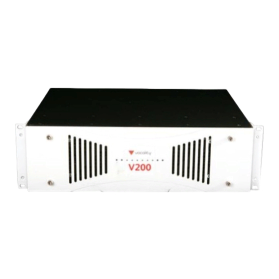
Symbols used in this manual Some items are only relevant when your V200 is used to talk to another Vocality device. Where a feature is dependent on your V200 connecting to another Vocality device the following icon is shown: Some features are only unlocked by the purchase of Feature Keys or the purchase of certain hardware options. - Page 14 User Manual for V200 Valid for V08_08.02 or V08_48.02 The V200 is the largest (3RU) and most capable multiplexer in the range, extending the rackmount format of the V150 from 3 to 10 slots. This provides the redundancy and reliability needed in the hub of a mission critical network.
- Page 15 Vocality User Manual User Manual for V200 Valid for V08_08.02 or V08_48.02 * with secure software variant only Page 5 of 114...
-
Page 16: About User Manuals
Valid for V08_08.02 or V08_48.02 About User Manuals The accuracy and clarity of our User Manuals is important to us at Vocality. If you find an error or have any queries which are not answered by our current documentation, your local Vocality support team would be happy to hear from you. -
Page 17: Functionality
Your V200 is a powerful systems multiplexer which adds density, scalability, and redundancy to the portfolio of Vocality products. It is not only conceived as a flagship unit that will support legacy V100/V50 networks but more strategically as a unit that will reliably perform as the hub of a mission-critical network. -
Page 18: Capabilities
The V200 also provides hot-swap capabilities such that line cards can be added or older cards to be replaced without affecting the networks connected to the cards in the remaining bays. -
Page 19: Cpu Card
At least one CPU card must be installed in each V200 – it is configured as Slot 0 and provides the management facilities for the entire unit. Another CPU card may be present and assigned as a redundant Slot 0 CPU card –... -
Page 20: Alarm Port
A UDP relay function enhances this by allowing communication between a remote client and a server on the home network. Users can plug their laptop into the remote V200 and log in to their home network, surf the internet and pick up E- mail. -
Page 21: Call Routing
All synchronous data channels configured with a DBA clock source are assigned to this pool, which is distributed between streams in proportion to their bit rate. Your V200 smoothly adjusts the clock speeds on all DBA ports whenever there is a change. -
Page 22: Redundancy And Hot-Swap
2.2.5 Redundancy and Hot-swap The V200 chassis and service cards are designed to provide years of reliable operation for mission-critical networks. To augment the basic robustness, all cards, including even the PSU, may be operated in pairs to provide a hot-standby for essential services. This is... -
Page 23: Network Topologies
The ability to configure multiple aggregate ports allows a vast range of topologies to be built with the V200, ranging from simple point-to-point systems at one extreme to a Star network cluster with a large number of remotes at the other. Connections may be permanent or dynamic, the choice being made by the nature of the traffic. -
Page 24: Led Meanings
Valid for V08_08.02 or V08_48.02 Figure 2-4 Shared outbound network The V200 may be used in shared outbound applications, where many remote units may wish to select a receive channel from a large outbound carrier. Often there is also a requirement for a return carrier from each site, which can be transmitted back to the hub. -
Page 25: Leds During Hot-Swap
Vocality User Manual User Manual for V200 Valid for V08_08.02 or V08_48.02 Mode LED state Meaning Aggregate Green Carrier is present Tributary Green Good data packet sent or received Aggregate Green flash Loop is detected on the port Aggregate Amber... -
Page 26: Installation
Mechanical Construction The V200 is housed in a 3U tall 19" rackmount enclosure. The enclosure comprises four parts incorporating chassis, inner front panel, outer front panel and lid. The outer front panel houses two cooling fan inlets, which must not be obstructed at any time, and ten light pipes leading to LED indicators inside. -
Page 27: Option Card Installation
User Manual for V200 Valid for V08_08.02 or V08_48.02 Figure 3-1 Identification of bays A to J on a V200 The front panel has indicators for each bay (amber or green). The meaning of these indicators is discussed in Section 2.4 . -
Page 28: Removing An Option Card
Next, either replace the blanking plate or insert a new card in the option slot. WARNING: Empty bays must be fitted with a blanking plate. Failure to ensure all bays either have a blanking plate or a card installed may cause the V200 to dangerously overheat. 3.4.2... - Page 29 Vocality User Manual User Manual for V200 Valid for V08_08.02 or V08_48.02 A second PSU card may be safely installed in an already operating chassis. The appropriate blanking plate should be removed and the new card aligned and inserted into the slot (either Bay I or Bay J) with its power switch turned off. The knurled fixings screws should be tightened before the second AC mains cord is plugged in and the switch turned on.
-
Page 30: Configuring The Unit
Configuring the Unit The following is an overview of the first few configuration steps for your unit. Step 1 Provide power and connect a computer to control your Vocality unit Figure 4-1 Connecting your unit Step 2 When prompted enter your username and password Factory defaults are Username:Vocality and Password:Vocal1ty (Note: The password uses the number 1 instead of the letter i.) -
Page 31: Port Addressing Scheme
Note: When a unit is configured as a Push Config client , the Node ID is set via the Push Config Clients menu by the hub unit. 4.1.2 Slot and Channel Numbers From the rear, the V200 is laid out as follows: Figure 4-4 Bays on V200 Page 21 of 114... - Page 32 Vocality User Manual User Manual for V200 Valid for V08_08.02 or V08_48.02 A Slot is a number which maps a card in a physical bay to a logical slot via the Slot Management menu and Channel is a number which indicates the particular port within that logical slot.
- Page 33 On standard CPU cards, channels x:10 through x:31 are used to represent IP tributaries. Again for V200 systems, the integrated router may be in the system multiple times — one for each CPU card (standard or high speed) installed. If IP is configured on a high speed CPU card in slot 3, the tributaries available are 3:10-3:99.
-
Page 34: Connecting To The Unit
Your unit should be in Normal mode. You will need to know the IP address or URL of your Vocality unit to access it via HTTP or HTTPS. The default for BASICS units is for the Downlink port to be set to 192.168.0.199. - Page 35 Vocality User Manual User Manual for V200 Valid for V08_08.02 or V08_48.02 Figure 4-5 Banner page on the web interface HTTP authentication will be used to validate the connected user, refer to the Password Protection section for further details. Note: Unless HTTPS is used, your username and password will be transmitted in the clear.
-
Page 36: Using The M&C Or Console Port
Note: After any action which should alter the menus available, for instance installing a new card in a V200 or adding a new route map, use the refresh page function in your browser to force an update of the Map zone. - Page 37 Vocality User Manual User Manual for V200 Valid for V08_08.02 or V08_48.02 Figure 4-7 HyperTerminal connection Click on the Configure button to set HyperTerminal to operate at 9600bps, 8 data bits, no parity, one stop bit with no flow control: Figure 4-8 HyperTerminal COM port settings The unit supports VT100 terminal emulation.
- Page 38 Version 8. This allows the unit to be upgraded with any version 8 (or before) software created before 1st January 2015. To update the license information you would need to contact your Vocality support representative with the serial number of your Vocality unit. They can issue the updated license information.
-
Page 39: Password Protection
Administrator. By default there is one administrator account with the username 'Vocality', for which the password is 'Vocal1ty'. You will be prompted for this username and password before you are allowed to access the unit, however you log in. -
Page 40: Login And Logout Scheme
Vocality User Manual User Manual for V200 Valid for V08_08.02 or V08_48.02 User accounts and related parameters must be configured on remote units. They are not part of the Push Config which may be downloaded. 4.3.1 Login and logout scheme If accounts are enabled then on the M&C or console port the following prompts are... -
Page 41: Logging In From Ssh
Once entered, the user is given Administrator privileges to allow him/her to change the password of any other account. A Superuser password can only be supplied by contacting your local Vocality support team. -
Page 42: Ssh Password Mode
Once this validation has happened, the unit presents any configured welcome message and then re-prompts for the password. Logout from the Vocality unit will leave the SSH session active – so you can login again with the same or different password from that used to open the SSH session. -
Page 43: Standard Configuration Or Push Config
As an alternative to the manual approach, any BASICS, V25, V50plus or V150 unit may receive their configuration settings automatically from a V150 or a V200 hub unit using a mode known as Push Config. In this case, the hub unit contains all of the configurations for the clients in the network and pushes them out using a proprietary protocol at the start of the day. - Page 44 Vocality User Manual User Manual for V200 Valid for V08_08.02 or V08_48.02 All menus contain certain key information, highlighted in the following figures. If you are using the M&C or console port: From the Main menu other menus may be accessed by moving the highlighted cursor up or down the list of options and pressing <Enter>.
- Page 45 Vocality User Manual User Manual for V200 Valid for V08_08.02 or V08_48.02 Figure 4-12 Example menu on the web interface Page 35 of 114...
-
Page 46: Getting Started
User Manuals, whenever a common difficulty is identified by our support teams. Should you have queries which are not answered by our current documentation, your local Vocality support team would be happy to hear from you. E- mail support@vocality.com. -
Page 47: Capturing And Loading Configurations
Valid for V08_08.02 or V08_48.02 Capturing and loading configurations Capturing Vocality configuration files is useful for speeding up the configuration of identical multiple units. You can configure and test a single unit, then the configuration can be captured and uploaded to other units. -
Page 48: Technique
Vocality User Manual User Manual for V200 Valid for V08_08.02 or V08_48.02 Figure 5-2 ASCII setup 5.1.3 Technique You will need to start at the Banner page on M&C interface and enter the commands below. (Replace nodename by the node name of the unit, not the node ID.) 1. -
Page 49: To Load A Configuration When The Unit Is In A Default State39
10. Check the configuration in the menus is correct. Upgrading your software - via menus This section explains how you can upgrade the software on a V150/V200 using the menu structure. If you are unsure about using VNUT refer to Section 5.5 Installing the Vocality Network Upgrade Tool (VNUT) and if you are unsure whether the Boot ROMs are the correct minimum version for your new software refer to Section 5.3 Upgrading Boot... -
Page 50: Upgrading The Software
5.2.2 Upgrading the software To upgrade the software on the V150/V200 you need to enter the IP address of the PC in the field 'TFTP Server' displayed by the Vocality TFTP application (VNUT) on the PC. Enter the software file name in the field 'Upgrade Version', in the lower half of the screen shown in Figure 5-4 . - Page 51 Valid for V08_08.02 or V08_48.02 Figure 5-5 VNUT showing upgrade progress On the V150/V200, the progress is shown: Figure 5-6 Software Management menu showing update progress The new software will be added to your list of SOFTWARE VERSIONS PRESENT with an <UPGRADE>...
-
Page 52: Upgrading Boot Rom Firmware
Unit configurations are maintained during software updates. Upgrading Boot ROM Firmware This section explains how you can upgrade the Boot ROMs. You may also need to refer to Section 5.5 Installing the Vocality Network Upgrade Tool (VNUT). 5.3.1 Confirm Boot ROM firmware version Before you begin, check the Boot ROM firmware version by issuing the following command at the Debug prompt (see section 5.7 Issuing debug commands):... -
Page 53: Renewing Your Software Maintenance Licence Key
Pre-requisites All hardware must have a valid warranty or a support agreement in place. If this agreement is not in place, you can purchase one. To update your licence information please contact your local Vocality support representative. 5.4.2 Licence Configuration You can do this from a factory defaulted unit or a running operational unit. -
Page 54: Single Unit
Version 8. This allows the unit to be upgraded with any version 8 (or before) software created before 1st January 2015. To update the license information you would need to contact your Vocality support representative with the serial number of your Vocality unit. They can issue the updated license information. -
Page 55: Special Case: Upgrading From Pre-Version 6 Software
The Vocality Network Upgrade Tool (VNUT) is a TFTP server that is quick and simple to install. It allows all current Vocality devices to be upgraded via TFTP. If you would prefer to use another TFTP server please contact your local Vocality support representative for advice. -
Page 56: Installation
Installation You will find the application ‘VNUT.msi’ on the software distribution disk or you can download it from the Vocality website at http://www.vocality.com To install, open the folder containing the file and double-click on the application name. The following page will be displayed: Figure 5-9 Welcome to VNUT setup When you choose Next you will see, the licence agreement. - Page 57 Vocality User Manual User Manual for V200 Valid for V08_08.02 or V08_48.02 Figure 5-11 Confirm VNUT installation If you wish to cancel the installation, choose Cancel. If you want to change the location the TFTP software will be installed in, choose Previous and the page shown in Figure 5- 10 will be displayed again.
-
Page 58: Vocality Operating System Software
Figure 5-13 VNUT installation complete 5.5.3 Vocality Operating System software You will need to copy the new Vocality Operating System (VOS) software to the appropriate folder. In this example, the software is assumed to be copied to C:\TFTPBoot. You will need to add a new folder to your C: drive, using Windows Explorer, and rename it TFTPBoot. -
Page 59: Specifying The Upgrade Directory
Figure 5-15 VNUT reporting valid IP address 5.5.5 Specifying the upgrade directory To select the directory where the Vocality Operating System is stored, you will need to choose Options. The following page is displayed: Page 49 of 114... - Page 60 Vocality User Manual User Manual for V200 Valid for V08_08.02 or V08_48.02 Figure 5-16 Select VNUT Options > Directory When you select Directory. The following menu will be displayed: Page 50 of 114...
-
Page 61: Settings
Figure 5-17 Browse for TFTP folder location Select the 'C:\TFTPBOOT', as shown above, and choose OK. CAUTION: For security reasons, you are advised to store the upgrade software in C:\TFTPBOOT. Vocality advises against ever using the root directory (C:\) for storing the upgrade software. 5.5.6 Settings To adjust the settings, you will need to choose Options >... - Page 62 Vocality User Manual User Manual for V200 Valid for V08_08.02 or V08_48.02 Figure 5-18 Going to the VNUT Options > Settings menu When you select Settings. The following menu will be displayed. Check the 'windowing' box to speed up the upgrade.
-
Page 63: Security Settings
The VNUT TFTP Server software has security settings, which allow you to limit access to the TFTP Server (PC) to TFTP clients (such as Vocality units) with an IP address within a specified range or to specific IP addresses in a list. If security settings are not used, then any TFTP client (such as a Multiplexer or a PC) could put files onto or copy files from the TFTP Server. - Page 64 Vocality User Manual User Manual for V200 Valid for V08_08.02 or V08_48.02 Figure 5-20 VNUT security menu - range example In Figure 5-20 , only TFTP Clients with an IP address in the range 192.168.0.30 to 192.168.0.120 can either copy files from, or put files onto the PC.
-
Page 65: Issuing Tty Commands
Vocality User Manual User Manual for V200 Valid for V08_08.02 or V08_48.02 In Figure 5-21 only clients with an IP address of 192.168.0.35 or 192.168.0.43 are authorised. Issuing TTY commands Your unit can be configured through the menus, without the need to issue any TTY commands. -
Page 66: Issuing Debug Commands
Vocality User Manual User Manual for V200 Valid for V08_08.02 or V08_48.02 Queries - these are requests to provide details of how parameters are currently configured. Configurations - these are requests to change an existing parameter or add a ... - Page 67 Vocality User Manual User Manual for V200 Valid for V08_08.02 or V08_48.02 This will take you to the debug command prompt 'Dbg>'. Figure 5-23 Entering debug mode Type help then press <Enter> for a list of all valid debug commands. Commands are not case-sensitive.
- Page 68 Vocality User Manual User Manual for V200 Valid for V08_08.02 or V08_48.02 Debug Command IP AGG CLEAR STATS Clear statistics for IP Aggs IP AGG STATS Report statistics for IP Aggs IPCONFIG Show IP address configuration IP FILT STATS Report statistics for IP Filters...
-
Page 69: Managing Your Unit From Linux
Vocality support engineers. Managing your unit from Linux You may wish to manage your Vocality devices from a Linux-based PC or laptop. Whilst this is possible there are two potential issues: Vocality tools, such as VNUT are only available for Windows, so an alternative ... -
Page 70: Telnet Access To The Vocality Console
5.8.2.2 C-KERMIT Although it is possible to customise Telnet to work better when connecting to Vocality devices, a more satisfactory method is to use C-KERMIT which is a powerful communication program supporting scripting and much more. C-KERMIT is freely available for most UNIX derivations including Linux. -
Page 71: Accessing The Vocality Console Via The Port
User Manual for V200 Valid for V08_08.02 or V08_48.02 You will now be connected to the Vocality device and should find that the cursor keys and <Ctrl> key sequences all work as expected. The kermit <Esc> key is <Ctrl> <\>. -
Page 72: Linux Server Setup
It is up to the user to take all necessary precautions to ensure that only the correct software is loaded on to a Vocality device. Any device which has had incorrect software loaded will become unusable and will have to be returned to Vocality for repair. -
Page 73: Client Configuration
You will need to configure the client correctly in order to poll the unit and/or to receive traps. You will need to load the two Vocality MIBs into the client application to correctly interpret the traps. These can be obtained by emailing your local Vocality support representative. -
Page 74: Configuring Ipsec Tunnels
Vocality User Manual User Manual for V200 Valid for V08_08.02 or V08_48.02 INET-ADDRESS-MIB http://www.simpleweb.org/ietf/mibs/modules/IETF/txt/INET- ADDRESS-MIB IANA-RTPROTO-MIB http://www.simpleweb.org/ietf/mibs/modules/IANA/txt/IANA- RTPROTO-MIB or http://www.iana.org/assignments/ianaiprouteprotocol-mib These files need to be loaded into Castlerock in this order. To view the IP routing table within Castlerock you would then select SNMP Mibs >... -
Page 75: Protocols And Algorithms
> IKE DH Groups menu and ‡IP > IPSec > IKE Auth Algorithms menu 5.10.2 IPSec tunnels Secure VPNs can be created between two Vocality units or a Vocality device and another IPSec device through the use of IPSec tunnels. Alternatively it is possible to use IP aggregates secured using IPSec transport encryption. -
Page 76: Creating An Ipsec Tunnel With Pre-Shared Keys
Vocality User Manual User Manual for V200 Valid for V08_08.02 or V08_48.02 5.10.2.1 Creating an IPSec tunnel with pre-shared keys Step 1 First, go to the ‡IP > IPSec > Keys menu and select <ADD KEY>. Assign a name to the description field and then enter a pre-shared key. - Page 77 Vocality User Manual User Manual for V200 Valid for V08_08.02 or V08_48.02 Figure 5-27 IPSec > Tunnel Security Associations menu - pre-shared keys Step 3 Next you will need to go to IP > Service Management > Address Definitions menu and select <NEW ENTRY>...
-
Page 78: Creating An Ipsec Tunnel With Ike
Vocality User Manual User Manual for V200 Valid for V08_08.02 or V08_48.02 Step 5 Finally, go to ‡Tunnelling Policies > IPSec Tunnel Policy menu (see Figure 5-29 ). Set SourceAddr to one of your local address names, assigned in Step 3 or 'ANY'. - Page 79 Vocality User Manual User Manual for V200 Valid for V08_08.02 or V08_48.02 Step 2 Then, go to the ‡IP > IPSec > Keys menu (see Figure 5-26 ) and select <ADD KEY>. Assign a name to the description field and then enter a pre-shared key.
-
Page 80: Logs
Vocality User Manual User Manual for V200 Valid for V08_08.02 or V08_48.02 Step 6 Finally, go to ‡Tunnelling Policies > IPSec Tunnel Policy menu (see Figure 5-29 ). Set SourceAddr to one of your local address names, assigned in Step 4 or 'ANY'. -
Page 81: Access Table Entry
User Manual for V200 Valid for V08_08.02 or V08_48.02 This section explains how you can configure an SSH server on Vocality units, once you have set up the menus below the ‡SSH Server menu to permit either a password or pre-shared key form of SSH. -
Page 82: Diagnostics
5.12 TCP optimisation While it is almost impossible to eliminate latency and errors over satellite networks, their impact can be minimised. Vocality’s PEP accelerates application traffic by eliminating: The impact of high latency in wasted WAN capacity and link under-utilisation ... - Page 83 Valid for V08_08.02 or V08_48.02 Figure 5-35 Standard TCP session When a pair of Vocality units is introduced in the connection path between the two machines then they can be configured to run the performance enhancing proxy: Figure 5-36 PEP introduced to TCP session...
-
Page 84: How To Deploy Pep
You can configure an IP connection as an aggregate link. The IP aggregate enables use of an IP connection as a normal aggregate link, to multiplex voice and data between two Vocality units. Whilst the voice is carried over an IP link, this is not industry standard Voice over IP (VoIP). -
Page 85: Software Configuration
Vocality User Manual User Manual for V200 Valid for V08_08.02 or V08_48.02 5.13.2 Software configuration The steps which follow, describe the configuration sequence for an IP aggregate. First, you will need to configure the IP port with a valid IP address on the IP >... -
Page 86: Routing
You will need to ensure the unit has a route to the peer address configured. You will then need to enter a route in the Routing menu, so that tributaries can be directed down the IP aggregate: the IP aggregate does not fully exist until a Vocality route is defined which uses it. -
Page 87: Bandwidth Calculations
As long as the total Vocality payload will fit into the UDP payload, then the following rule of thumb may be used: where: The following table contains bandwidth requirements based on the above. -
Page 88: Clock Hierarchy
Each port generates clocks for its own use. Those ports need to be referenced to a common clock. Within your Vocality unit one or two clocks, known as GC1, and where available GC2, can be used to synchronize ports in each node. GC1 and GC2 allow two discrete and independent clock hierarchies to be used. -
Page 89: Example
Valid for V08_08.02 or V08_48.02 your application requires the use of two global clocks we would recommend that you contact your local Vocality support representative for advice. Using this technique, it is possible to onward-link a clock without degradation from any port to any other in a network, even if it is located in another chassis or even in a remote location via a satellite link. - Page 90 Vocality User Manual User Manual for V200 Valid for V08_08.02 or V08_48.02 Table 5-4 Slot 0 Data menu, identical for Unit 1 and Unit 2 Define clocking for the unit to come from the aggregate link: Table 5-5 Clocking menu, identical for Unit 1 and Unit 2...
-
Page 91: Terminal Timing
DTE to DCE, they arrive in phase and reliable reception by the DCE port is also assured. All Vocality DTE ports drive TT with the transmit data clock for this reason. It is expected that a TT clock signal will be used, unless connected equipment is unable to support this signal. -
Page 92: Phase-Locked Loops (Plls)
Vocality User Manual User Manual for V200 Valid for V08_08.02 or V08_48.02 Figure 5-44 Terminal timing signals 5.14.6 Phase-Locked Loops (PLLs) All data ports have access to a pool of Phase-Locked Loops (PLLs) for the independent derivation of RXC or TXC. The reference clock for the PLLs is derived from either the GC1 or the GC2 global clock busses as selected on the ‡Data menu. -
Page 93: Transmit Clocks
Vocality User Manual User Manual for V200 Valid for V08_08.02 or V08_48.02 this clock comes from the RXC pin. TXC The RXC clock comes from whatever source has been selected for the TXC direction. In the particular case where the port is in DTE mode and the TXC clock has been set to "RXC", then this option uses the TXC port pin. -
Page 94: Hardware Configuration
Vocality User Manual User Manual for V200 Valid for V08_08.02 or V08_48.02 This section assumes you are familiar with configuring Vocality equipment and have a knowledge of configuring and using the Digital Voice cards. 5.15.1 Hardware configuration Vocality V150 or V200 with one or more Digital Voice Cards. -
Page 95: Testing
Vocality User Manual User Manual for V200 Valid for V08_08.02 or V08_48.02 Figure 5-46 Digital Voice menu showing correct settings for external clocking. When setup in this way, the data transmitted on this Digital Voice interface will be clocked out using GC2, which is in turn locked to whichever of the two interfaces X or Y is active. - Page 96 Vocality User Manual User Manual for V200 Valid for V08_08.02 or V08_48.02 Figure 5-47 System settings for Unit 0 Figure 5-48 System settings for Unit 1 The settings for Node ID are critical – they must be set to different values for the units to communicate correctly.
- Page 97 Vocality User Manual User Manual for V200 Valid for V08_08.02 or V08_48.02 Figure 5-49 Clocking settings for Unit 0 Figure 5-50 Clocking settings for Unit 1 The Data settings for the units are as follows: Page 87 of 114...
- Page 98 Vocality User Manual User Manual for V200 Valid for V08_08.02 or V08_48.02 Figure 5-51 Data configuration settings for Unit 0 Figure 5-52 Data configuration settings for Unit 1 Unit 0 is configured to generate a transmit link clock of 128kbps ('Int'), which is used internally as the GC1 reference (Clocking menu GC1 source) and also received by Unit 1 and used as the GC1 reference (Clocking menu GC1 source).
-
Page 99: Using Static Routes
Node 3 networks will only communicate with stations on the 1.1.1.0, 1.1.2.0 and 1.1.3.0 networks, and nothing beyond. The dynamic bandwidth allocation and MTU for all V200 channels is set at 256000. A network diagram of this example configuration network is... - Page 100 Vocality User Manual User Manual for V200 Valid for V08_08.02 or V08_48.02 Figure 5-54 IP > Networks menu for Node1 Figure 5-55 IP > IP Static Route Table for Node1 Page 90 of 114...
- Page 101 Vocality User Manual User Manual for V200 Valid for V08_08.02 or V08_48.02 Figure 5-56 IP > Networks menu for Node2 Figure 5-57 IP > IP Static Route Table for Node2 Page 91 of 114...
-
Page 102: Use With Satellite Modems
The unit is often used in combination with satellite modems to provide telecommunications links between remote sites. This example describes the use of the V200 with a Paradise Datacom P300 modem that is fitted with the standard P1440 interface in RS422 mode, thereby allowing the use of the standard RS422/RS449 cable... - Page 103 'Direct' mode. The standard cable should be used with other modems. The configuration concept is to use one unique clock in the system as generated by Modem 0 (connected to the V200 with Node ID '0'), with all other clocks derived from this: Figure 5-60 Satellite modem configuration concept In this example, port 1 on slot 5 is used on both units.
- Page 104 Vocality User Manual User Manual for V200 Valid for V08_08.02 or V08_48.02 Figure 5-61 System settings Unit 0 Figure 5-62 System settings Unit 1 The settings for Node ID are critical – they must be set to different values for the units to communicate correctly.
- Page 105 Vocality User Manual User Manual for V200 Valid for V08_08.02 or V08_48.02 Figure 5-63 Clocking settings Unit 0 Figure 5-64 Clocking settings Unit 1 The Data Configuration settings for the units are as follows: Page 95 of 114...
- Page 106 ('RXC') and given back to modem as Terminal Timing. It is then sent over the satellite link to Modem 1, which recovers the receive clock and outputs it to V200 Unit 1. Unit 1 is configured to accept this receive clock ('Ext'), to use it as the GC1 reference (GC1 source in Clocking menu) and then turn it around (Tx clock set to 'Rxc') and output it back to Modem 1 as Terminal Timing ('TT').
-
Page 107: Modem Settings
GC1 as its reference for generating the Rx router clock. To go one stage further and operate Port 2 dynamically, the Rx clock source is set to 'DBA'. This allows the V200 to smoothly vary the Rx clock on Port 2 according to traffic demand. - Page 108 Vocality User Manual User Manual for V200 Valid for V08_08.02 or V08_48.02 Figure 5-67 Network configurations possible when DHCP server mode is OFF In Server mode, the unit makes use of an embedded DHCP server that will respond to received requests from clients:...
- Page 109 Figure 5-69 IP > DHCP Server menu - server mode In Relay mode, DHCP requests are relayed to a remote DHCP server through the Vocality unit – requests are relayed to the addresses configured in the primary and secondary server addresses in the DHCP server configuration:...
-
Page 110: Configuring Broadcast Services
5.20 Configuring broadcast services Vocality units can be used in point-to-multipoint networks, where a number of remotes may wish to receive the same data. In the example below, the hub unit is connected to a number of four wire voice feeds and each remote has chosen to listen to a selection from these. -
Page 111: Configuration
Vocality User Manual User Manual for V200 Valid for V08_08.02 or V08_48.02 5.20.2 Configuration Figure 5-72 above shows one hub unit and three remotes. All arrows refer to audio channels and not aggregates. Each remote is providing a separate transmit audio, shown by the feed going back to the hub. -
Page 112: Vocality Routing Settings
Vocality User Manual User Manual for V200 Valid for V08_08.02 or V08_48.02 Figure 5-73 Voice menu settings - Node 0 Figure 5-74 shows the voice settings on node 1. Voice channel 1 is configured to transmit as broadcast channel 1 and receive broadcast channel 0 . The other remotes need to be configured in a similar way but Node 2 will transmit on broadcast channel 2 and Node 3 on broadcast channel 3. -
Page 113: Routing Broadcast Traffic Between Slots
– it is not available for use by other calls. A broadcast group may be assigned a bandwidth of zero, then it will rely on the Vocality overhead to carry the broadcast traffic. - Page 114 Vocality User Manual User Manual for V200 Valid for V08_08.02 or V08_48.02 Figure 5-75 Vocality serial transmit broadcast trib settings - Node 0 Page 104 of 114...
Need help?
Do you have a question about the V200 and is the answer not in the manual?
Questions and answers