Table of Contents
Advertisement
Quick Links
Introduction
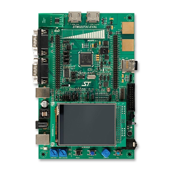
The STM32373C-EVAL evaluation board is designed as a complete demonstration and
development platform for STMicroelectronics' ARM cortex-M4 core-based
STM32F373VCT6 microcontroller. It features two I2Cs, three SPIs, three USARTs, one
CAN, one CEC controller, one 12-bit ADC, three 16-bit sigma delta ADCs, three 12-bit
DACs, internal 32-KByte SRAM and 256-KByte Flash, touch sensing, USB FS, and JTAG
debugging support. This evaluation board can be used as a reference design for user
application development but it is not considered as the final application.
The full range of hardware features on the board can help the user evaluate all peripherals
(USB FS, USART, audio DAC, microphone ADC, color LCD, IrDA, LDR (light-dependent
resistor), MicroSD card, HDMI CEC, ECG (electrocardiogram), pressure sensor, CAN, IR
(infrared) transmitter and receiver, EEPROM, touch slider, temperature sensor, etc.) and
develop their own applications. Extension headers make it possible to easily connect a
daughterboard or wrapping board for a specific application.
An ST-LINK/V2 is integrated on the board as an embedded in-circuit debugger and
programmer for the STM32 MCU.
Figure 1.
Table 1.
Evaluation tools
September 2012
STM32373C-EVAL evaluation board
Applicable tools
Type
Doc ID 023566 Rev 1
STM32373C-EVAL evaluation board
STM32373C-EVAL
UM1564
User manual
Part number
www.st.com
1/66
Advertisement
Table of Contents

Subscribe to Our Youtube Channel
Related Manuals for ST STM32373C-EVAL


Summary of Contents for ST STM32373C-EVAL
-
Page 1: Table 1. Applicable Tools
Extension headers make it possible to easily connect a daughterboard or wrapping board for a specific application. An ST-LINK/V2 is integrated on the board as an embedded in-circuit debugger and programmer for the STM32 MCU. Figure 1. -
Page 2: Table Of Contents
Contents UM1564 Contents Overview ..........6 Features . - Page 3 Schematics ..........43 Appendix A STM32373C-EVAL pinout ....... . . 60 Appendix B Mechanical dimensions.
- Page 4 STM32373C-EVAL pinout ........
- Page 5 STM32373C-EVAL evaluation board layout ........10...
-
Page 6: Overview
Demonstration software is preloaded on the board’s Flash memory for easy demonstration of the device peripherals in standalone mode. For more information and to download the latest version available, please refer to the STM32373C-EVAL demonstration software available on www.st.com. 6/66... -
Page 7: Order Code
UM1564 Overview Order code To order the STM32F373VCT6 evaluation board, use the order code STM32373C-EVAL. Delivery recommendations Some verification of the board is needed before using it for the first time to make sure that nothing was damaged during shipment and that no components are unplugged or lost. -
Page 8: Hardware Layout And Configuration
Hardware layout and configuration UM1564 Hardware layout and configuration The STM32373C-EVAL evaluation board is designed around the STM32F373VCT6 (100- pin LQFP package). The hardware block diagram, Figure 2, illustrates the connection between the STM32F373VCT6 and the peripherals (color LCD, touch slider, USB FS connector, temperature sensor, USART, IrDA, audio, EEPROM, RF EEPROM, MicroSD card, and embedded ST-LINK). -
Page 9: Figure 2. Hardware Block Diagram
USART2 transceiver connector Voltage LEDs GPIO USART translator IrDA transceiver Wakeup, tamper . STM32F373VCT6 button Embedded USB type B ST-LINK/V2 connector Photo-R Comparator JTAG JTAG and trace Touch slider TS controller connector 2-pin DAC/ADC Micro SD connector card Voltage SPI3... -
Page 10: Figure 3. Stm32373C-Eval Evaluation Board Layout
Hardware layout and configuration UM1564 Figure 3. STM32373C-EVAL evaluation board layout RF EEPROM daughter board HDMI SOURCE HDMI SINK Touch Slider connector CN13,CN14 TS1 & TS2 Extension ECG Probe header Pressure Sensor STM32F373VCT6 MicroSD card CN12 USART2 IrDA CN16 CN15... -
Page 11: Development And Debug Support
Hardware layout and configuration Development and debug support Version 2 of the ST-LINK (ST-LINK/V2) is embedded on the board. This tool allows onboard program loading and debugging of the STM32F373VCT6 using the JTAG or SWD interface. Third-party debug tools are also supported using the JTAG/SWD connector (CN17) or the ETM trace connector (CN15). -
Page 12: Power Supply
UM1564 Power supply STM32373C-EVAL evaluation board is designed to be powered by a 5 V DC power supply and is protected by PolyZen U26 from damage caused by overvoltage and overcurrent fault conditions. It is possible to configure the evaluation board to use any of following four power supply sources: ●... - Page 13 JP17 and connect the extended reference to pin 1 (the top pin of JP17). LED LD8 is lit (red) when the STM32373C-EVAL evaluation board is powered by a 5-V DC power supply. LED LD6 is lit (red) when the microcontroller is powered by VDD < 2.4 V (low voltage).
-
Page 14: Power Modes
Hardware layout and configuration UM1564 Power modes A total of three power modes are supported on the board and can be configured by setting the related jumpers JP12 and JP13 as described below in Table 4. The power modes are as follows: ●... -
Page 15: Clock Sources
The recommended AC220 V to DC5 V power adapter is PSU-5V2A. It is not included with the board but can be ordered from ST as a separate item. You can also use another equivalent 5 V power adapter (polarity compatible with CN18) to power the STM32373C- EVAL board via the CN18 power jack on the board. -
Page 16: Reset Source
Hardware layout and configuration UM1564 Reset source The reset signal of the STM32373C-EVAL evaluation board is “low active” and the reset sources (see Figure 3) include: ● Reset button B1 ● Debugging tools from JTAG/SWD connector CN17 and ETM trace connector CN15 ●... -
Page 17: Audio
This is the default setting: it is not fitted. Audio The STM32373C-EVAL evaluation board supports stereo audio playback by an audio DAC CS43L22 connected to the I2S port and one channel of the STM32F373VCT6 DAC. The microphone is connected to the ADC input of STM32F373VCT6 through a microphone amplifier. -
Page 18: Usb
● IrDA transceiver (U12) They are connected to USART2 of the STM32F373VCT6 on the STM32373C-EVAL evaluation board. The Bootloader_RESET signal (which is shared with the CTS signal) and the Bootloader_BOOT0 signal which is shared with the demand signal repository (DSR) signal) are added on the RS-232 connector, CN12, for ISP support. -
Page 19: Touch Sensing Slider
C123 and the firmware so they are adapted to a voltage range of 2.0 V to 3.6 V of VDD. The touch slider is not functional when the STM32373C-EVAL is powered on Power mode 3 because some IOs are also powered by the VDDA domain. -
Page 20: Microsd Card
Hardware layout and configuration UM1564 2.11 MicroSD card The 2-Gbyte (or more) MicroSD card connected to the SPI3 port (which is shared with the color LCD) of the STM32F373VCT6 is available on the evaluation board. It can be enabled by the chip select signal (PE2). This signal should be set as an open-drain output pin in the STM32F373VCT6. -
Page 21: Can
When JP2 is fitted, the CAN terminal resistor is enabled. Default setting: not fitted. CAN operates correctly when VDD > 3 V. 2.15 HDMI CEC Two HDMI connectors, CN1 and CN2, are available on the STM32373C-EVAL evaluation board. ● Connector CN1 is a HDMI sink connector with: –... -
Page 22: Ir Transmitter And Ir Receiver
2.17 Electrocardiogram demonstration The electrocardiogram (ECG) demonstration is implemented on the STM32373C-EVAL evaluation board. There are two ECG electrodes, TS1 and TS2, on the board for fingers from the right and left hands of the human body. The first stage of the ECG amplifier circuit is an instrument amplifier INA333 (U2). -
Page 23: Pt100 Temperature Sensor
2.18 PT100 temperature sensor There is a current source circuit on the STM32373C-EVAL evaluation board to provide a fixed 1 mA current (when VDD = 3.3 V) to the platinum probe PT100 (R30). The R30 voltage level is directly applied to the sigma delta ADC of the STM32F373VCT6, through PE7, to measure the temperature value on PT100. -
Page 24: Table 16. Temperature Sensor Voltage Range
Hardware layout and configuration UM1564 Equation 2 (since G OUTA1 OUTA2 Equation 3 OUTA2 PT100 Equation 4 – OUTA1 PT100 Equation 5 ⁄ Rref The voltage on the ADC input is given in Equation Equation 6 × ⁄ × ⁄ ×... -
Page 25: Table 17. Pt100-Related Jumper
UM1564 Hardware layout and configuration A 100 Ω 0.1% resistor, R121, is used to calibrate PT100 by setting JP18. Note: Table 17. PT100-related jumper Jumper Description and jumper setting The 100-ohm 0.1% resistor is connected for calibration when JP18 is set as shown to the right: JP18 PT100 resistor is connected to measure temperature when JP18 is set as shown to the right:... -
Page 26: Pressure Sensor
An absolute pressure sensor with 1000 HP, full scale MPX2102, and an analog front end is implemented on the STM32373C-EVAL board. The output differential pair is connected to the sigma delta ADC in the STM32F373VCT6 via PE8 (P) and PE9 (N). - Page 27 UM1564 Hardware layout and configuration The operational amplifier differential input voltage provided by the pressure sensor is given Equation Equation 10 × × – Where: ● = the pressure measured ● K = sensitivity of the sensor (40 mV for VDD = 10 V and 1000 HPa) The ADC output is related to the differential voltage by Equation Equation 11...
-
Page 28: Analog Input
2.21 Potentiometer A 10K ohm potentiometer RV3 is connected to comparator 2 through PA3 and ADC through PB1 (default connection), as shown in Figure Figure 6. STM32373C-EVAL potentiometer ADC_SAR_AIN9 ADC_SD1_AIN3P-AIN2M VDDA GP comparator GPCOMP2_IN+ GPCOMP2_IN- Band gap 1.2 V... -
Page 29: Ldr
UM1564 Hardware layout and configuration 2.22 A light dependent resistor (LDR) is connected to ADC or comparator 1 through PA1, as shown in Figure Figure 7. STM32373C-EVAL LDR VDDA ADC_SAR_IN1 GP comparator LDR_OUT GPCOMP2_IN+ GPCOMP2_IN- Band gap 1.2 V MS30944V1 2.23... -
Page 30: Display And Input Devices
Hardware layout and configuration UM1564 2.24 Display and input devices The 240x320 TFT color LCD connected to port SPI3 of STM32F373VCT6 (shared with the MicroSD card) and four general-purpose color LEDs (LD1, LD2, LD3, LD4) are available as display devices. LED LD9 is connected with PA7 to show the status of comparator 2 when debugging. -
Page 31: Connectors
UM1564 Connectors Connectors HDMI sink connector CN1 Figure 8. HDMI sink connector CN1 (front view) Table 20. HDMI sink connector CN1 Pin number Description Pin number Description 1, 3, 4, 6, 7, 9, TMDS differential signal pair I2C1_SCL (PB6) 10, 12 connected to CN2 2, 5, 8, 11, 17 I2C1_SDA (PB7) -
Page 32: Rf Eeprom Daughterboard Connector Cn3
Connectors UM1564 Table 21. HDMI source connector CN2 Pin number Description Pin number Description 1, 3, 4, 6, 7, 9, TMDS differential signal pair I2C2_SCL (PA9) 10, 12 connected to CN1 2, 5, 8, 11, 17 I2C2_SDA (PA10) HDMI_5V_Source from power CEC (PB8 through NMOS) switch U1 HPD (PD7) -
Page 33: Microsd Connector Cn7
UM1564 Connectors MicroSD connector CN7 Figure 12. MicroSD connector CN7 Table 24. MicroSD connector CN7 Pin number Description Pin number Description Vss/GND MicroSDcard_CS (PE2) MicroSDcard_DOUT (PC11) MicroSDcard_DIN (PC12) +3V3 MicroSDcard_CLK (PC10) MicroSDcard_detect (PE3) Sigma Delta ADC connector CN9 Figure 13. Sigma Delta ADC connector CN9 (top view) MS30945V1 Sigma Delta ADC connector CN9 Table 25. -
Page 34: Sar Adc Dac Connector Cn10
Connectors UM1564 SAR ADC DAC connector CN10 Figure 14. SAR ADC DAC connector CN10 (top view) MS30945V1 SAR ADC DAC connector CN10 Table 26. Pin number Description Pin number Description AGND ADC-DAC input & output PA5 SAR ADC DAC connector CN11 Figure 15. -
Page 35: Rs-232 Connector Cn12
UM1564 Connectors RS-232 connector CN12 Figure 16. RS-232 connector CN12 (front view) 1 2 3 4 5 6 7 8 9 Front view MS19140V2 RS-232 connector CN12 with HW flow control and ISP support Table 28. Pin number Description Pin number Description Bootloader_BOOT0 RS232_RX (PD6) -
Page 36: Daughterboard Extension Connectors Cn13 And Cn14
Daughterboard extension connectors CN13 and CN14 Two 50-pins male header connectors CN13 and CN14 can be used to connect with daughterboard or standard wrapping board to STM32373C-EVAL evaluation board. All GPI/Os are available on them. The space between these two connectors and position of power, GND and RESET pins are defined as a standard which allows to develop common daughterboards for several evaluations boards. - Page 37 UM1564 Connectors Table 29. Daughterboard extension connector CN13 (continued) How to disconnect from function block Description Alternative function on STM32373C-EVAL board I2S_WS I2S_MCK I2C2_SMB Remove R215. I2C2_SCL Keep JP4 on open. PA12 USB_DP Remove R75. PA14 SWCLK/JTCK Disconnect CN15, CN17.
-
Page 38: Table 30. Daughterboard Extension Connector Cn14
Connectors UM1564 Table 30. Daughterboard extension connector CN14 How to disconnect from function block Description Alternative function on STM32373C-EVAL board PD14 SLIDER_3 Remove R11, close SB9. PD11 AUDIO_RST Remove R79. PC13 RESET# PB15 PB10 PE14 PRESSURE_TEMPERATURE Remove R196. PE11 ADC_SD Remove R39. - Page 39 UM1564 Connectors Table 30. Daughterboard extension connector CN14 (continued) How to disconnect from function block Description Alternative function on STM32373C-EVAL board PE12 Remove R14, close SB13. PE10 OSC_OUT Remove R38, close SB24. RTD_IN Remove C11, C17, R34, close SB18. MIC_IN Remove R136.
-
Page 40: Etm Trace Debugging Connector Cn15
Connectors UM1564 3.11 ETM Trace debugging connector CN15 Figure 17. ETM Trace debugging connector CN15 (top view) 19 17 12 10 MS30946V1 ETM Trace debugging connector CN15 Table 31. Pin number Description Pin number Description VDD power TMS/PA13 TCK/PA14 TDO/PB3 TDI/PA15 RESET# TraceCLK/PE2... -
Page 41: Jtag/Swd Debugging Connector Cn17
RESET# DBGRQ DBGACK 3.14 Power connector CN18 The STM32373C-EVAL evaluation board can be powered by a DC 5V power supply via the external power supply jack connector (CN18) shown in Figure 20. The central pin of CN18 must be positive. -
Page 42: St-Link/V2 Programming Connector Cn19
A 3.5 mm stereo audio jack CN21 connected to audio DAC is available on STM32373C- EVAL board. 3.18 ST-LINK/V2 USB type B connector CN22 USB connector CN22 is used to connect the embedded ST-LINK/V2 to the PC for board- debugging purposes. Figure 21. USB type B connector CN22 (front view) Table 34. -
Page 43: Schematics
Figure 33: STM32373C-EVAL Touch slider on page 55 ● Figure 34: STM32373C-EVAL I2C peripherals on page 56 ● Figure 35: STM32373C-EVAL PT100 temperature sensor and connectors on page 57 ● Figure 36: STM32373C-EVAL ECG and pressure sensor on page 58 ●... -
Page 44: Figure 22. Schematic Diagram Of Stm32373C-Eval
Schematics UM1564 Figure 22. Schematic diagram of STM32373C-EVAL 44/66 Doc ID 023566 Rev 1... -
Page 45: Figure 23. Stm32373C-Eval Mcu
UM1564 Schematics Figure 23. STM32373C-EVAL MCU Doc ID 023566 Rev 1 45/66... -
Page 46: Figure 24. Stm32373C-Eval Audio
Schematics UM1564 Figure 24. STM32373C-EVAL audio 46/66 Doc ID 023566 Rev 1... -
Page 47: Figure 25. Stm32373C-Eval Peripherals
UM1564 Schematics Figure 25. STM32373C-EVAL peripherals Doc ID 023566 Rev 1 47/66... -
Page 48: Figure 26. Stm32373C-Eval Power
Schematics UM1564 Figure 26. STM32373C-EVAL power 48/66 Doc ID 023566 Rev 1... -
Page 49: Figure 27. Stm32373C-Eval St-Link (Jtag Only)
UM1564 Schematics Figure 27. STM32373C-EVAL ST-LINK (JTAG only) Doc ID 023566 Rev 1 49/66... -
Page 50: Figure 28. Stm32373C-Eval Jtag And Trace
Schematics UM1564 Figure 28. STM32373C-EVAL JTAG and Trace 50/66 Doc ID 023566 Rev 1... -
Page 51: Figure 29. Stm32373C-Eval Rs-232 And Irda
UM1564 Schematics Figure 29. STM32373C-EVAL RS-232 and IrDA Doc ID 023566 Rev 1 51/66... - Page 52 Schematics UM1564 Figure 30. STM32373C-EVAL HDMI_CEC 52/66 Doc ID 023566 Rev 1...
-
Page 53: Figure 31. Stm32373C-Eval Lcd And Sd Card
UM1564 Schematics Figure 31. STM32373C-EVAL LCD and SD card Doc ID 023566 Rev 1 53/66... -
Page 54: Figure 32. Stm32373C-Eval Can And Ir
Schematics UM1564 Figure 32. STM32373C-EVAL CAN and IR 54/66 Doc ID 023566 Rev 1... -
Page 55: Figure 33. Stm32373C-Eval Touch Slider
UM1564 Schematics Figure 33. STM32373C-EVAL Touch slider Doc ID 023566 Rev 1 55/66... -
Page 56: Figure 34. Stm32373C-Eval I2C Peripherals
Schematics UM1564 Figure 34. STM32373C-EVAL I2C peripherals 56/66 Doc ID 023566 Rev 1... -
Page 57: Figure 35. Stm32373C-Eval Pt100 Temperature Sensor And Connectors
UM1564 Schematics Figure 35. STM32373C-EVAL PT100 temperature sensor and connectors Doc ID 023566 Rev 1 57/66... -
Page 58: Figure 36. Stm32373C-Eval Ecg And Pressure Sensor
Schematics UM1564 Figure 36. STM32373C-EVAL ECG and pressure sensor 58/66 Doc ID 023566 Rev 1... -
Page 59: Figure 37. Mb989 Lcd Daughter
UM1564 Schematics Figure 37. MB989 LCD daughter Doc ID 023566 Rev 1 59/66... -
Page 60: Appendix Astm32373C-Eval Pinout
STM32373C-EVAL pinout UM1564 STM32373C-EVAL pinout Appendix A Table 35. STM32373C-EVAL pinout Pin name Description TRACECLK / SPI3_CS_uSDcard TRACED0 / uSDcard_Detect TRACED1 /SHIELD TRACED2 / SHIELD_CT PE6-WKUP3 TRACED3 / WKUP_JOYSTICK_SEL VBAT VBAT PC13-TAMPER-WKUP2 PC14-OSC32_IN OSC32_IN PC15-OSC32_OUT OSC32_OUT JOYSTICK_RIGHT PF10 JOYSTICK_UP PF0 - OSC_IN... - Page 61 UM1564 STM32373C-EVAL pinout Table 35. STM32373C-EVAL pinout (continued) Pin name Description ADC_DAC_SAR1 ADC_DAC_SAR2 DAC2_OUT1_AUDIO / ECG_DAC COMP2_OUT_LED USB_DISCONNECT MIC_IN ADC_POT_IN 1.8V POR_RFU RTD_IN PRESSURE_P PRESSURE_N PE10 PE11 ADC_SD PE12 PE13 PE14 PRESSURE_TEMPERATURE PE15 PB10 SD_VREF- SDADC1_SDADC2_SDADC3_VSS SDADC1_SDADC2_VDD SDADC3_VDD SD_VREF+ PB14...
- Page 62 STM32373C-EVAL pinout UM1564 Table 35. STM32373C-EVAL pinout (continued) Pin name Description PD14 SLIDER_3 PD15 SLIDER_CT I2S_WS I2S_CK I2S_MCK I2S_DIN I2C2_SMB I2C2_SCL PA10 I2C2_SDA PA11 USB_DM PA12 USB_DP PA13 SWDAT/JTMS VSS_3 VDD_3 PA14 SWCLK/JTCK PA15 JTDI PC10 SPI3_SCK PC11 SPI3_MISO PC12...
- Page 63 UM1564 STM32373C-EVAL pinout Table 35. STM32373C-EVAL pinout (continued) Pin name Description IR-Out_LED HDMI_HPD_SINK VSS_1 VDD_1 Doc ID 023566 Rev 1 63/66...
-
Page 64: Appendix B Mechanical Dimensions
Mechanical dimensions UM1564 Appendix B Mechanical dimensions Figure 38. STM32373C mechanical dimensions Table 36. STM32373C mechanical dimensions Symbol Size (mm) Symbol Size (mm) Symbol Size (mm) 68.58 81.28 27.305 2.54 110.49 2.54 5.715 24.13 5.715 15.875 17.145 114.3 18.415 172.72 64/66 Doc ID 023566 Rev 1... -
Page 65: Revision History
UM1564 Revision history Revision history Table 37. Document revision history Date Revision Changes 11-Sep-2012 Initial release. Doc ID 023566 Rev 1 65/66... - Page 66 No license, express or implied, by estoppel or otherwise, to any intellectual property rights is granted under this document. If any part of this document refers to any third party products or services it shall not be deemed a license grant by ST for the use of such third party products or services, or any intellectual property contained therein or considered as a warranty covering the use in any manner whatsoever of such third party products or services or any intellectual property contained therein.
Need help?
Do you have a question about the STM32373C-EVAL and is the answer not in the manual?
Questions and answers