Table of Contents
Advertisement
Quick Links
UM2535
User manual
Evaluation boards with STM32MP157 MPUs
Introduction
The
STM32MP157C-EV1
and
STM32MP157A-EV1
Evaluation boards are designed as complete demonstration and
®
®
development platforms for STMicroelectronics Arm
-based dual -A7 32 bits and Cortex
-M4 32 bits MPUs in the STM32MP1
Series. They leverage the capabilities of STM32MP1 Series microprocessors for the user to develop applications, using STM32
MPU OpenSTLinux Distribution software for the main processor, and STM32CubeMP1 software for the co-processor. They
include an ST-LINK embedded debug tool, LEDs, push-buttons, one joystick, 1-Gbps Ethernet, CAN FD, one USB OTG Micro-
AB connector, four USB Host Type-A connectors, LCD display with touch panel, camera, stereo headset jack with analog
microphone input, four digital microphones, one SPDIF Rx/Tx, Smartcard, microSD™ card, and eMMC, NOR and NAND Flash
memories.
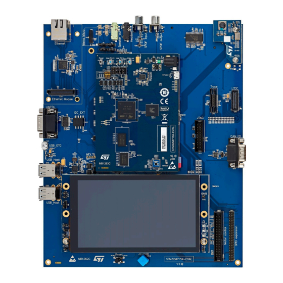
STM32MP157x-EV1, shown in
Figure 1
and
Figure
2, is used as the reference design for user application development,
although it is not considered as final application.
To expand the functionality of the
STM32MP157C-EV1
and
STM32MP157A-EV1
Evaluation boards, two GPIO expansion
connectors are also available for motor control and Raspberry Pi® shields.
An ST-LINK/V2-1 is integrated on the board, as embedded in-circuit debugger and programmer for the STM32 MPU and the
USB Virtual COM port bridge.
Figure 2.
STM32MP157x-EV1 bottom view
Figure 1.
STM32MP157x-EV1 top view
Pictures are not contractual.
UM2535 - Rev 1 - February 2019
www.st.com
For further information contact your local STMicroelectronics sales office.
Advertisement
Table of Contents

Related Manuals for ST STM32MP157 Series


Summary of Contents for ST STM32MP157 Series
-
Page 1: Figure 1. Stm32Mp157X-Ev1 Top View
Evaluation boards, two GPIO expansion connectors are also available for motor control and Raspberry Pi® shields. An ST-LINK/V2-1 is integrated on the board, as embedded in-circuit debugger and programmer for the STM32 MPU and the USB Virtual COM port bridge. -
Page 2: Features
– GPIO expansion connector (Raspberry Pi shields capability) – MEMS-microphone daughterboard expansion connector • On-board ST-LINK/V2-1 debugger/programmer with USB re-enumeration capability: Virtual COM port and debug port ® • STM32CubeMP1 and full mainline open-source Linux STM32 MPU OpenSTLinux distribution (such as STM32MP1Starter) software and examples ™... -
Page 3: Development Environment
The STM32 MPU OpenSTLinux distribution and STM32CubeMP1 base demonstration software is preloaded in ™ the microSD for easy demonstration of the device peripherals in standalone mode. The latest versions of the demonstration source code and associated documentation can be downloaded from www.st.com. UM2535 - Rev 1 page 3/55... -
Page 4: Ordering Information
Evaluation tools marked as “ES” or “E” are not yet qualified and therefore not ready to be used as reference design or in production. Any consequences deriving from such usage will not be at ST charge. In no event, ST will be liable for any customer usage of these engineering sample tools as reference design or in production. -
Page 5: Conventions
UM2535 Conventions Conventions Table 3 provides the conventions used for the ON and OFF settings in the present document. Table 3. ON/OFF convention Convention Definition Jumper JPx ON Jumper fitted Jumper JPx OFF Jumper not fitted Jumper JPx [1-2] Jumper should be fitted between Pin 1 and Pin 2 Solder bridge SBx ON SBx connections closed by 0 Ω... -
Page 6: Delivery Recommendations
LCD MB1230 daughterboard in MB1262/CN19 DSI connector, and screw, spacer and nut are in place Camera module MB1379 board in MB1262/CN7 connector, and screw, spacer and nut are in place For product information related with STM32MP157xAA3 microcontroller, visit www.st.com website. UM2535 - Rev 1... -
Page 7: Hardware Layout And Configuration
UM2535 Hardware layout and configuration Hardware layout and configuration The STM32MP157x-EV1 Evaluation board is designed around the STM32MP157xAA3 target microcontroller in LFBGA 448-pin package. Figure 3 illustrates the STM32MP157x-EV1 hardware block diagram. Figure 4 shows the location of main components on the Evaluation board. UM2535 - Rev 1 page 7/55... -
Page 8: Figure 3. Stm32Mp157X-Ev1 Hardware Block Diagram
DFSDM MEMS microphones SPDIF FDCAN connector FDCAN SPDIF TX/RX TX/RX RS232 DB9 SMARTCARD UART Smartcard connector connector ST-LINK / V2.1 JTAG/ I2C EXT connector USB micro-B GPIO 40 pins JTAG connector GPIOs Connector MICTOR-38 Motor Control Shared connector GPIOs connector... -
Page 9: Figure 4. Stm32Mp157X-Ev1 Board Overview
UM2535 Hardware layout and configuration Figure 4. STM32MP157x-EV1 board overview Note: Numbers in yellow refer to positions explained in Table Table 5, and Table UM2535 - Rev 1 page 9/55... -
Page 10: Table 4. Stm32Mp157X-Ev1 Overview
PMIC (STPMIC1A) 53 (LD3) User LED (green) 62 (LD6) ST-Link LED (bicolor) 54 (B3) User button (PA14) 63 (CN4) USB micro-B (ST-Link V2-1) 55 (LD5) User LED (blue) 64 (U4) STM32MP157xAA3 LFBGA448 56 (LD4) User LED (orange) 65 (U5) eMMC... -
Page 11: Power Supply Management
UM2535 Power supply management Power supply management 6.1.1 5 V power supply STM32MP157x-EV1 Evaluation board is designed to be powered from the 5 V DC power supply provided in the package. MB1263/LD1 Green LED turns on when this power supply is connected to the power jack MB1263/CN1. Figure 5. -
Page 12: Stpmic
Smart Card MB1263 µ-SD card MB1262 RS232 NAND JTAG & MFX IO Expander Trace connectors Q-SPI NOR MSv62137V1 6.1.3 STPMIC For general information concerning the STPMIC, please refer to STPMIC datasheet at the www.st.com website. UM2535 - Rev 1 page 12/55... -
Page 13: Clocks
JTAG/SWD connector MB1262/CN14 • ETM Trace Mictor-38 connector MB1262/U10 • Embedded ST-LINK/V2-1 The STM32MP157xAA3 also drives a sub system reset, SUB_NRST signal on PD10 IO, to the peripherals: USB Host Hub, MFX, Ethernet, and RGB_LTDC connector. User buttons and LEDs... -
Page 14: Boot Options
UM2535 Boot options Devices Purpose/IO JOY_RIGHT: Joystick right direction (MB1262/B1 pin6) MFX_IO3 JOY_UP: Joystick up direction (MB1262/B1 pin4) MFX_IO4 Boot options The STM32MP157x-EV1 board may boot from different sources as described in Table Table 9. HW configuration for the BOOT mode MB1263/SW1 Boot Mode BOOT2 BOOT1... -
Page 15: Embedded St-Link/V2-1
UM2535 Embedded ST-LINK/V2-1 Figure 7. STM32MP157x-EV1 boot related switch configuration Embedded ST-LINK/V2-1 The STLINK-V2.1 programming and debugging tool is integrated in the STM32MP157x-EV1 Evaluation board. The embedded STLINK-V2.1 supports JTAG, SWD and VCP for the target STM32 MPU devices. UM2535 - Rev 1... -
Page 16: Drivers
6.7.1 Drivers Before connecting STM32MP157x-EV1 to a Windows (XP, 7, 8 10) PC via USB, a driver for ST-LINK/V2-1 must be installed. It may be downloaded from www.st.com. In case the STM32MP157x-EV1 Evaluation board is connected to the PC before installing the driver, the Windows device manager may report some USB devices found on STM32MP157x-EV1as “Unknown”. -
Page 17: St-Link/V2-1 Firmware Upgrade
6.7.2 ST-LINK/V2-1 firmware upgrade For its own operation, ST-LINK/V2-1 employs a dedicated MCU with Flash memory. Its firmware determines ST- LINK/V2-1 functionality and performance. The firmware may evolve during the life span of STM32MP157x-EV1 to include new functionality, fix bugs or support new target microcontroller families. It is therefore recommended to keep ST-LINK/V2-1 firmware up to date. - Page 18 UM2535 ETM TRACE Mictor-38 connector Bridge Comment Setting PK1 may be used for the trace function TRACE_D4 SB40 PK1 is not connected to Trace PK1 may be used for LTDC_G6 PK2 may be used for the trace function TRACE_D5 SB39 PK2 is not connected to Trace PK2 may be used for LTDC_G7 PK5 may be used for the trace function TRACE_D6...
-
Page 19: Jtag Connector
UM2535 JTAG connector Figure 10. TRACE Mictor-38 connector: MB1262/U10 Table 12 describes the MICTOR-38 connector pinout for TRACE and JTAG signals. Table 12. TRACE MICTOR-38 connector pinout: MB1262/U10 Board function Board function TRACE_CLK Pulldown Pulldown NRST Pulldown TDO/SWO Pulldown TCK/SWCLK TRACE_D7 TMS/SWDIO TRACE_D6... -
Page 20: Ddr3L
Two 16-bit DDR3L NT5CC256M16ER-EK of 4 Gbytes are implemented in flyby topology in MB1263/U6 and U7 positions. They are connected to the dedicated DDR interface of STM32MP157xAA3. For detailed information concerning the DDR HW design implementation, please refer to the application note AN5122 available on the www.st.com website. 6.11... -
Page 21: Quad-Spi Nor Flash
UM2535 Quad-SPI NOR Flash 6.12.1 NAND IO interface Table 15 features the HW configuration for the NAND interface. Table 15. HW configuration for the Quad-SPI interface Configuration NAND_NWAIT connected to MB1262/U11 R/B# PD11 NAND_CLE connected to MB1262/U11 CLE PD12 NAND_ALE connected to MB1262/U11 ALE NAND_NCE connected to MB1262/U11 CE# NAND_NWE connected to MB1262/U11 WE# NAND_NOE connected to MB1262/U11 RE#... -
Page 22: Microsd Card
UM2535 microSD card 1. Minimum set of signals required by the boot ROM during dual-serial NOR boot in bold 6.14 microSD card The MB1263/CN9 slot for microSD card is routed to STM32MP157xAA3 SDMMC1 port. This SD card interface is compliance with SD Memory Card Specification Version 3.01, UHS-I, all operation modes up to SDR104 and DDR50. -
Page 23: Audio
UM2535 Audio Table 18 describes the SDCARD connector pinout MB1263/CN9. Table 18. SDCARD connector pinout MB1263/CN9 Board function DATA2_SD DATA3_SD CMD_SD VDD_SD CLK_SD DATA0_SD DATA1_SD SDCARD_DETECT active LOW 6.15 Audio A codec WM8994ECS/R connected to an SAI of STM32MP157xAA3 supports TDM feature of the SAI port. TDM feature offers to STM32MP157xAA3 the capability to stream stereo audio channels. -
Page 24: Digital Microphones
UM2535 Audio 6.15.2 Digital microphones MB1262/U1, U2, U3 and U4 are four MP34DT01TR MEMS digital omnidirectional microphones providing PDM (pulse density modulation) outputs. The implementation allows the beam forming. Those 4 digital microphones support two stereo inputs connected either to the audio Codec or, by default, connected on two DFSDM odd channels of STM32MP157xAA3: DFSDM_DATA1 and DFSDM_DATA3 synchronized on DFSDM_CKOUT. -
Page 25: Audio Speaker Out
UM2535 Audio Board function OUT_LEFT 6.15.4 Audio speaker out The codec stereo speaker output is connected to a green 3.5 mm Speaker_out jack MB1262/CN4. Figure 13. Audio jack connector MB1262/CN4 Table 22. Audio jack connector pinout MB1262/CN4 Board function OUT_RIGHT OUT_LEFT 6.15.5 SPDIF input and output... -
Page 26: Io Restriction To Other Features
UM2535 DSI LCD Figure 14. SPDIF input MB1262/CN1 and output MB1262/CN2 connectors 6.15.6 IO restriction to other features Due to the share of some IO of STM32MP157xAA3 by multiple peripherals, the following limitations apply in using the audio features: The SAI AUDIO CODEC must not be operated simultaneously with expansion connector MB1262/CN21. The MEMS DFSDM must not be operated simultaneously with DFSDM of EXT MEMS module MB1262/CN8. -
Page 27: Camera
UM2535 Camera Configuration DSI_D0N DSI_D0_N is used as MIPI-DSI data Lane 0 negative DSI_D1P DSI_D1_P is used as MIPI-DSI data Lane 1 positive DSI_D1N DSI_D1_N is used as MIPI-DSI data Lane 0 negative DSI_CKP DSI_CKP is used as clock Lane positive DSI_DKN DSI_DKN is used as clock Lane negative PD13... -
Page 28: Gbps Ethernet
UM2535 1 Gbps Ethernet Configuration MFX_O3 RSTI - Camera RESETB, active low MFX_O2 XSDN – Camera PWDN, active high 1. Available on the MB1262/CN7 connector, but not used in the MB1379 module 6.18 1 Gbps Ethernet The STM32MP157x-EV1 board provides a 1 Gbps Ethernet feature thanks to an external physical interface device (PHY), RTL8211EG-VB-CG. -
Page 29: Usb Otg Hs
UM2535 USB OTG HS Figure 15. Ethernet connector MB1262/CN3 Table 26. Ethernet connector pinout MB1262/CN3 Pin number Pin name Function TX1+ First Bidirectional pair to transmit and receive data TX1- TX2+ Second Bidirectional pair to transmit and receive data TX2- Common connected to GND Common connected to GND TX3+... -
Page 30: Usb Host
UM2535 USB host Configuration OTG_VBUS OTG_VBUS sensing USB_DP2 USB_DP2 USB_DM2 USB_DM2 Figure 16. USB OTG Type Micro-AB connector MB1262/CN16 Table 28. USB OTG Type Micro-AB connector pinout MB1262/CN16 Pin CN16 Pin name Signal name Function VBUS OTG VBUS VBUS supply and sensing USB_DM2 USB_DP2 VBUS... -
Page 31: Rs-232 Port
UM2535 RS-232 port Figure 17. Dual USB TYPE A connector MB1262/CN18 and CN20 Table 30. USB Host connector pinout MB1262/CN18 Pin CN18 Pin name Function VBUS VBUS Table 31. USB Host connector pinout MB1262/CN20 Pin CN20 Pin name Function VBUS VBUS 6.21 RS-232 port... -
Page 32: Rs-232 Interface
6.21.1 RS-232 interface The RS-232 transceiver MB1262/U12 supply is 3V3. The RS-232 interface is connected to the STM32MP157xAA3 UART4 that is shared exclusively with the USB micro-B/ST-LINK v2-1 VCP as described in Table Table 32. HW configuration for the RS-232 interface... -
Page 33: Io Restriction To Other Features
UM2535 FDCAN Board function Board function 6.21.2 IO restriction to other features The RS-232 must not be operated simultaneously with the STLINK-VCP. 6.22 FDCAN The STM32MP157x-EV1 board supports one FDCAN compliant with ISO-11898-1 version 2.0 part A, B. The MB1262/CN15 DB9 male connector is available as FDCAN interface. 6.22.1 Operating voltage A 5V/3v3 IO compliant high speed FDCAN transceiver is fitted between the MB1262/CN15 connector and the... -
Page 34: Smartcard
UM2535 Smartcard 6.23 Smartcard The STM32MP157x-EV1 board supports one Smartcard interface. The MB1262/CN23 Smartcard connector is used as card reader. 6.23.1 Smartcard interface A 3V3 Smartcard interface MB1262/U5 is used between the card reader connector MB1262/CN23 and the Smartcard controller port of STM32MP157xAA3. The Smartcard interface is connected for some IO to the STM32MP157xAA3 and for other IO to the MFX IO expander. -
Page 35: Adc/Dac
UM2535 ADC/DAC Board function U5 Smartcard interface pin I/O CARD DATA U5-11 U5-12 GND: CAR GND DETECT: CARD-Detect (LOW) U5-9 6.24 ADC/DAC The STM32MP157x-EV1 provides some on-board analog-to-digital converters ADC and digital-to-analog converters DAC: • 2x ADC/DAC • 2x Fast ADC •... -
Page 36: Limitations
UM2535 I2C_EXT connector Table 38. ADC/DAC connectors JP7/JP8/JP9/JP10/JP11 pinout Signal name Signal name ADC/DAC 6.24.4 Limitations Due to the share of some IO of STM32MP157xAA3 by multiple peripherals, the following limitations apply in using the PMOD Button features: The fast ADC ANA0/ANA1 and slow ADC PF12 may not be operated simultaneously with motor control function. -
Page 37: Mfx Mcu
UM2535 MFX MCU Table 40. I2C_EXT connector pinout MB1262/CN13 Signal name Signal name EXT_SDA EXT_SCL EXT_RST 6.26 MFX MCU The MFX: Multi-Function eXpander MCU is used as a GPIO expander, in position MB1262/U20. 6.26.1 MFX IO expander Supplied by 3V3. The communication interface between MFX and STM32MP157xAA3 is I2C bus, and an IRQOUT pin. -
Page 38: Motor Control
UM2535 Motor control Pin number Pin name Signal name Function GPIO15 6.27 Motor control The STM32MP157x-EV1 board supports both asynchronous and synchronous 3-phase brushless motor control via a 34-pin connector MB1262/CN22, which provides all required control and feedback signals, to and from motor power-driving board. -
Page 39: Limitations
UM2535 GPIO 40-pin expansion connector Motor Control connector CN22 STM32MP157xAA3 microcontroller Alternate Port Board configurations to Terminal Terminal name Function name enable Motor Control function NTC Bypass GPIO GPIO7 Close MB1262/SB19 GPIO12_TIM12_CH Dissipative Brake TIM12_CH1 Close MB1262/SB29 Close MB1262/SB70 Heatsink Temp. PF11 ADC_1_IN2 SAI_2_SD_B... -
Page 40: Table 44. Mb1262/Cn21 Connector Pinout
UM2535 GPIO 40-pin expansion connector Please note the pin1 position that is on the bottom right on MB1262/CN21. Table 44 describes the MB1262/CN21 connector pinout. Table 44. MB1262/CN21 connector pinout STM32 pin Board function Board function STM32 pin PA12 I2C5_SDA PA11 I2C5_SCL PI11... -
Page 41: Rgb Ltdc Connector
UM2535 RGB LTDC connector 6.29 RGB LTDC connector A 2x30-pin RGB LTDC connector is implemented on MB1262/CN11. Figure 26. MB1262/CN11 connector A 24-bit RGB interface, LCD control signals (INT, Backlight BL_CTRL, LCD_RESET, I2C), HDMI_CEC and SPDIF_TX are available as described in the connector pinout Section 6.29 Table 46. -
Page 42: Limitations
UM2535 RGB LTDC connector Board function Board function LCD_RESET (SUB_NRST) PD10 LTDC_G7 PA15 HDMI_CEC I2C2_SCL SPDIF_TX I2C2_SDA LCD_BL_CTRL LTDC_CLK PI14 6.29.1 Limitations LCD_INT, LCD_BL_CTRL are shared exclusively with the DSI. UM2535 - Rev 1 page 42/55... -
Page 43: A Appendix A Stm32Mp157X-Ev1 Jumper Summary
UM2535 Appendix A STM32MP157x-EV1 jumper summary Appendix A STM32MP157x-EV1 jumper summary Figure 27 summarize the jumper default setting of the STM32MP157x-EV1. Figure 27. Jumper default setting of the STM32MP157x-EV1 MB1262/JP2[2-3]: FITTED MB1262/JP1[2-3]: FITTED MB1262/JP3[1-2]:FITTED MB1262/JP4[1-2]:FITTED MB1263/JP1[-]: NOT FITTED MB1263/JP6[-], MB1263/JP7[-], MB1263/JP8[-], MB1263/JP9[-], MB1263/JP10[-],... -
Page 44: B Appendix B Stm32Mp157X-Ev1 Io Assignment
UM2535 Appendix B STM32MP157x-EV1 IO Assignment Appendix B STM32MP157x-EV1 IO Assignment Table 47. STM32MP157x-EV1 IO Assignment LFBGA448 ball IO Port Main function Motor Control connector WAKE_UP ETH_RX_CLK ETH_MDIO TIM2_CH4 Bus Voltage ADC1_IN18_DACOUT1 ADC1_IN19_DACOUT2 DCMI_PIXCLK Emergency Stop ETH_RX_DV SDMMC2_D4 SDMMC2_D5 PA10 OTG_ID PA11 I2C5_SCL... - Page 45 UM2535 Appendix B STM32MP157x-EV1 IO Assignment LFBGA448 ball IO Port Main function Motor Control connector ETH_RXD1 DSI_TE SDMMC1_D123DIR SDMMC1_D0 SDMMC1_D1 PC10 SDMMC1_D2 PC11 SDMMC1_D3 PC12 SDMMC1_CK PC13 PMIC_WAKEUP PC14 LSE_IN PC15 LSE_OUT NAND_D2 NAND_D3 SDMMC1_CMD SDMMC2_D123DIR NAND_NOE NAND_NWE NAND_NWAIT SDMMC3_D3 NAND_D13 NAND_D14 PD10...
- Page 46 UM2535 Appendix B STM32MP157x-EV1 IO Assignment LFBGA448 ball IO Port Main function Motor Control connector PE13 SAI2_FSB PE14 SAI2_MCLKB PE15 SDMMC3_D0 SDMMC3_CMD SDMMC1_D0DIR GPIO NTC Bypass SDMMC3_D1 SDMMC3_D2 AA11 QSPI_BK1_IO3 AA10 QSPI_BK1_IO2 AB10 QSPI_BK1_IO0 AB11 QSPI_BK1_IO1 PF10 QSPI_CLK PF11 SAI_2_SDB Heatsink Temp.
- Page 47 UM2535 Appendix B STM32MP157x-EV1 IO Assignment LFBGA448 ball IO Port Main function Motor Control connector I2C2_SDA TIM12_CH1 Dissipative Brake DCMI_D9 DCMI_HSYNC DCMI_D0 PH10 DCMI_D1 Encoder A PH11 DCMI_D2 Encoder B PH12 DCMI_D3 Encoder Index PH13 CAN_TX MC_UL PH14 DCMI_D4 MC_VL PH15 DCMI_D11 MC_WL...
- Page 48 UM2535 Appendix B STM32MP157x-EV1 IO Assignment LFBGA448 ball IO Port Main function Motor Control connector PJ13 LTDC_B1 PJ14 LTDC_B2 PJ15 LTDC_B3 LTDC_G5 LTDC_G6 TRACE_D4 LTDC_G7 TRACE_D5 LTDC_B4 LTDC_B5 LTDC_B6 TRACE_D6 LTDC_B7 TRACE_D7 LTDC_DE SPI1_SCK SPI1_MISO SPI1_MOSI SPI1_NSS I2C4_SCL I2C4_SDA SMARTCARD_CLK SMARTCARD _IO UM2535 - Rev 1 page 48/55...
-
Page 49: Revision History
UM2535 Revision history Table 48. Document revision history Date Version Changes 20-Feb-2019 Initial release. UM2535 - Rev 1 page 49/55... -
Page 50: Table Of Contents
ST-LINK/V2-1 firmware upgrade ........ - Page 51 UM2535 Contents 6.11 eMMC ............... 20 6.11.1 eMMC IO interface .
- Page 52 UM2535 Contents 6.23.1 Smartcard interface............34 6.24 ADC/DAC .
-
Page 53: List Of Tables
UM2535 List of tables List of tables Table 1. List of available products............. . . 4 Table 2. -
Page 54: List Of Figures
UM2535 List of figures List of figures Figure 1. STM32MP157x-EV1 top view ............1 Figure 2. - Page 55 ST’s terms and conditions of sale in place at the time of order acknowledgement. Purchasers are solely responsible for the choice, selection, and use of ST products and ST assumes no liability for application assistance or the design of Purchasers’...
Need help?
Do you have a question about the STM32MP157 Series and is the answer not in the manual?
Questions and answers