Table of Contents
Advertisement
Quick Links
UM1807
User manual
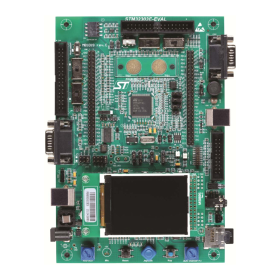
STM32303E-EVAL evaluation board
Introduction
The STM32303E-EVAL evaluation board has been designed as a complete demonstration
and development platform for STMicroelectronic's ARM
®
Cortex
®
-M4 core-based
STM32F303VET6 microcontrollers. It features two I2Cs, three SPIs, five USARTs, one
CAN, four 12-bit ADCs, two 12-bit DACs, internal 64-KByte Data SRAM, 16-KByte Program
SRAM and 512-KByte Flash, Touch sensing, USB FS, JTAG debugging support. This
evaluation board can be used as the reference design for user application development but
it is not considered as a final application.
The full range of hardware features on the board help you to evaluate all peripherals (USB
FS, USART, Audio DAC and ADC, TFT color LCD, IrDA, LDR, MicroSD card, Motor control
connectors, Humidity Sensor, High Brightness LED, CAN, IR, EEPROM, Touch Sensing
Buttons & Temperature Sensor... etc.) and to develop your own applications. Extension
headers make it possible to easily connect a daughter board or a wrapping board for your
specific application.
An ST-LINK/V2 is integrated on the board as an embedded in-circuit debugger and
programmer for the STM32 MCU.
Figure 1. STM32303E-EVAL evaluation board
October 2014
DocID026738 Rev 1
1/61
www.st.com
1
Arrow.com.
Downloaded from
Advertisement
Table of Contents

Related Manuals for ST STM32303E-EVAL


Summary of Contents for ST STM32303E-EVAL
-
Page 1: Figure 1. Stm32303E-Eval Evaluation Board
An ST-LINK/V2 is integrated on the board as an embedded in-circuit debugger and programmer for the STM32 MCU. Figure 1. STM32303E-EVAL evaluation board... -
Page 2: Table Of Contents
Contents UM1807 Contents Overview ..........6 Features . - Page 3 Schematics ..........41 Appendix A STM32303E-EVAL I/O assignment ......55 Appendix B Mechanical dimensions.
- Page 4 STM32303E-EVAL I/O assignment ........
- Page 5 STM32303E-EVAL RS232, RS485 and IrDA ........
-
Page 6: Overview
Overview UM1807 Overview Features • Four 5 V power supply options: Power jack, ST-LINK/V2 USB connector, User USB connector or daughter board • S Audio DAC, stereo audio jack which supports headset with microphone • 2-Gbyte or more SPI interface microSD card •... -
Page 7: Delivery Recommendations
CN1 connector (top left corner of the board). For all information concerning the version of the MCU used on the board, its specification and possible related limitations, please visit the ST web site to download the relevant data sheet and erratasheet. -
Page 8: Hardware Layout And Configuration
Hardware layout and configuration UM1807 Hardware layout and configuration The STM32303E-EVAL evaluation board has been designed around the STM32F303VET6 microcontroller (100-pin TQFP package). The hardware block diagram in Figure 2 illustrates the connection between the STM32F303VET6 microcontroller and its peripherals (color... -
Page 9: Figure 3. Stm32303E-Eval Evaluation Board Layout
UM1807 Hardware layout and configuration Figure 3. STM32303E-EVAL evaluation board layout DocID026738 Rev 1 9/61 Arrow.com. Arrow.com. Arrow.com. Arrow.com. Arrow.com. Arrow.com. Arrow.com. Arrow.com. Arrow.com. Downloaded from Downloaded from Downloaded from Downloaded from Downloaded from Downloaded from Downloaded from Downloaded from... -
Page 10: Development And Debug Support
The third-party debug tools are also supported by the JTAG/SWD connector, CN10, or the ETM Trace connector, CN9. A specific driver needs to be installed on your PC for communication with embedded ST- LINK/V2.The install shield called ST-LINK_V2_USBdriver.exe is available at www.st.com/stlinkv2. -
Page 11: Power Supply
(PSU) on silkscreen of JP14). The external power supply is not provided with the board. • 5 V DC power with 500 mA limitation from CN5, the USB type B connector of ST- LINK/V2 (USB 5 V power source on silkscreen of JP14 ( STlk)). •... -
Page 12: Table 3. Power Mode Related Jumpers
2.1 V to 3.5 V considering some peripheral component specifications. LED LD8 is lit when the STM32303E-EVAL evaluation board is correctly powered by 5 V. A total of three power modes are supported on the board, and can be configured by setting... -
Page 13: Clock Source
CN12 Temperature sensor I2C2 2.25V Note: When an external DC 5V power supply is used to power the STM32303E-EVAL, it needs to be connected to CN14 after verifying the correct polarity as explained in Section 3.13. Caution: RISK OF EXPLOSION IF THE BATTERY IS REPLACED BY AN INCORRECT TYPE. -
Page 14: Reset Source
PF1 is connected to the extension connector CN7 when SB15 is closed. In such a case, R205 must be removed. Reset source The reset signal of the STM32303E-EVAL evaluation board is low active and the reset sources include: • Reset button (B1) •... -
Page 15: Audio
Default Setting: Not fitted Audio The STM32303E-EVAL evaluation board supports stereo audio play and microphone recording by an external headset connected on audio jack CN11. An audio DAC CS42L52 is connected to the I2S port of the STM32F303VET6 microcontroller. The microphone on headset or microphone which is reserved on board (U26, default unmounted) are connected to ADC of CS42L52. -
Page 16: Usb
The I2C address of CS42L52 is 0b1001010, and that of External PLL CS2200 is 0b1001110. The STM32303E-EVAL evaluation board supports USB2.0 compliant full speed communication via a USB type B connector (CN12). The evaluation board can be powered by this USB connection at 5 V DC with 500 mA current. -
Page 17: Touch-Sensing Buttons
The bus termination is enabled when solder bridge SB16 is closed. SB16 Default setting: Not fitted. Touch-sensing buttons The STM32303E-EVAL evaluation board supports two touch-sensing buttons based on the charge transfer technology. Table 12. Touch-sensing button related solder bridges Solder bridge Description PD13 is connected to the touch button when SB6 is open. -
Page 18: Microsd Card
Hardware layout and configuration UM1807 Table 12. Touch-sensing button related solder bridges (continued) Solder bridge Description PD15 is connected to the touch button when SB7 is open. (Default setting) PD15 is connected to the extension connector CN7 when SB7 is closed. In such a case, R102 must be removed to avoid disturbance due to the touch button. -
Page 19: Eeprom
2.16 High brightness LED An amber high brightness LED and its power control circuits are on the STM32303E-EVAL board. The brightness can be adjusted by the PWM signal from STM32F303VET6 through PE13. The current on the LED can be monitored by the STM32F303 thanks to the voltage measured on PD14, which corresponds to current through R261 (10 ohm). -
Page 20: Humidity Sensor
Hardware layout and configuration UM1807 2.17 Humidity sensor A humidity sensor, HS1101LF, is on the STM32303E-EVAL board. The charge control signal is connected to the timer in STM32F303VET6 through PC8, and the measured result of HS1101LF is connected with PB0. Note: Please keep VDDA =V DDIO during the measurement. -
Page 21: Display And Input Devices
UM1807 Hardware layout and configuration Table 16. Temperature sensor related jumpers Jumper Description An SMB signal connects to the temperature sensor event signal when JP1 is closed. Default setting: Not fitted The I2C address of the temperature sensor is 0b1001000. STTS751 will work properly when VDD >... -
Page 22: Motor Control
2.21 Motor control The STM32303E-EVAL evaluation board supports 2 inductor motor controls via 34-pin connectors CN2 and CN4, which provide all required control and feedback signals to and from the motor power-driving board. Available signals on these connectors include emergency stop, motor speed, 3-phase motor current, bus voltage, heatsink temperature coming from the motor driving board and 6 channels of PWM control signal going to the motor driving circuit. -
Page 23: Table 18. Motor Control Related Jumpers
UM1807 Hardware layout and configuration Mount odd number resistors from R1 to R57 (R1, R3….R55, R57) except R11 which is mounted by default with a 0-ohm resistor. The resistor positions on the PCB board are shown in Figure Figure 6. Resistor positions on the PCB board: odd number mounting Table 18. -
Page 24: Table 19. Motor Control Related Switches And Solder Bridges In Oam Position
Hardware layout and configuration UM1807 Table 19. Motor control related switches and solder bridges in OAM position OAM position Other conditions Description R113, R116 mounted MC1_CurrentA+ connect to OPAMP1_IN+(PA1) SB2 open MC1_CurrentB+ connect to OPAMP2_IN1+(PA7) R113, R116 unmounted MC1_CurrentB+ connect to OPAMP1_IN+(PA1) SB2 closed OAM1 3SA position... -
Page 25: Table 20. Motor Control Related Switches And Solder Bridges In Pgm Position
UM1807 Hardware layout and configuration Table 20. Motor control related switches and solder bridges in PGM position PGM position Other conditions Description PGM1 OPAMP1_IN+,OPAMP2_IN1+, OPAMP2_IN2+ pull-up source connect to +3.3V power PG3SA position OPAMP1_IN+, OPAMP2_IN1+, OPAMP2_IN2+ pull-up source connect to DAC_OUT1(PA4) PGM1 PG3SA position OPAMP1_IN+, OPAMP2_IN1+ pull-up source... - Page 26 Hardware layout and configuration UM1807 - in case of 3shunt, a jumper must be placed from PD14 to PB14 across the extension connector; - be aware that heatsink temperature measurement must be disabled on motor2; - be aware that MC SDK LCD UI must be disabled (conflict on SPI2 MISO). 26/61 DocID026738 Rev 1 Arrow.com.
-
Page 27: Connectors
UM1807 Connectors Connectors RF EEPROM daughter board connector (CN1) Figure 7. RF EEPROM daughter board connector (CN1) 1. Front view Table 21. RF EEPROM daughter board connector (CN1) Pin number Description SDA(PA10) SCL(PF6) RESET(PE14) DocID026738 Rev 1 27/61 Arrow.com. Arrow.com. Arrow.com. -
Page 28: Motor Control Connector (Cn2)
Connectors UM1807 Motor control connector (CN2) Figure 8. Motor control 1 connector (CN2) 1. Top view Table 22. Motor control 1 connector (CN2) Pin of Pin number Pin number Pin of Description Description STM32F303VET6 (odd) of CN2 (even) of CN2 STM32F303VET6 Emergency PE15... -
Page 29: Can D-Type 9-Pin Male Connector (Cn3)
UM1807 Connectors CAN D-type 9-pin male connector (CN3) Figure 9. CAN D-type 9-pin male connector (CN3) 1. Front view Table 23. CAN D-type 9-pin male connector (CN3) Pin number Description 1, 4, 8, 9 CANL 3, 5, 6 CANH DocID026738 Rev 1 29/61 Arrow.com. -
Page 30: Motor Control Connector (Cn4)
Connectors UM1807 Motor control connector (CN4) Figure 10. Motor control 2 connector (CN4) 1. Top view Table 24. Motor control 2 connector (CN4) Pin of Pin number Pin number Pin of Description Description STM32F303VET6 (odd) of CN4 (even) of CN4 STM32F303VET6 Emergency STOP PWM-1H... -
Page 31: St-Link/V2 Usb Type-B Connector (Cn5)
UM1807 Connectors ST-LINK/V2 USB type-B connector (CN5) The USB connector, CN5, is used to connect the embedded ST-LINK/V2 to the PC for board debugging. Figure 11. USB type-B connector (CN5) 1. Front view Table 25. USB type-B connector (CN5) Pin number... -
Page 32: Daughter Board Extension Connectors (Cn6 And Cn7)
Daughter board extension connectors (CN6 and CN7) Two 52-pin male headers, CN6 and CN7, can be used to connect with the daughter board or standard wrapping board to the STM32303E-EVAL evaluation board. All GPIOs are available on them. The space between these two connectors and the position of the power, GND and RESET pins are defined as a standard which allows developing common daughter boards for several evaluation boards. - Page 33 UM1807 Connectors Table 26. Daughter board extension connector (CN6) (continued) How to disconnect with function block on Description Alternative function STM32303E-EVAL board SPI2_SCK Remove R303 PF10 MC2_DissipativeBrake Disconnect CN4 OPAMP4_IN1+/ PB11 Remove R35, R137, Close SB11 SHIELD_CT MC2_PWM_1H/ Remove R47, R48...
-
Page 34: Table 27. Daughter Board Extension Connector (Cn7)
Connectors UM1807 Table 27. Daughter board extension connector (CN7) How to disconnect with function block Description Alternative function on STM32303E-EVAL board PD14 OPAMP2_IN2+ / LED_FB Remove R45, R46 PD11 MC2_Ain+_ADC34 Remove R92 MC1_MC2_PFC_Vac Remove R80, R146, C7, C26 PC13 JOY_SEL... - Page 35 UM1807 Connectors Table 27. Daughter board extension connector (CN7) (continued) How to disconnect with function block Description Alternative function on STM32303E-EVAL board PE14 ACP_RESET/SPI2_DIR Remove R136, R140 PE13 MC1_PWM_3H / LED_DRV Remove R31, R32 PE11 MC1_PWM_2H / LED4 Remove R29, R30...
-
Page 36: Rs232 And Rs485 Connector (Cn8)
Connectors UM1807 RS232 and RS485 connector (CN8) Figure 12. RS232 and RS485 connector 1. Front view Table 28. RS232 and RS485 connector (CN8) with ISP support Pin number Description RS232_RX (PE1) RS232_TX (PC4) RS485_A Bootloader_BOOT0 Bootloader_RESET RS485_B 36/61 DocID026738 Rev 1 Arrow.com. -
Page 37: Etm Trace Debugging Connector (Cn9)
UM1807 Connectors ETM Trace debugging connector (CN9) Figure 13. ETM Trace debugging connector (CN9) 1. Top view Table 29. ETM trace debugging connector (CN9) Pin number (odd) Description Pin number (even) Description VDD power TMS/PA13 TCK/PA14 TDO/PB3 TDI/PA15 RESET# TraceCLK/PE2 TraceD0/PE3 or SWO/PB3 TraceD1/PE4 or nTRST/PB4 TraceD2/PE5... -
Page 38: Jtag/Swd Connector (Cn10)
PA13 PA14 RTCK RESET# DBGRQ DBGACK 3.10 Audio jack (CN11) A 3.5 mm stereo audio jack, CN11, is available on the STM32303E-EVAL board to support the headset (headphone and microphone integrated). 38/61 DocID026738 Rev 1 Arrow.com. Arrow.com. Arrow.com. Arrow.com. Arrow.com. -
Page 39: User Usb Type-B Connector (Cn12)
It is not populated by default and not for an end user. 3.13 Power connector (CN14) The STM32303E-EVAL evaluation board can be powered from a 5 V DC power supply via the external power supply jack (CN14) shown in Figure 16. -
Page 40: Tft Lcd Connector (Cn15)
Connectors UM1807 3.14 TFT LCD connector (CN15) A TFT color LCD board is mounted on the CN15 connector. More details in Section 2.20. 3.15 MicroSD connector (CN16) Figure 17. MicroSD connector (CN16) 1. Top view Table 32. MicroSD connector (CN16) Pin number Description MicroSDcard_CS (PE15) -
Page 41: Schematics
UM1807 Schematics DocID026738 Rev 1 41/61 Arrow.com. Arrow.com. Arrow.com. Arrow.com. Arrow.com. Arrow.com. Arrow.com. Arrow.com. Arrow.com. Arrow.com. Arrow.com. Arrow.com. Arrow.com. Arrow.com. Arrow.com. Arrow.com. Arrow.com. Arrow.com. Arrow.com. Arrow.com. Arrow.com. Arrow.com. Arrow.com. Arrow.com. Arrow.com. Arrow.com. Arrow.com. Arrow.com. Arrow.com. Arrow.com. Arrow.com. Arrow.com. Arrow.com. Arrow.com. Arrow.com. -
Page 42: Figure 19. Stm32303E-Eval Mcu
Schematics UM1807 42/61 DocID026738 Rev 1 Arrow.com. Arrow.com. Arrow.com. Arrow.com. Arrow.com. Arrow.com. Arrow.com. Arrow.com. Arrow.com. Arrow.com. Arrow.com. Arrow.com. Arrow.com. Arrow.com. Arrow.com. Arrow.com. Arrow.com. Arrow.com. Arrow.com. Arrow.com. Arrow.com. Arrow.com. Arrow.com. Arrow.com. Arrow.com. Arrow.com. Arrow.com. Arrow.com. Arrow.com. Arrow.com. Arrow.com. Arrow.com. Arrow.com. Arrow.com. Arrow.com. -
Page 43: Figure 20. Stm32303E-Eval Power
UM1807 Schematics DocID026738 Rev 1 43/61 Arrow.com. Arrow.com. Arrow.com. Arrow.com. Arrow.com. Arrow.com. Arrow.com. Arrow.com. Arrow.com. Arrow.com. Arrow.com. Arrow.com. Arrow.com. Arrow.com. Arrow.com. Arrow.com. Arrow.com. Arrow.com. Arrow.com. Arrow.com. Arrow.com. Arrow.com. Arrow.com. Arrow.com. Arrow.com. Arrow.com. Arrow.com. Arrow.com. Arrow.com. Arrow.com. Arrow.com. Arrow.com. Arrow.com. Arrow.com. Arrow.com. -
Page 44: Figure 21. Stm32303E-Eval Rs232, Rs485 And Irda
Schematics UM1807 44/61 DocID026738 Rev 1 Arrow.com. Arrow.com. Arrow.com. Arrow.com. Arrow.com. Arrow.com. Arrow.com. Arrow.com. Arrow.com. Arrow.com. Arrow.com. Arrow.com. Arrow.com. Arrow.com. Arrow.com. Arrow.com. Arrow.com. Arrow.com. Arrow.com. Arrow.com. Arrow.com. Arrow.com. Arrow.com. Arrow.com. Arrow.com. Arrow.com. Arrow.com. Arrow.com. Arrow.com. Arrow.com. Arrow.com. Arrow.com. Arrow.com. Arrow.com. Arrow.com. -
Page 45: Figure 22. Stm32303E-Eval Audio
UM1807 Schematics DocID026738 Rev 1 45/61 Arrow.com. Arrow.com. Arrow.com. Arrow.com. Arrow.com. Arrow.com. Arrow.com. Arrow.com. Arrow.com. Arrow.com. Arrow.com. Arrow.com. Arrow.com. Arrow.com. Arrow.com. Arrow.com. Arrow.com. Arrow.com. Arrow.com. Arrow.com. Arrow.com. Arrow.com. Arrow.com. Arrow.com. Arrow.com. Arrow.com. Arrow.com. Arrow.com. Arrow.com. Arrow.com. Arrow.com. Arrow.com. Arrow.com. Arrow.com. Arrow.com. -
Page 46: Figure 23. Stm32303E-Eval Motor Control
Schematics UM1807 46/61 DocID026738 Rev 1 Arrow.com. Arrow.com. Arrow.com. Arrow.com. Arrow.com. Arrow.com. Arrow.com. Arrow.com. Arrow.com. Arrow.com. Arrow.com. Arrow.com. Arrow.com. Arrow.com. Arrow.com. Arrow.com. Arrow.com. Arrow.com. Arrow.com. Arrow.com. Arrow.com. Arrow.com. Arrow.com. Arrow.com. Arrow.com. Arrow.com. Arrow.com. Arrow.com. Arrow.com. Arrow.com. Arrow.com. Arrow.com. Arrow.com. Arrow.com. Arrow.com. -
Page 47: Figure 24. Stm32303E-Eval Can, Ir, High-Brightness Led And Humidity Sensor
UM1807 Schematics DocID026738 Rev 1 47/61 Arrow.com. Arrow.com. Arrow.com. Arrow.com. Arrow.com. Arrow.com. Arrow.com. Arrow.com. Arrow.com. Arrow.com. Arrow.com. Arrow.com. Arrow.com. Arrow.com. Arrow.com. Arrow.com. Arrow.com. Arrow.com. Arrow.com. Arrow.com. Arrow.com. Arrow.com. Arrow.com. Arrow.com. Arrow.com. Arrow.com. Arrow.com. Arrow.com. Arrow.com. Arrow.com. Arrow.com. Arrow.com. Arrow.com. Arrow.com. Arrow.com. -
Page 48: Figure 25. Stm32303E-Eval Lcd, Sdcard And Flash
Schematics UM1807 48/61 DocID026738 Rev 1 Arrow.com. Arrow.com. Arrow.com. Arrow.com. Arrow.com. Arrow.com. Arrow.com. Arrow.com. Arrow.com. Arrow.com. Arrow.com. Arrow.com. Arrow.com. Arrow.com. Arrow.com. Arrow.com. Arrow.com. Arrow.com. Arrow.com. Arrow.com. Arrow.com. Arrow.com. Arrow.com. Arrow.com. Arrow.com. Arrow.com. Arrow.com. Arrow.com. Arrow.com. Arrow.com. Arrow.com. Arrow.com. Arrow.com. Arrow.com. Arrow.com. -
Page 49: Figure 26. Stm32303E-Eval I2C Peripherals
UM1807 Schematics DocID026738 Rev 1 49/61 Arrow.com. Arrow.com. Arrow.com. Arrow.com. Arrow.com. Arrow.com. Arrow.com. Arrow.com. Arrow.com. Arrow.com. Arrow.com. Arrow.com. Arrow.com. Arrow.com. Arrow.com. Arrow.com. Arrow.com. Arrow.com. Arrow.com. Arrow.com. Arrow.com. Arrow.com. Arrow.com. Arrow.com. Arrow.com. Arrow.com. Arrow.com. Arrow.com. Arrow.com. Arrow.com. Arrow.com. Arrow.com. Arrow.com. Arrow.com. Arrow.com. - Page 50 Schematics UM1807 50/61 DocID026738 Rev 1 Arrow.com. Arrow.com. Arrow.com. Arrow.com. Arrow.com. Arrow.com. Arrow.com. Arrow.com. Arrow.com. Arrow.com. Arrow.com. Arrow.com. Arrow.com. Arrow.com. Arrow.com. Arrow.com. Arrow.com. Arrow.com. Arrow.com. Arrow.com. Arrow.com. Arrow.com. Arrow.com. Arrow.com. Arrow.com. Arrow.com. Arrow.com. Arrow.com. Arrow.com. Arrow.com. Arrow.com. Arrow.com. Arrow.com. Arrow.com. Arrow.com.
-
Page 51: Figure 28. Stm32303E-Eval St-Link (Jtag Only)
UM1807 Schematics DocID026738 Rev 1 51/61 Arrow.com. Arrow.com. Arrow.com. Arrow.com. Arrow.com. Arrow.com. Arrow.com. Arrow.com. Arrow.com. Arrow.com. Arrow.com. Arrow.com. Arrow.com. Arrow.com. Arrow.com. Arrow.com. Arrow.com. Arrow.com. Arrow.com. Arrow.com. Arrow.com. Arrow.com. Arrow.com. Arrow.com. Arrow.com. Arrow.com. Arrow.com. Arrow.com. Arrow.com. Arrow.com. Arrow.com. Arrow.com. Arrow.com. Arrow.com. Arrow.com. -
Page 52: Figure 29. Stm32303E-Eval Jtag And Trace
Schematics UM1807 52/61 DocID026738 Rev 1 Arrow.com. Arrow.com. Arrow.com. Arrow.com. Arrow.com. Arrow.com. Arrow.com. Arrow.com. Arrow.com. Arrow.com. Arrow.com. Arrow.com. Arrow.com. Arrow.com. Arrow.com. Arrow.com. Arrow.com. Arrow.com. Arrow.com. Arrow.com. Arrow.com. Arrow.com. Arrow.com. Arrow.com. Arrow.com. Arrow.com. Arrow.com. Arrow.com. Arrow.com. Arrow.com. Arrow.com. Arrow.com. Arrow.com. Arrow.com. Arrow.com. -
Page 53: Figure 30. Tm32330C-Eval Touch Sensing
UM1807 Schematics DocID026738 Rev 1 53/61 Arrow.com. Arrow.com. Arrow.com. Arrow.com. Arrow.com. Arrow.com. Arrow.com. Arrow.com. Arrow.com. Arrow.com. Arrow.com. Arrow.com. Arrow.com. Arrow.com. Arrow.com. Arrow.com. Arrow.com. Arrow.com. Arrow.com. Arrow.com. Arrow.com. Arrow.com. Arrow.com. Arrow.com. Arrow.com. Arrow.com. Arrow.com. Arrow.com. Arrow.com. Arrow.com. Arrow.com. Arrow.com. Arrow.com. Arrow.com. Arrow.com. -
Page 54: Figure 31. Color Lcd Daughter Board (Mb895)
Schematics UM1807 54/61 DocID026738 Rev 1 Arrow.com. Arrow.com. Arrow.com. Arrow.com. Arrow.com. Arrow.com. Arrow.com. Arrow.com. Arrow.com. Arrow.com. Arrow.com. Arrow.com. Arrow.com. Arrow.com. Arrow.com. Arrow.com. Arrow.com. Arrow.com. Arrow.com. Arrow.com. Arrow.com. Arrow.com. Arrow.com. Arrow.com. Arrow.com. Arrow.com. Arrow.com. Arrow.com. Arrow.com. Arrow.com. Arrow.com. Arrow.com. Arrow.com. Arrow.com. Arrow.com. -
Page 55: Appendix A Stm32303E-Eval I/O Assignment
UM1807 STM32303E-EVAL I/O assignment Appendix A STM32303E-EVAL I/O assignment Table 33. STM32303E-EVAL I/O assignment STM32303E-EVAL double motor STM32303E-EVAL general Pin no. Pin name control I/O assignment purpose features I/O assignment MC1_MC2_PFC_Sync TRACECK MC1_MC2_PFC_PWM TRACED0 MC1_ICL-shut-out TRACED1 MC1_Dissipative_brake TRACED2 PE6 - WKUP3... - Page 56 STM32303E-EVAL I/O assignment UM1807 Table 33. STM32303E-EVAL I/O assignment (continued) STM32303E-EVAL double motor STM32303E-EVAL general Pin no. Pin name control I/O assignment purpose features I/O assignment OPAMP2_OUT OPAMP2_IN1+ USART1_TX OPAMP2_IN- OPAMP3_IN+ Humidity_input OPAMP3_OUT OPAMP3_IN- 1.8V POR Joy_up MC1_PWM_1L LED1 MC1_PWM_1H...
- Page 57 UM1807 STM32303E-EVAL I/O assignment Table 33. STM32303E-EVAL I/O assignment (continued) STM32303E-EVAL double motor STM32303E-EVAL general Pin no. Pin name control I/O assignment purpose features I/O assignment MC2_PWM_3H Humidity_output I2S_CKIN I2C2_SMBAl / Audio_MCO IR_IN / I2S_MCK PA10 I2C2_SDA PA11 USBDM PA12...
- Page 58 STM32303E-EVAL I/O assignment UM1807 Table 33. STM32303E-EVAL I/O assignment (continued) STM32303E-EVAL double motor STM32303E-EVAL general Pin no. Pin name control I/O assignment purpose features I/O assignment VSSA - VSS1 VDDA - VDD1 58/61 DocID026738 Rev 1 Arrow.com. Arrow.com. Arrow.com. Arrow.com.
-
Page 59: Appendix B Mechanical Dimensions
UM1807 Mechanical dimensions Appendix B Mechanical dimensions Figure 32. Mechanical dimensions Table 34. Mechanical dimensions Symbol Size (mm) Symbol Size (mm) Symbol Size (mm) 68.58 77.44 25.4 2.54 111.76 2.54 7.62 25.4 5.715 19.05 21.62 118.11 23.81 172.72 DocID026738 Rev 1 59/61 Arrow.com. -
Page 60: Revision History
Revision history UM1807 Revision history Table 35. Document revision history Date Revision Changes 31-Oct-2014 Initial release. 60/61 DocID026738 Rev 1 Arrow.com. Arrow.com. Arrow.com. Arrow.com. Arrow.com. Arrow.com. Arrow.com. Arrow.com. Arrow.com. Arrow.com. Arrow.com. Arrow.com. Arrow.com. Arrow.com. Arrow.com. Arrow.com. Arrow.com. Arrow.com. Arrow.com. Arrow.com. Arrow.com. - Page 61 ST products and/or to this document at any time without notice. Purchasers should obtain the latest relevant information on ST products before placing orders. ST products are sold pursuant to ST’s terms and conditions of sale in place at the time of order acknowledgement.
Need help?
Do you have a question about the STM32303E-EVAL and is the answer not in the manual?
Questions and answers