ST STM32U5 User Manual
Nucleo-144 board mb1549
Hide thumbs
Also See for STM32U5:
- User manual (49 pages) ,
- Getting started (47 pages) ,
- Application note (56 pages)
Table of Contents
Advertisement
UM2861
User manual
STM32U5 Nucleo-144 board (MB1549)
Introduction
The STM32U5 Nucleo-144 board based on the MB1549 reference board (order codes
NUCLEO-U575ZI-Q
and
NUCLEO-
U5A5ZJ-Q) provides an affordable and flexible way for users to try out new concepts and build prototypes by choosing from the
various combinations of performance and power‑consumption features, provided by the STM32U5 microcontroller.
®
The ST Zio connector, which extends the ARDUINO
Uno V3 connectivity, and the ST morpho headers provide easy expansion
of the functionality of the STM32 Nucleo open development platform with a wide choice of specialized shields.
The STM32U5 Nucleo-144 board does not require any separate probe as it integrates the STLINK-V3E debugger/programmer.
The STM32U5 Nucleo-144 board comes with the STM32 comprehensive free software libraries and examples available with the
STM32CubeU5
MCU Package.
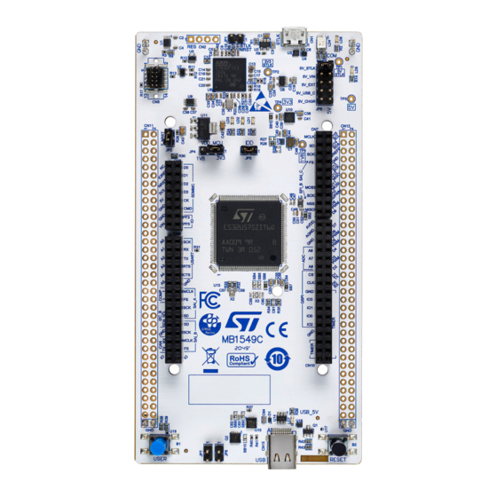
Figure 1.
STM32U5 Nucleo-144 board
Picture is not contractual.
UM2861 - Rev 5 - February 2023
www.st.com
For further information contact your local STMicroelectronics sales office.
Advertisement
Table of Contents


Need help?
Do you have a question about the STM32U5 and is the answer not in the manual?
Questions and answers