Table of Contents
Advertisement
Introduction
STM32Cube is an STMicroelectronics original initiative to make developers' lives easier by
reducing development effort, time and cost. STM32Cube covers the whole STM32 portfolio.
The STM32CubeH7 demonstration platform complements STM32Cube as a firmware
package that offers a full set of software components based on a modular architecture,
separately reusable in standalone applications. The STM32CubeH7 demonstration kernel
manages all these modules, allowing dynamic addition of new modules, and access to
common resources (storage, graphical components and widgets, memory management,
real-time operating system).
The STM32CubeH7 demonstration platform is built around the powerful STemWin graphical
library and the FreeRTOS™ real-time operating system, and uses almost the whole STM32
capability to offer a large scope of usage based on the STM32Cube HAL BSP and several
middleware components.
The architecture uses the STM32CubeH7 demonstration core to make an independent
central component that is usable with several RTOSs and third party firmware libraries
through dedicated abstraction layers inserted between the STM32CubeH7 demonstration
core and the associated modules and libraries.
The STM32CubeH7 demonstration supports STM32H7 Series devices and runs on
STM32H743I-EVAL, STM32H745I-DISCO, STM32H747I EVAL, STM32H747I DISCO and
STM32H747I DISC1 boards.
Pictures are not contractual.
June 2019
STM32CubeH7 demonstration platform
UM2222 Rev 2
UM2222
User manual
www.st.com
1/76
1
Advertisement
Table of Contents

Subscribe to Our Youtube Channel
Related Manuals for ST STM32CubeH7


Summary of Contents for ST STM32CubeH7
- Page 1 (storage, graphical components and widgets, memory management, real-time operating system). The STM32CubeH7 demonstration platform is built around the powerful STemWin graphical library and the FreeRTOS™ real-time operating system, and uses almost the whole STM32 capability to offer a large scope of usage based on the STM32Cube HAL BSP and several middleware components.
-
Page 2: Table Of Contents
Contents UM2222 Contents STM32Cube overview ........8 Global architecture . - Page 3 UM2222 Contents Performance ..........31 CPU cache .
- Page 4 Contents UM2222 8.3.1 Overview ..........60 8.3.2 Video player module (only H743I-EVAL) .
- Page 5 UM2222 List of tables List of tables Table 1. File system interface functions ..........18 Table 2.
- Page 6 STM32CubeH7 demonstration architecture ........
- Page 7 UM2222 List of figures Figure 49. TouchGFX - Light effect module ..........56 Figure 50.
-
Page 8: Stm32Cube Overview
C initialization code using graphical wizards • STM32Cube MCU & MPU Packages, comprehensive embedded-software platforms specific to each microcontroller and microprocessor series (such as STM32CubeH7 for the STM32H7 Series), which include: – STM32Cube hardware abstraction layer (HAL), ensuring maximized portability ®(a) -
Page 9: Global Architecture
Global architecture Global architecture The STM32CubeH7 demonstration is composed of a central kernel based on a set of firmware and hardware services offered by the STM32Cube middleware, several Evaluation and Discovery boards, and a set of modules mounted on the kernel and built in a modular architecture. -
Page 10: Kernel Description
Kernel description UM2222 Kernel description Overview The role of the demonstration kernel is mainly to provide a generic platform that controls and monitors all the application processes. The kernel provides a set of friendly user APIs and services, allowing the user modules to benefit from all the hardware and firmware resources. -
Page 11: Kernel Initialization
UM2222 Kernel description Kernel initialization The first task of the kernel is to initialize the hardware and firmware resources to make them available to its internal processes and the modules around it. The kernel starts by initializing the HAL system clocks, and then the hardware resources needed by the middleware components: •... -
Page 12: Kernel Processes And Tasks
Kernel description UM2222 Kernel processes and tasks The kernel is composed of a main task and software timer scheduled by FreeRTOS through the CMSIS-OS wrapping layer: • GUI thread: this task initializes the demonstration main menu and then handles the graphical background task when requested by the STemWin. -
Page 13: Kernel Graphical Aspect
UM2222 Kernel description Kernel graphical aspect The graphical aspect of the STM32Cube demonstration is divided into three main graphical components listed below: • At the board reset, the splash screen appears for a few seconds. The splash screen can be skipped by a simple click on the screen, to launch the main menu of the three demonstrations. -
Page 14: Kernel Menu Management
Kernel description UM2222 Kernel menu management Note: Important - This user manual describes all the demonstration modules. STemWin and TouchGFX modules are detailed as the source code is provided. The main demonstration menu is initialized and launched by the GUI thread. Before the initialization of the menu, the following actions are performed: •... -
Page 15: Module Manager
UM2222 Kernel description A module is launched with a simple click on the associated icon by calling to the startup function in the module structure. This is performed when a WM_NOTIFICATION_RELEASED message arrives to the desktop callback with ID_ICONVIEW_MENU. Module manager The kernel manages the modules. - Page 16 Kernel description UM2222 Each module provides the following functionalities and properties: • Icon and graphical component structure • Method to startup the module • Method to close down safely the module (such as Hot unplug for MS flash disk) • Method to manage low-power modes (optional) •...
-
Page 17: Backup And Settings Configuration
UM2222 Kernel description Backup and settings configuration The STM32Cube demonstration saves the kernel and module settings using the following method: • Using the RTC backup register (32-bit data width): the data to save must be a 32-bit data and can be defined as a bit field structure. •... -
Page 18: Table 1. File System Interface Functions
Kernel description UM2222 Table 1. File system interface functions Function Description disk_initialize Initialize disk drive disk_read Interface function for a logical page read disk_write Interface function for a logical page write disk_status Interface function for testing if unit is ready disk_ioctl Control device dependent features f_mount... -
Page 19: Adding Binary Demonstration
The user can load a specific demonstration as a binary in a specific memory address. The specific demonstration is launched during the run-time of the native ST demonstration. The main demonstration (ST demonstration) jumps to the specific demonstration address. From the specific demonstration, the user can go back to the main demonstration by doing a hardware reset. - Page 20 A is saved in the backup SRAM and a reset is performed. During the next start of the ST demonstration, the signature is checked. If the result is A, the PC jumps to the specific demonstration memory location and the specific demonstration starts.
-
Page 21: Demonstration Repository
UM2222 Kernel description 3.10 Demonstration repository The STM32Cube is a component in the STM32Cube package. Figure 11 shows the demonstration folder organization. Figure 11. Demonstration folder structure In the STM32Cube package, the demonstration sources are located in the Demonstration folder of each supported board. The sources are divided into groups described as follows: •... -
Page 22: Kernel Components
Kernel description UM2222 3.11 Kernel components Table 2. Kernel components list Function Description Kernel core Kernel core and utilities Modules User and system modules STM32 HAL Drivers STM32Cube HAL driver relative to the STM32 device used BSP drivers Evaluation board (or Discovery kit) BSP drivers CMSIS Cortex-M7 device peripheral access layer system source CMSIS file... -
Page 23: Hardware Settings
UM2222 Kernel description 3.13 Hardware settings The STM32Cube demonstration supports STM32H7 Series devices and runs on STM32H743I-EVAL, STM32H747I EVAL, STM32H747I DISCO and STM32H747I DISC1 boards from STMicroelectronics. Figure 12. STM32Cube demonstration boards 1. Pictures are not contractual. Table 4. Jumpers for demonstration boards Board Jumper Position description... -
Page 24: How To Create A New Module
How to create a new module UM2222 How to create a new module A module is composed of two main parts: the graphical aspect and the set of associated functionalities. Creating the graphical aspect The graphical aspect consists of the mainframe window plus the full set of the visual elements (such as buttons, checkboxes and progress bars), used to control and monitor functionalities of the modules. -
Page 25: Module Implementation
UM2222 How to create a new module Here is an example of a custom callback for the Play button. On the code portion above, the _OnPaint_play routine contains just the new button drawing command. Obviously the new callback must be associated to the graphical element (in our case the Play button) when it is created, like below. -
Page 26: Adding A Module To The Main Desktop
How to create a new module UM2222 It begins with the creation of the main module structure as defined in Section 3.6: Module manager. Each module has its own Startup function that consists of the graphical module creation, initialization and link to the main callback. In the example above, _cbDialog refers to the main module callback routine. -
Page 27: Demonstration Customization And Configuration
UM2222 Demonstration customization and configuration Demonstration customization and configuration LCD configuration The LCD is configured through the LCDConf.c file. Amongst the several parameters that can be set in this file, some are detailed below: • Multiple layers: The number of layers used is defined using GUI_NUM_LAYERS. Its value must not exceed the one defined into GUIConf.h (the later represents the maximum number of available layers supported when the STemWin binary is generated). -
Page 28: Bsp Customization
Demonstration customization and configuration UM2222 BSP customization 5.3.1 SDRAM configuration The BSP SDRAM driver offers a set of functions to initialize, read/write in polling mode or DMA mode. Figure 16. SDRAM initialization The SDRAM external memory must be initialized before the GUI initialization to allow the SDRAM to be used as LCD layers frame buffer. -
Page 29: Touchscreen Configuration
UM2222 Demonstration customization and configuration 5.3.2 Touchscreen configuration The touchscreen is controlled by the BSP TS driver, which uses the exc7200 component in case of the STM32H743I-EVAL board, and the ft6x06 component for the STM32H747I EVAL and STM32H747I DISCO boards. Figure 17. - Page 30 Demonstration customization and configuration UM2222 The touch screen is initialized in k_BspInit following the used screen resolution as shown in the code below. 30/76 UM2222 Rev 2...
-
Page 31: Performance
UM2222 Performance Performance CPU cache The STM32CubeH7 demonstration takes benefit from Cortex-M7 performance: • 16 Kbytes dedicated to instruction cache • 16 Kbytes dedicated to data cache Figure 18. STM32H7 Series system architecture Using the STM32H7 Series, the CPU load is decreased with video module from 87% to 5% compared to STM32F7 Series, thanks to the hardware JPEG decoding and the support of hardware conversion from YCbCr to RGB using Chrom-ART Accelerator. -
Page 32: Multi Buffering Features
Performance UM2222 Figure 19. Performance of STM32H7 Series versus STM32F7 Series The instruction cache and data cache are enabled in the main.c file as shown in the code below. Multi buffering features The multiple buffering is the use of more than one frame buffer, so that the display ever shows a screen that is already completely rendered, even if a drawing operation is in process. -
Page 33: Multi Layers Feature
UM2222 Performance Figure 20. Example of tearing effect Multi layers feature The windows can be placed in any layer or display. Drawing operations is usable on any layer or display. Since there are only small differences from this point of view, multiple layers and multiple displays are handled in the same way (using the same API routines) and are simply referred to as multiple layers, even if the particular embedded system uses multiple displays. - Page 34 Performance UM2222 The optimized processes are implemented in the LCDConf.c file, with the following features: • Color conversion STemWin works internally with logical colors (ABGR). To be able to translate these values into index values for the hardware and vice versa, the color conversion routines automatically use the DMA2D for that operation if the layer works with direct color mode.
-
Page 35: Hardware Jpeg Decoding
UM2222 Performance Hardware JPEG Decoding The JPEG peripheral provides a fast and simple hardware compressor and decompressor of JPEG images with the full management of JPEG headers. The JPEG decoder outputs are organized in YCbCr blocks. The STM32F7 and STM32H7 Series devices support the hardware JPEG decoding. Using the STM32F7 Series, the conversion from YCbCr to RGB is performed by software. -
Page 36: Footprint
Footprint UM2222 Footprint The purpose of the following sections is to provide the memory requirements for all the demonstration modules, including JPEG decoder and STemWin main GUI components. The aim is to have an estimation of memory requirement in case of suppression or addition of a module or a feature. -
Page 37: Gui Components
UM2222 Footprint The memory required for the decompression is allocated dynamically by the STemWin memory management system. After drawing the JPEG image, the complete RAM is released. 7.1.2 GUI components The operation area of STemWin varies widely, depending primarily on the application and features used. - Page 38 Footprint UM2222 Table 9. Widget memory requirements (continued) Component ROM (Kbytes) RAM (bytes) GRAPH GRAPH_DATA_XY HEADER LISTBOX LISTVIEW MENU MULTIEDIT PROGBAR RADIO BUTTON SCROLLBAR SLIDER TEXT CALENDAR 1. The listed memory requirements of the widgets contain the basic routines required for creating and drawing the widget.
-
Page 39: Functional Description Of Stm32H743I-Eval, Stm32H747I-Eval And Stm32H747I-Disco
UM2222 Functional description of STM32H743I-EVAL, STM32H747I-EVAL and STM32H747I-DIS- Functional description of STM32H743I-EVAL, STM32H747I-EVAL and STM32H747I-DISCO demonstration modules STemWin 8.1.1 Audio player Overview The audio player module provides a complete audio solution based on the STM32H7 Series, and delivers a high-quality music experience. It supports playing music in WAV format but may be extended to support other compressed formats such as MP3 and WMA audio formats. -
Page 40: Figure 23. Audio Player Module Architecture
Functional description of STM32H743I-EVAL, STM32H747I-EVAL and STM32H747I-DISCO Figure 23. Audio player module architecture Performance Figure 24 shows the used performance mechanisms in audio process and audio player. Figure 24. Audio player module process Process description The audio player initialization is done in startup step. In this step, all the audio player states, the speaker and the volume value are initialized only when the play button in the audio player interface is pressed to start the process. -
Page 41: Figure 25. Audio Player Module Startup
UM2222 Functional description of STM32H743I-EVAL, STM32H747I-EVAL and STM32H747I-DIS- Figure 25. Audio player module startup UM2222 Rev 2 41/76... -
Page 42: Figure 26. Connectivity Of Audio Player Module Hardware
Functional description of STM32H743I-EVAL, STM32H747I-EVAL and STM32H747I-DISCO Hardware connectivity Figure 26. Connectivity of audio player module hardware 42/76 UM2222 Rev 2... -
Page 43: Table 10. Audio Player Module Controls
UM2222 Functional description of STM32H743I-EVAL, STM32H747I-EVAL and STM32H747I-DIS- Audio player module controls Table 10. Audio player module controls Button Preview Brief description – Change the audio player state to "AUDIOPLAYER_PLAY" – Read the wave file from storage unit – Set the frequency Play –... -
Page 44: Video Player
Functional description of STM32H743I-EVAL, STM32H747I-EVAL and STM32H747I-DISCO 8.1.2 Video player Overview The video player module provides a video solution based on the STM32H7 Series and STemWin movie API. It supports playing movie in AVI format. Features • Video format: AVI video format •... -
Page 45: Figure 28. Video Player Module Process
UM2222 Functional description of STM32H743I-EVAL, STM32H747I-EVAL and STM32H747I-DIS- Performance Figure 28 shows the GUI, display and video player process and performance. Figure 28. Video player module process Functional description Figure 29 shows the video player module startup by touching the video player icon. Figure 29. -
Page 46: Table 11. Video Player Module Controls
Functional description of STM32H743I-EVAL, STM32H747I-EVAL and STM32H747I-DISCO Table 11 summarizes the different actions behind each control button. Table 11. Video player module controls Button Preview Brief description – Read the AVI file from storage unit Play – Start playing audio stream Pause –... -
Page 47: Rocket Game
UM2222 Functional description of STM32H743I-EVAL, STM32H747I-EVAL and STM32H747I-DIS- 8.1.3 Rocket game Overview The rocket game shows the graphic performance of the Chrom-ART Accelerator. The objective is to control the rocket by moving it on the screen. The player has to collect the maximum number of coins to get the best score. -
Page 48: Clock And Weather
Functional description of STM32H743I-EVAL, STM32H747I-EVAL and STM32H747I-DISCO Game is over when the rocket crashes the planet. Figure 32. Rocket game end 8.1.4 Clock and weather Overview The clock and weather module allows the time and date display and adjustment by changing the real-time configuration (RTC). -
Page 49: Graphic Effect
UM2222 Functional description of STM32H743I-EVAL, STM32H747I-EVAL and STM32H747I-DIS- Figure 35 shows the different skins available when changing the clock. Figure 35. Clock and weather module skins Press Next and Previous buttons to set the time and date. Press Menu button to return to the main window of the module. 8.1.5 Graphic effect Overview... -
Page 50: Dual Core Module
Functional description of STM32H743I-EVAL, STM32H747I-EVAL and STM32H747I-DISCO Note: The BMP files used with this module need to be stored in the SD card or USB storage and under “BMP” folder. 8.1.6 Dual core module Overview The dual core module demonstrates the platforms dual core capability while decoding four video files and rendering fractal bitmap. -
Page 51: Touchgfx Demonstration
UM2222 Functional description of STM32H743I-EVAL, STM32H747I-EVAL and STM32H747I-DIS- TouchGFX demonstration Overview The TouchGFX demonstration is available in binary format. To show the TouchGFX demonstration, the user needs to load the full binary file available under Demonstration/binaries - STM32CubeDemo_STM32H743-Eval_VX.Y.Z_FULL.hex. Figure 39. TouchGFX demonstration 8.2.1 Audio player module Overview... -
Page 52: Graphics Effect
Functional description of STM32H743I-EVAL, STM32H747I-EVAL and STM32H747I-DISCO Figure 41. The three audio menus, playlist (left), directories (middle) and equalizer (right) 8.2.2 Graphics effect Overview Graphics Effect shows how TouchGFX is able to use the texture mapper to change the transparency, rotate and scale images at run-time. The module consists of a 3D cube, which rotates, and two sliders, with which the user can change the scale and transparency of the cube. -
Page 53: Time And Calendar Module
UM2222 Functional description of STM32H743I-EVAL, STM32H747I-EVAL and STM32H747I-DIS- Figure 43. TouchGFX - Video player module Figure 44. The three video player menus, video player (left), directory (middle) and playlist (right) 8.2.4 Time and calendar module Overview The time and calendar lets the user change the time and date which is handle by the real- time configuration (RTC). -
Page 54: Home Control Module
Functional description of STM32H743I-EVAL, STM32H747I-EVAL and STM32H747I-DISCO Functional description Entering the module, a clock and a calendar displays the time and that is currently in the RTC, together with the selected watch face. Figure 45. TouchGFX - Time and calendar module Pressing the settings button changes the menu to the clock face setting, which is selected by pressing next. -
Page 55: Figure 47. Touchgfx - Home Control Module
UM2222 Functional description of STM32H743I-EVAL, STM32H747I-EVAL and STM32H747I-DIS- Functional description Entering the module brings up a menu, which lets the user select between the four options Light, Blinds, Security and Statistics. Figure 47. TouchGFX - Home control module In the light and security menus, the user is able to turn the two settings ON/OFF for single rooms and in the blinds menu the user is able to adjust how much the blinds are open. -
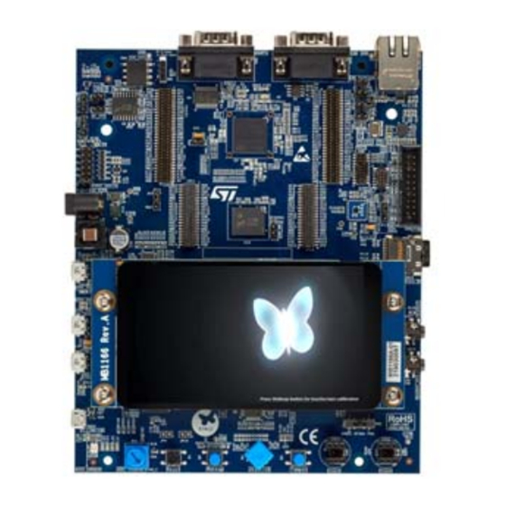
Page 56: Light Effect Module
Functional description of STM32H743I-EVAL, STM32H747I-EVAL and STM32H747I-DISCO 8.2.6 Light effect module The light effect module shows the calculation capabilities of the STM32H7 microcontroller via an advanced controlled light effect. Figure 49. TouchGFX - Light effect module 56/76 UM2222 Rev 2... -
Page 57: External Hardware Module
UM2222 Functional description of STM32H743I-EVAL, STM32H747I-EVAL and STM32H747I-DIS- 8.2.7 External hardware module The external hardware module shows how TouchGFX can communicate with other parts of the H7. In the module are the user able to view the MCU Junction temperature and adjust the screen brightness. -
Page 58: Knight Hit Zombie Game
To see the performance enhancement that the Chrom-ART Accelerator delivers, Chrom-ART can be enabled or disabled by pressing the right button, with the ST logo, in the bottom. 8.2.9... -
Page 59: Figure 53. 2048 Puzzle Game Module
UM2222 Functional description of STM32H743I-EVAL, STM32H747I-EVAL and STM32H747I-DIS- When the 2048 module is entered, the game is started and the user can interact with the game board. Figure 53. 2048 Puzzle game module To restart the game the user can select the button New Game. Simulating a game is done by pressing the Auto Play button and the tiles I being moved by the H7. -
Page 60: Embedded Wizard Demonstration
Functional description of STM32H743I-EVAL, STM32H747I-EVAL and STM32H747I-DISCO Embedded wizard demonstration 8.3.1 Overview The embedded wizard demonstration is available in binary format. To show the embedded wizard demonstration, the user needs to load the full binary file available under Demonstration/binaries - STM32CubeDemo_STM32H743-Eval_VX.Y.Z_FULL.hex Figure 55. -
Page 61: Graphic Effect Module (Only H743I-Eval)
UM2222 Functional description of STM32H743I-EVAL, STM32H747I-EVAL and STM32H747I-DIS- 8.3.3 Graphic effect module (only H743I-EVAL) The graphic effect module demonstrates the computing capabilities of the platform to render a real-time effect at full screen resolution. The implemented filters are the following: •... -
Page 62: Graphics Accelerator Module
Functional description of STM32H743I-EVAL, STM32H747I-EVAL and STM32H747I-DISCO 8.3.5 Graphics accelerator module The graphic accelerator module is used to display the Chrom-ART accelerator capabilities and how it offloads the CPU. The five operations listed below are used: • Alpha8 blend • Rectangle copy •... -
Page 63: Screen Saver Module (Only H743I-Eval)
UM2222 Functional description of STM32H743I-EVAL, STM32H747I-EVAL and STM32H747I-DIS- 8.3.7 Screen saver module (only H743I-EVAL) The screen saver module is used to display a rotating clock that provides the current time while it is spinning around the three axis (x, y and z). The spinning operation uses intensive CPU calculation to highlight the CPU capabilities. -
Page 64: Climate Cabinet
Functional description of STM32H743I-EVAL, STM32H747I-EVAL and STM32H747I-DISCO 8.3.9 Climate cabinet Overview Graphic module showing a climate cabinet application. Figure 63. Climate cabinet 8.3.10 Brick game Overview Control the paddle by touching and moving it right and left to bounce the ball and destroy all bricks. -
Page 65: Fitness Tracker
UM2222 Functional description of STM32H743I-EVAL, STM32H747I-EVAL and STM32H747I-DIS- 8.3.11 Fitness tracker Overview Graphic module showing a fitness tracker application. Figure 65. Fitness tracker 8.3.12 Paper cutter Overview Graphic module showing a paper cutter application. Figure 66. Paper cutter UM2222 Rev 2 65/76... -
Page 66: Washing Machine
Functional description of STM32H743I-EVAL, STM32H747I-EVAL and STM32H747I-DISCO 8.3.13 Washing machine Overview Graphic module showing Washing machine application. Figure 67. Washing machine 66/76 UM2222 Rev 2... -
Page 67: Functional Description Of The Stm32H745I-Disco Demonstration Modules
UM2222 Functional description of the STM32H745I-DISCO demonstration modules Functional description of the STM32H745I-DISCO demonstration modules The STM32H745I dual core Discovery board demonstration aims to highlight the dual core aspects and the analog features of the STM32H745I dual core device. The Demonstration is based on a main menu that is usable to switch between: •... -
Page 68: Eembc ® Coremark
Functional description of the STM32H745I-DISCO demonstration modules UM2222 Figure 69. System information module ® ® EEMBC CoreMark ® ® Figure 70. EEMBC CoreMark application ® ® EEMBC CoreMark is a benchmark that measures the performance of the microcontrollers (MCUs) and central processing units (CPUs) used in embedded systems. This application shows the STM32H745 device Cortex-M7 and Cortex-M4 scores based on this benchmark. -
Page 69: Oscilloscope And Signals Generator
• ~800 CoreMarks for Cortex-M4 Hardware and software steps to switch from SMPS power configuration to LDO are detailed in the file Demonstration/STM32H745-Discovery_Demo/CM7/Inc/main_common.h within the STM32CubeH7 MCU package. Oscilloscope and signals generator Figure 71. Oscilloscope and signals generator application 9.4.1... -
Page 70: Features
This GUI is available under PC_Software within the demonstration Package, to change the oscilloscope settings, visualize the acquired signals and perform mathematical processing. Communication between the GUI and the STM32H7 is ensured by UART through ST-Link Virtual COM port. Signal generator: The signal generator is based on the STM32H745 DAC to generate different signal patterns. -
Page 71: Hardware And Software Setup
Receive and visualize samples acquired by the ADC and sent by the Cortex-M4 • The communication between the PC application and the STM32H745I-DISCO is ensured by the ST-Link USB connector used as Virtual COM port • Connect the STM32H745I-DISCO USB ST-LINK port to the PC... -
Page 72: How To Use
PC Software Side: Start the PC oscilloscope application • In the Communication Settings – Select the Serial Port corresponding to the ST-Link Virtual COM – Select the Baud Rate 115200 – Click on Connect Click on Start Scope to visualize the input signal. -
Page 73: Figure 75. Pc Oscilloscope Screen
UM2222 Functional description of the STM32H745I-DISCO demonstration modules Figure 75. PC oscilloscope screen STM32H745I-DISCO board side: The user may select the type, amplitude and frequency of the signal generator from the LCD by touching the corresponding buttons. Figure 76. STM32H745I-DISCO board screen If there is no user action on the touchscreen during 15 seconds, the signal generator goes to auto mode, randomly changing the signal type, frequency and amplitude. - Page 74 Functional description of the STM32H745I-DISCO demonstration modules UM2222 The user may switch off the Cortex-M7 (D1 domain goes to standby mode): • Press User button on the STM32H745I-DISCO board to put D1-Domain in standby mode – All the STM32H745 D1 power domain goes to standby (including the Cortex-M7 and the internal FLASH and the LCD controller).
-
Page 75: Revision History
UM2222 Revision history Revision history Table 12. Document revision history Date Revision Changes 8-Dec-2017 Initial version Updated Introduction, Section 8 to add new supported boards and applications 12-Jun-2019 Added Section 9 specific to STM32H745I-DISCO UM2222 Rev 2 75/76... - Page 76 ST products and/or to this document at any time without notice. Purchasers should obtain the latest relevant information on ST products before placing orders. ST products are sold pursuant to ST’s terms and conditions of sale in place at the time of order acknowledgement.
Need help?
Do you have a question about the STM32CubeH7 and is the answer not in the manual?
Questions and answers