
Related Manuals for Rigol DS1102/4B


Summary of Contents for Rigol DS1102/4B
- Page 1 RIGOL User’s Guide Publication number UGA04107-1210 July 2008 DS1000B Series Digital Oscilloscopes DS1062/4B DS1102/4B DS1202/4B © 2008 RIGOL Technologies, Inc. All Rights Reserved...
- Page 3 RIGOL products are protected by patent law in and outside of P.R. China. Information in this publication replaces all previously corresponding material. RIGOL Technologies, Inc. reserves the right to modify or change part of or all the specifications and pricing policies at company’s sole decision.
-
Page 4: Safety Notices
Provide Proper Ventilation. Refer to the installation instructions for proper ventilation of the instrument. Do not Operate in Wet/Damp Conditions. © 2008 RIGOL Technologies, Inc. User’s Guide for DS1000B Series... - Page 5 DS1000B series Digital Oscilloscopes is designed to safely withstand occasional transient overvoltage up to 1000 Vpk. Do not use this equipment to measure circuits where transient overvoltage could exceed this level. © 2008 RIGOL Technologies, Inc. User’s Guide for DS1000B Series...
-
Page 6: Safety Terms And Symbols
CAUTION indicates that a potential damage to the instrument or other property might occur. Symbols on the Product: These symbols may appear on the Instrument: Hazardous Refer to Protective Chassis Earth Voltage Instructions Earth Terminal Ground Ground © 2008 RIGOL Technologies, Inc. User’s Guide for DS1000B Series... - Page 7 RIGOL General-Purpose Oscilloscopes RIGOL DS1000B series digital oscilloscopes offer exceptional waveform viewing and measurements in a compact, lightweight package. The DS1000B series is ideal for production test, field service, research, design, education and training involving applications of analog circuit tests and troubleshooting.
-
Page 8: Table Of Contents
To Set up the Display System ..............2-56 To Store and Recall ................2-59 To Set up the Utility ................2-69 The I/O Setup ................2-71 Preference ..................2-74 Self-Calibration ................2-75 © 2008 RIGOL Technologies, Inc. User’s Guide for DS1000B Series... - Page 9 Chapter 6 : Appendixes ............... 6-1 Appendix A: Accessories ................6-1 Appendix B: Warranty ................6-2 Appendix C: Maintenance ................ 6-3 Appendix D: Contact RIGOL ..............6-4 Index ......................i © 2008 RIGOL Technologies, Inc. User’s Guide for DS1000B Series...
-
Page 11: Chapter 1 : Getting Started
To compensate the probes „ To display a signal automatically „ To understand the vertical system „ To understand the horizontal system „ To trigger the oscilloscope „ To understand the quick function © 2008 RIGOL Technologies, Inc. User’s Guide for DS1000B Series... -
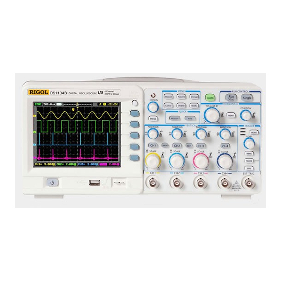
Page 12: The Front Panel And User Interface
Figure 1-1 DS1000B Series Oscilloscope’s Front Panel © 2008 RIGOL Technologies, Inc. User’s Guide for DS1000B series... - Page 13 LEVEL knob. The name with a drop shadow denotes the menu operating key, such as Waveform soft key in Storage menu. © 2008 RIGOL Technologies, Inc. User’s Guide for DS1000B Series...
- Page 14 Running status windows Trigger symbol Mark of channel1 Menu Mark of channel2 Mark of channel3 Mark of channel4 Waveform display windows Figure 1-3 Display screen © 2008 RIGOL Technologies, Inc. User’s Guide for DS1000B series...
-
Page 15: To Inspect The Instrument
Representative. If the shipping container is damaged, or the cushioning materials show signs of stress, notify the carrier as well as the RIGOL sales office. Keep the shipping materials for the carrier’s inspection. RIGOL offices will arrange for repair or replacement at RIGOL’s option without waiting for claim settlement. -
Page 16: To Perform A Functional Check
Connector (BNC) connector of CH1 or CH2. ¾ Push to connect, and twist to the right to lock the probe in place. ¾ Attach the probe tip and ground lead to the PROBE COMP connector. © 2008 RIGOL Technologies, Inc. User’s Guide for DS1000B series... - Page 17 Push the CH2, CH3, CH4 buttons to turn on channel 2, channel3, channel4, repeat steps 2 and 3. NOTE: The signal output from Probe compensator should only be used for probe compensation, not for calibration. © 2008 RIGOL Technologies, Inc. User’s Guide for DS1000B Series...
-
Page 18: To Compensate The Probes
WARNNING: To avoid electric shock while using the probe, be sure the perfection of the insulated cable, and do not touch the metallic portions of the probe head while it is connected with a voltage source. © 2008 RIGOL Technologies, Inc. User’s Guide for DS1000B series... -
Page 19: To Display A Signal Automatically
1. Connect a signal to the oscilloscope (such as channel 1) as described above. Press AUTO. The oscilloscope may change the current settings to display the signal; adjusts the vertical and horizontal scaling, the trigger coupling, type, position, level, and mode. © 2008 RIGOL Technologies, Inc. User’s Guide for DS1000B Series... -
Page 20: To Understand The Vertical System
If the channel is AC coupled, the DC component of the signal is blocked, allow you to use greater sensitivity to display the AC component of the signal. 1-10 © 2008 RIGOL Technologies, Inc. User’s Guide for DS1000B series... - Page 21 Coarse/Fine Shortcut key The Coarse/Fine vertical control can be set by simply pressing the vertical knob. © 2008 RIGOL Technologies, Inc. 1-11 User’s Guide for DS1000B Series...
-
Page 22: To Understand The Horizontal System
Delayed Scan mode and it is equal to the menu operations, MENU Delayed ON. 1-12 © 2008 RIGOL Technologies, Inc. User’s Guide for DS1000B series... - Page 23 Trig-Offset: Denotes the real position of the trigger point relative to the midpoint of the memory. In this setting, the trigger position will be changed horizontally when you turning the knob. © 2008 RIGOL Technologies, Inc. 1-13 User’s Guide for DS1000B Series...
-
Page 24: To Trigger The Oscilloscope
Trigger Level back to 0 Shortcut key Turn the knob to change the trigger level value and press the knob to set trigger level back to 0 as a shortcut key. 1-14 © 2008 RIGOL Technologies, Inc. User’s Guide for DS1000B series... - Page 25 Start an acquisition even if no valid trigger signal has been found, usually used in “Normal” or “Single” trigger mode. This button has no effect if the acquisition is already stopped. © 2008 RIGOL Technologies, Inc. 1-15 User’s Guide for DS1000B Series...
- Page 26 This function helps to view complex signals such as an AM waveform. Press Holdoff button to activate ( ) knob, then turn it to adjust Holdoff time. 1-16 © 2008 RIGOL Technologies, Inc. User’s Guide for DS1000B series...
-
Page 27: To Understand The Quick Function
2. Use Print button to perform a quick print, you can set screen quantities need to be printed or store datum to the USB disk. © 2008 RIGOL Technologies, Inc. 1-17 User’s Guide for DS1000B Series... -
Page 29: Chapter 2 : Operating Your Oscilloscope
To save and recall waveforms or setups (Storage) „ To set up utility (Utility) „ To measure automatically (Measure) „ To measure with cursors (Cursor) „ To use run control buttons (Auto, Run/Stop, Single) © 2008 RIGOL Technologies, Inc. User’s Guide for DS1000B Series... -
Page 30: To Set Up The Vertical System
Probe vertical scale readout correct. 1000X Digital filter Set up digital filter (See table 2-4). Go to the next menu page (The followings are the same, no more explanation). © 2008 RIGOL Technologies, Inc. User’s Guide for DS1000B series... - Page 31 Turn on the invert function. Invert Restore to original display of the waveform. Set “V”, “A”, “W” or “U” as the unit of Unit V/ A/ W/ U vertical channel. © 2008 RIGOL Technologies, Inc. User’s Guide for DS1000B Series...
- Page 32 Coupling AC, to set “AC” coupling. It will pass AC component of the input signal with frequency higher than 5 Hz and restraint DC component of the input signal. The waveform is displayed as Figure 2-4: © 2008 RIGOL Technologies, Inc. User’s Guide for DS1000B series...
- Page 33 Press CH1 Coupling GND, to set “GND” coupling, it disconnects the input signal. The screen displays as Figure 2-5: GND coupling Setup GND coupling Status symbol Figure 2-5 Screen display © 2008 RIGOL Technologies, Inc. User’s Guide for DS1000B Series...
- Page 34 Turn off the BW limit Press CH1 BW Limit ON, to set up bandwidth limit to “ON” status. It will restraint the frequency component higher than 20MHz. The waveform is displayed as Figure 2-7: © 2008 RIGOL Technologies, Inc. User’s Guide for DS1000B series...
- Page 35 RIGOL 20MHz BW limit Mark of BW limit Figure 2-7 Turn on the BW limit © 2008 RIGOL Technologies, Inc. User’s Guide for DS1000B Series...
- Page 36 Probe attenuation factors Corresponding settings 1:1000 1:100 1:10 0.001X 0.01X 0.1X 1:1 2:1 5:1 1X 2X 5X 10:1 20:1 50:1 10X 20X 50X 100:1 200:1 500:1 100X 200X 500X 1000:1 1000X © 2008 RIGOL Technologies, Inc. User’s Guide for DS1000B series...
- Page 37 It will be helpful to adjust the waveform in smooth steps. Fine adjustment Figure 2-9 Fine adjustment data Fine configurations Coarse/Fine Shortcut key: To change Coarse/Fine setting, not only by menu operation but also by pressing vertical knob. © 2008 RIGOL Technologies, Inc. User’s Guide for DS1000B Series...
- Page 38 Figure 2-10 and Figure 2-11 show the changes before and after the inversion respectively. Invert off Figure 2-10 The waveform before inversion Invert on Figure 2-11 The waveform after inversion 2-10 © 2008 RIGOL Technologies, Inc. User’s Guide for DS1000B series...
- Page 39 Turn off digital filter Figure 2-12 Turn off digital filter Turn on digital filter Figure 2-13 Turn on digital filter © 2008 RIGOL Technologies, Inc. 2-11 User’s Guide for DS1000B Series...
- Page 40 Upper limit <frequency> high limit. Lower limit Turn ( ) knob to set lower limit. <frequency> Back to higher level menu (The followings are the same, no more explanation). 2-12 © 2008 RIGOL Technologies, Inc. User’s Guide for DS1000B series...
-
Page 41: To Use Math Functions
CH3, CH4 source A. CH1, CH2, Define CH1, CH2, CH3 or CH4 as Source B CH3, CH4 source B. Invert the MATH waveform. Invert Restore to original waveform display. © 2008 RIGOL Technologies, Inc. 2-13 User’s Guide for DS1000B Series... - Page 42 Table 2-6 The Math menu (Page 2/2) Menu Settings Comments The multifunctional knob adjusts the vertical position of the Math waveform. The multifunctional knob adjusts the vertical amplitude of the Math waveform. 2-14 © 2008 RIGOL Technologies, Inc. User’s Guide for DS1000B series...
- Page 43 CH3, CH4 FFT source. Rectangle Hanning Select window for FFT. Window Hamming Blackman Split Display FFT waveform on half screen. Display Full screen Display FFT waveform on full screen. © 2008 RIGOL Technologies, Inc. 2-15 User’s Guide for DS1000B Series...
- Page 44 Average. To display FFT waveforms with a large dynamic range, use the dBVrms scale. The dBVrms scale displays component magnitudes using a log scale. 2-16 © 2008 RIGOL Technologies, Inc. User’s Guide for DS1000B series...
- Page 45 It’s normally half of the sample rate. This frequency is called the Nyquist frequency. Frequency above the Nyquist frequency will be under sampled, causing a situation known as aliasing. © 2008 RIGOL Technologies, Inc. 2-17 User’s Guide for DS1000B Series...
-
Page 46: To Use Ref Function
Source CH3, CH4, waveforms will be compared with MATH the reference waveforms. Internal Select memory location in scope. location external Select memory location out scope. 2-18 © 2008 RIGOL Technologies, Inc. User’s Guide for DS1000B series... - Page 47 Go to import menu (see table 2-14). Figure 2-23 Table 2-13 REF menu when using external memory (Page 3/3) Menu settings comments Reset Reset REF waveform. Import Go to import menu (see table 2-18). © 2008 RIGOL Technologies, Inc. 2-19 User’s Guide for DS1000B Series...
- Page 48 (see table 2-15). Import Import the REF file to internal memory. Delete Delete file. File The screen of Import and Export as follows Figure 2-25 Import of export the figure 2-20 © 2008 RIGOL Technologies, Inc. User’s Guide for DS1000B series...
- Page 49 Move the focus point to next location. To delete chosen letter. Save Execute the operation. The screen of Export is as follows. Figure 2-27 Figure export © 2008 RIGOL Technologies, Inc. 2-21 User’s Guide for DS1000B Series...
- Page 50 Set up new file in Path and File. (Folder) Set up new folder in directory. Delete File Delete chosen file (Folder). (Folder) The screen of Save is as follows: Figure 2-29 The figure of save 2-22 © 2008 RIGOL Technologies, Inc. User’s Guide for DS1000B series...
- Page 51 Execute the saving operation. The screen of File Name input is as follows: The File name key in pane Switch Capital on/off Switch Chinese/English Figure 2-31 File Name inputting interface © 2008 RIGOL Technologies, Inc. 2-23 User’s Guide for DS1000B Series...
- Page 52 Switch among Path, Directory and Explorer Directory File. File Import the REF file into internal Import memory. The screen of Import is as follows: Figure 2-33 The figure of import 2-24 © 2008 RIGOL Technologies, Inc. User’s Guide for DS1000B series...
- Page 53 Access page 2 of REF menu, and then press button No.2 to save the current waveform on the screen to internal or external memory as a reference waveform. NOTE: The Reference function is not available in X-Y mode. © 2008 RIGOL Technologies, Inc. 2-25 User’s Guide for DS1000B Series...
-
Page 54: Turn On Or Off Channels
No indicator black letter with navy blue background Selected CH4 navy blue letter with black background Channel4(CH4) No indicator Math (black letter) MATH Selected Math (purple letter) No indicator 2-26 © 2008 RIGOL Technologies, Inc. User’s Guide for DS1000B series... -
Page 55: To Apply The Vertical Knobs
During the vertical positioning, a position message is displayed on the left bottom of the screen, in the same color along with the corresponding channel. The unit is V (Volts). © 2008 RIGOL Technologies, Inc. 2-27 User’s Guide for DS1000B Series... -
Page 56: To Set Up The Horizontal System
Delayed Scan time base. Horizontal Menu. Press the horizontal MENU button to display the horizontal menu. The settings of this menu are listed in the following table. 2-28 © 2008 RIGOL Technologies, Inc. User’s Guide for DS1000B series... - Page 57 In Roll Mode, the waveform display updates from right to left. Adjust the trigger position to the Trig-offset Reset center of the memory. Figure 2-36 Status bar and mark for Horizontal control © 2008 RIGOL Technologies, Inc. 2-29 User’s Guide for DS1000B Series...
- Page 58 DC. Time/Div: Horizontal scale. If the waveform acquisition is stopped (using the Run/Stop button), the Time/Div control expands or compresses the waveform. 2-30 © 2008 RIGOL Technologies, Inc. User’s Guide for DS1000B series...
- Page 59 Delayed Scan. The value at top of the screen is the main time base and the value on the center bottom means the Delayed Scan time base. © 2008 RIGOL Technologies, Inc. 2-31 User’s Guide for DS1000B Series...
- Page 60 Delayed Scan Shortcut Key: Delayed Scan function can be activated not only by menu but also by pressing horizontal knob. 2-32 © 2008 RIGOL Technologies, Inc. User’s Guide for DS1000B series...
- Page 61 The following modes or functions will not work in X-Y format. Cursor Measurements excluding manual mode REF and MATH Operations Delayed Scan Mode Vector Display Mode Horizontal knob Trigger Controls(excluding MODE button) © 2008 RIGOL Technologies, Inc. 2-33 User’s Guide for DS1000B Series...
-
Page 62: To Set Up The Trigger System
Force to create a trigger signal and the function is mainly used in Normal and Single mode MENU: The button that activates the trigger controls menu. Figure 2-39 Trigger controls 2-34 © 2008 RIGOL Technologies, Inc. User’s Guide for DS1000B series... -
Page 63: Trigger Modes
Pulse: Use this trigger mode to catch pulses with certain pulse width. Video: Use video trigger mode on fields or lines for standard video signals. Pattern: Recognising trigger by searching specified code. Alternative: Trigger on non-synchronized signals. © 2008 RIGOL Technologies, Inc. 2-35 User’s Guide for DS1000B Series... -
Page 64: Edge Trigger
Acquire waveform even no trigger occurred. Normal Acquire waveform when trigger occurred. Single When trigger occurs, acquire one waveform then stop. Set up To go to Set Up menu, see table 2-36 2-36 © 2008 RIGOL Technologies, Inc. User’s Guide for DS1000B series... -
Page 65: Pulse Width Trigger
To go to Set Up menu, see table 2-36. Note: The Pulse width adjust range is 20ns ~ 10s. When the condition is met, it will trigger and acquire the waveform. © 2008 RIGOL Technologies, Inc. 2-37 User’s Guide for DS1000B Series... -
Page 66: Video Trigger
All Lines Trigger on all lines. Line Num Trigger on a specified line. Sync Odd field Select to trigger on odd field. Even field Select to trigger on even field. 2-38 © 2008 RIGOL Technologies, Inc. User’s Guide for DS1000B series... - Page 67 Lets oscilloscope to trigger one time in Single the suitable trigger condition, and then stop. Set Up To go to set up menu, see Table 2-36. © 2008 RIGOL Technologies, Inc. 2-39 User’s Guide for DS1000B Series...
- Page 68 Sync Pulses: When Normal Polarity is selected, the trigger always occurs on negative-going sync pulses. If the video signal has positive-going sync pulses, use the inverted Polarity. Figure 2-46 Video Trigger: Line Synchronization Figure 2-47 Video Trigger: Field Synchronization 2-40 © 2008 RIGOL Technologies, Inc. User’s Guide for DS1000B series...
-
Page 69: Pattern Trigger
Sweep Normal Acquire waveform when trigger occurred. Single When trigger occurs, acquire waveform then stop. Set up To go to set up menu, see Table 2-36. © 2008 RIGOL Technologies, Inc. 2-41 User’s Guide for DS1000B Series... - Page 70 RIGOL Figure 2-49 Pattern trigger: set code as falling edge 2-42 © 2008 RIGOL Technologies, Inc. User’s Guide for DS1000B series...
-
Page 71: Alternative Trigger
Trigger on falling edge. edge Edge type both rising edge Trigger on both ring & falling edge. falling edge Set up To go to set up menu. See Table 2-36 © 2008 RIGOL Technologies, Inc. 2-43 User’s Guide for DS1000B Series... - Page 72 (-Pulse width equal to) To set up width value of Settings the pulse. <Pulse width > To go to set up menu. See Set Up Table 2-36. 2-44 © 2008 RIGOL Technologies, Inc. User’s Guide for DS1000B series...
- Page 73 Odd field Select to trigger on odd field Even field or even field. PAL/SECM Standard Select Video standard. NTSC To go to set up menu, see Set Up Table 2-36. © 2008 RIGOL Technologies, Inc. 2-45 User’s Guide for DS1000B Series...
-
Page 74: Trigger Settings
Passes high frequency component. HF reject Blocks high frequency component, passes low frequency component. Sensitivity Set trigger sensitivity. <Sensitivity Setting> Set time slot before another Holdoff trigger event. <Holdoff Setting> 2-46 © 2008 RIGOL Technologies, Inc. User’s Guide for DS1000B series... - Page 75 Table 2-36 The Trigger Set Up menu Menu Settings Comments Sensitivity Set trigger sensitivity. <Sensitivity Setting> Set time slot before another Holdoff trigger event. <Holdoff Setting> Holdoff Reset Holdoff time to 100ns. Reset © 2008 RIGOL Technologies, Inc. 2-47 User’s Guide for DS1000B Series...
-
Page 76: Trigger Holdoff
3. Turn the multi function knob ( ) to change Holdoff time until waveform is stable. 4. Press Trigger Hold off reset to reset the Holdoff time to its default value. 2-48 © 2008 RIGOL Technologies, Inc. User’s Guide for DS1000B series... - Page 77 This sweep mode allows the oscilloscope to acquire waveforms even when it does not detect a trigger condition. If no trigger condition occurs while the oscilloscope is waiting for a specific period (as determined by the time-base © 2008 RIGOL Technologies, Inc. 2-49 User’s Guide for DS1000B Series...
- Page 78 The data is collected before and after trigger. The trigger position is typically set at the horizontal center of the screen. In the full-screen display the 6div data of pre-trigger and delayed trigger can be 2-50 © 2008 RIGOL Technologies, Inc. User’s Guide for DS1000B series...
- Page 79 0.1div-1.0div, which means when it sets to 1.0div; the trigger circuit will not affect any signal with peak-peak amplitude less than 1.0div, so as to avoid the influence of the noise. © 2008 RIGOL Technologies, Inc. 2-51 User’s Guide for DS1000B Series...
-
Page 80: To Set Up The Sampling System
Peak Detect Acquisition mode. Real-Time Real-time sampling mode. Sampling Equ-Time Equivalent sampling mode. Set the interpolation as Sinx/x. Sinx/x Set the interpolation as linearity. Sa Rate Display sampling rate. 2-52 © 2008 RIGOL Technologies, Inc. User’s Guide for DS1000B series... - Page 81 Signal that contains noise, and without average sampling Figure 2-63 Display signal after average 256 times sampling Note: Select Real-time acquisition to observe the single-shot or pulse signals. Select Equ-Time to observe high frequency repetitive signals. © 2008 RIGOL Technologies, Inc. 2-53 User’s Guide for DS1000B Series...
- Page 82 Stop Acquisition: When the scope is acquiring waveforms, the waveforms is in a live status; when acquisition is stopped, frozen waveform will be displayed, the position and scale can still be adjusted by vertical control and horizontal control. 2-54 © 2008 RIGOL Technologies, Inc. User’s Guide for DS1000B series...
- Page 83 2 to 256. Peak Detect: Peak Detect mode captures the maximum and minimum values of a signal, and finds highest and lowest record points over many acquisitions. © 2008 RIGOL Technologies, Inc. 2-55 User’s Guide for DS1000B Series...
-
Page 84: To Set Up The Display System
Clear all existing waveforms from Clear screen. Infinite The sample points remain displayed Persist until turn the persistence “OFF”. Turn off the persistence function. Intensity Set up waveform intensity. < > percentage 2-56 © 2008 RIGOL Technologies, Inc. User’s Guide for DS1000B series... - Page 85 To show the accumulated acquired waveforms when the acquisition is stopped. Classical Modern To set the display screen of the Skin Tradition oscilloscope Succinct © 2008 RIGOL Technologies, Inc. 2-57 User’s Guide for DS1000B Series...
- Page 86 Refresh rate: It is an important performance of digital oscilloscopes. It means the number of display refreshing per second and it will affect the ability to observe signal. Adjusting waveform intensity Turn the multifunctional knob ( ) to adjust waveform intensity. 2-58 © 2008 RIGOL Technologies, Inc. User’s Guide for DS1000B series...
-
Page 87: To Store And Recall
The waveform files, setup files, 8 or 24 bits format bitmap files, CSV format files and PNG (Portable Network Graphics format) files in external memory can be created and deleted. System supports English/Chinese file name input. © 2008 RIGOL Technologies, Inc. 2-59 User’s Guide for DS1000B Series... - Page 88 Create or delete PNG format files. Create or delete CSV files. Factory Recall factory setups. Load Recall factory setups or files. Go to disk manage menu (see Table Disk Mana. 2-48). 2-60 © 2008 RIGOL Technologies, Inc. User’s Guide for DS1000B series...
- Page 89 Go to menu for external memory External operation (see Table 2-47). Go to disk manage menu (see Table Disk Mana. 2-48). © 2008 RIGOL Technologies, Inc. 2-61 User’s Guide for DS1000B Series...
- Page 90 Go to menu for external memory External operation (see Table 2-47). Go to disk manage menu (see Table Disk Mana. 2-48). 2-62 © 2008 RIGOL Technologies, Inc. User’s Guide for DS1000B series...
- Page 91 Recall waveform files and setup files Load from the internal memory location. Save waveform files and setup files to Save the internal memory location. Delete Delete selected files. Files © 2008 RIGOL Technologies, Inc. 2-63 User’s Guide for DS1000B Series...
- Page 92 Recall waveform and setup from Load USB storage device. File system is as follows: Path Back to previous Files folder Current directory File info. Figure 2-77 File system display screen 2-64 © 2008 RIGOL Technologies, Inc. User’s Guide for DS1000B series...
- Page 93 USB flash drive, the screen will appear a U-disk selection interface as Figure 2-78. Turn the multifunction knob to choose the driver. The front one marked “F:”, the rear one “G:”. © 2008 RIGOL Technologies, Inc. 2-65 User’s Guide for DS1000B Series...
-
Page 94: Disk Management
Pass/Fail file. Figure 2-80 Table 2-49 The Disk Management menu (Page 2/2) Menu Settings Comments Rename To rename a file (see Table 2-50). Disk info Display disk information. 2-66 © 2008 RIGOL Technologies, Inc. User’s Guide for DS1000B series... - Page 95 To move the focus point to the next location. To delete chosen letter. Rename the file. The Rename system screen is as follows: Figure 2-82 Rename the file © 2008 RIGOL Technologies, Inc. 2-67 User’s Guide for DS1000B Series...
- Page 96 To ensure the setups being saved properly, only after the settings are changed for more than 5 seconds, user could turn off the instrument. The oscilloscope can store 10 settings permanently and can restore at anytime. 2-68 © 2008 RIGOL Technologies, Inc. User’s Guide for DS1000B series...
-
Page 97: To Set Up The Utility
Turn beeper sound on/off. (OFF) Turn off Frequency Counter. Counter Turn on Frequency Counter. Select languages. Language English (More languages may be added Japanese in later firmware versions.) Français © 2008 RIGOL Technologies, Inc. 2-69 User’s Guide for DS1000B Series... - Page 98 Note: Self-Cal: Oscilloscope will calibrate parameter of vertical system (CH1, CH2, CH3, CH4 and Ext); horizontal system and trigger system .The oscilloscope can normally work under different environments. 2-70 © 2008 RIGOL Technologies, Inc. User’s Guide for DS1000B series...
-
Page 99: The I/O Setup
Auto Detect Set USB device function, connect USB Computer Device interface to the needed device. PictBridge Set the GPIB address, the address range GPIB# <Address> is from 0 to 30. © 2008 RIGOL Technologies, Inc. 2-71 User’s Guide for DS1000B Series... - Page 100 Figure 2-89 Table 2-55 LAN Setting menus Menu Display Comments LAN Init Load Load the LAN initial data Move up/down the setting focus Move left/right the setting focus 2-72 © 2008 RIGOL Technologies, Inc. User’s Guide for DS1000B series...
- Page 101 DHCP: Dynamic Host Configuration Protocol Auto IP: Auto IP Manual: Manual IP MAC: Medium Access Control Layer protocol VISA: Virtual Instrument System Architecture IP Configure Mode IP Address Subnet Mask Gateway DNS Server © 2008 RIGOL Technologies, Inc. 2-73 User’s Guide for DS1000B Series...
-
Page 102: Preference
Sticky key: If sticky feature is turned ON, when adjusting positions (CH1, CH2 CH3 CH4, Math, Ref, Trigger level and Trigger offset), the waveform will stop at zero position until next adjustment, for the ease of getting back to initial positions. 2-74 © 2008 RIGOL Technologies, Inc. User’s Guide for DS1000B series... -
Page 103: Self-Calibration
The Self-Calibration screen is shown as in Figure 2-84. Figure 2-92 The Self-Calibration menu NOTE: The oscilloscope must have been working or warm-up at least 30-minutes before running self-calibration to get best accuracy. © 2008 RIGOL Technologies, Inc. 2-75 User’s Guide for DS1000B Series... -
Page 104: Pass/Fail
Output and beep when Pass condition Pass+ detected. Stop Stop test when output occur. on Output Continue test when output occur. Mask Setting Go to mask setting menu. *Note: The beeper should be opened. 2-76 © 2008 RIGOL Technologies, Inc. User’s Guide for DS1000B series... -
Page 105: Mask Setting
2-10 . Recall mask setting file from internal Load memory (see table 2-57). Go to import/export menu (same as Imp./Exp. REF import/export menu. see table 2-12). © 2008 RIGOL Technologies, Inc. 2-77 User’s Guide for DS1000B Series... - Page 106 Go to save menu (same as REF save Save menu, see table 2-10). Load Go to load menu (see Table 2-57). Go to import menu. (Same as REF Import import menu, see table 2-12). 2-78 © 2008 RIGOL Technologies, Inc. User’s Guide for DS1000B series...
- Page 107 Table 2-63 The Load menu Menu Settings Comments Path Switch among Path, Directory and Explorer Directory File. File Load Recall the specified file. NOTE: Pass/Fail function is unavailable in X-Y mode. © 2008 RIGOL Technologies, Inc. 2-79 User’s Guide for DS1000B Series...
-
Page 108: Print Setting
Set the print mode as normal. PrintMod PictBridge Set the print mode as PictBridge. print Execute the print operation. Abort Abort the printing. Inquire about the current status of Status the printer. 2-80 © 2008 RIGOL Technologies, Inc. User’s Guide for DS1000B series... - Page 109 Turn off then inversion of printing color Figure 2-103 Table 2-68 The print setup menu (Page 4/4) Menu Settings Comments Grayscale To set the print image as grayscale palette Color or color. © 2008 RIGOL Technologies, Inc. 2-81 User’s Guide for DS1000B Series...
-
Page 110: Waveform Recorder
Record stopped, press to Start (Run) Operate recording. (Stop) Press to stop recording. Figure 2-105 Table 2-70 The Record menu (Page 2/2) Menu Settings Comments Set time interval between Interval record frames. <1.00ms-1000s> 2-82 © 2008 RIGOL Technologies, Inc. User’s Guide for DS1000B series... - Page 111 Frame <1-1000> Current Select current frame to be Frame <1-1000> played. End Frame Set End frame. <1-1000> Note: the Run/Stop button can also replay or continue the waveform display. © 2008 RIGOL Technologies, Inc. 2-83 User’s Guide for DS1000B Series...
- Page 112 Menu Settings Comments Save recorded waveform to internal Save memory location. Recall recorded waveform from Load internal memory location. Go to import/export menu (Same as Imp./Exp. REF import/export menu). 2-84 © 2008 RIGOL Technologies, Inc. User’s Guide for DS1000B series...
- Page 113 Go to save menu (same as REF save Save menu. see table 2-10). Load Go to load menu (see Table 2-57). Go to import menu. (Same as REF Import import menu, see table 2-12). © 2008 RIGOL Technologies, Inc. 2-85 User’s Guide for DS1000B Series...
-
Page 114: System Information
The system information includes: Product Model, Serial Number, Software Version and Installed Module of the oscilloscope. Follow the prompting message “<<Press ‘RUN’ Key to Exit the Test>>" to exit the information display interface. 2-86 © 2008 RIGOL Technologies, Inc. User’s Guide for DS1000B series... -
Page 115: Language
The DS1000B series oscilloscopes have multi-language user menu, choose as your desire. Press Utility Language to select the language. Press button No.4 until the desired language appears. Figure 2-112 The language selection screen © 2008 RIGOL Technologies, Inc. 2-87 User’s Guide for DS1000B Series... -
Page 116: Date And Time
Table 2-76 Time setting menu Menu Settings Comments Close time display Display Open time display Move up/down the setting focus Move left/right the setting focus Save the current settings 2-88 © 2008 RIGOL Technologies, Inc. User’s Guide for DS1000B series... -
Page 117: To Measure Automatically
CH1, CH2, Select CH1 or CH2 as source channel Source CH3, CH4 for measurement. Voltage Select measure voltage parameter. Time Select measure time parameter. Clear Clear measurement result on screen. © 2008 RIGOL Technologies, Inc. 2-89 User’s Guide for DS1000B Series... - Page 118 To configure the delay and phase channels, in order to measure Delay/Phas delay and phase value relative to e Setup time measurement between any two vertical channels form CH1 to CH4. 2-90 © 2008 RIGOL Technologies, Inc. User’s Guide for DS1000B series...
-
Page 119: Quick Measurement Setup
Figure 2-118 Table 2-79 The quick measure menu Menu Settings Comments Item1 To specify Item1, Item2 and Item3 respectively, each item Item2 can be chosen from 22 kind’s measure items. Item3 © 2008 RIGOL Technologies, Inc. 2-91 User’s Guide for DS1000B Series... -
Page 120: Delay/Phase Setup
Press Measure Delay/Phase Setup button and go to the delay/phase setup menu. Figure 2-119 Table 2-80 The delay/phase setup menu. Menu Settings Comments DelayA Delay measurement as one of CH1,CH2,CH3,CH4 DelayB PhaseA Phase measurement as one of PhaseB CH1,CH2,CH3,CH4 2-92 © 2008 RIGOL Technologies, Inc. User’s Guide for DS1000B series... -
Page 121: Voltage Measurements
Preshoot: Defined as (Vmin-Vbase)/Vamp, useful for square and pulse waveforms. Average: The arithmetic mean over the entire waveform. Vrms: The true Root Mean Square voltage over the entire waveform. © 2008 RIGOL Technologies, Inc. 2-93 User’s Guide for DS1000B Series... - Page 122 Voltage of a waveform. Figure 2-123 Table 2-83 The Voltage Measurement menu (Page 3/3) Menu Settings Comments Measure overshoots Overshoot percentage of an edge. Measure preshoot in percentage Preshoot of an edge. 2-94 © 2008 RIGOL Technologies, Inc. User’s Guide for DS1000B series...
-
Page 123: Time Measurements
Phase A B : The phase between the channel A and channel B at the falling edge. +Duty: +Duty Cycle, defined as +Width/Period -Duty: -Duty Cycle, defined as -Width/Period. © 2008 RIGOL Technologies, Inc. 2-95 User’s Guide for DS1000B Series... - Page 124 Measure phase difference Phase A Æ B between two channels at the rising edge Measure phase difference Phase A Æ B between two channels at the falling edge 2-96 © 2008 RIGOL Technologies, Inc. User’s Guide for DS1000B series...
- Page 125 Maximum 3 results could be displayed at the same time. When there is no room, the next new measurement result will make the previous results moving left out of screen. © 2008 RIGOL Technologies, Inc. 2-97 User’s Guide for DS1000B Series...
- Page 126 Clear the measure values: press No.4 button Clear to clear away all of the auto measure values would disappear from the screen. Turn on/off the mass measurement Clear measured data from screen Figure 2-128 The explanation of the menu 2-98 © 2008 RIGOL Technologies, Inc. User’s Guide for DS1000B series...
-
Page 127: To Measure With Cursors
These cursors demonstrate the electrical meanings of these measurements. NOTE: The Auto Measure mode for Cursor measuring will take no effect without automatic measurements. © 2008 RIGOL Technologies, Inc. 2-99 User’s Guide for DS1000B Series... -
Page 128: Manual Mode
3. Select the cursors type by pressing soft button as Cursor Type X or Y. 4. Move the cursors to adjust the increment between the cursors:(Details in the following Table) 2-100 © 2008 RIGOL Technologies, Inc. User’s Guide for DS1000B series... - Page 129 Cursor X: Cursor X appears as vertical lines on the display to measure horizontal parameters. Usually it indicates the time of trigger excursion. When the source is set as FFT, X means frequency. © 2008 RIGOL Technologies, Inc. 2-101 User’s Guide for DS1000B Series...
-
Page 130: Track Mode
Table 2-90 The Cursor usage Cursor Operation Cursor A Turn the multifunctional knob ( ) to move cursor A horizontally. Cursor B Turn the multifunctional knob ( ) to move Cursor B horizontally. 2-102 © 2008 RIGOL Technologies, Inc. User’s Guide for DS1000B series... - Page 131 X): Time between cursors, units in seconds. △ X), units in Hz, kHz, MHz, GHz. △ Vertical space between cursor 1 and 2 ( Y): Voltage between cursors, units in V. © 2008 RIGOL Technologies, Inc. 2-103 User’s Guide for DS1000B Series...
-
Page 132: Auto Mode
Auto Measure Mode of Cursor Measurement There will be no cursor display if no parameters are chosen in Measure menu. The oscilloscope could move cursor automatically to measure 22 parameters in Measure menu. 2-104 © 2008 RIGOL Technologies, Inc. User’s Guide for DS1000B series... -
Page 133: To Use Run Control Buttons
Press to display falling edge of the waveform and measure its fall time Fall Edge automatically. Press to cancel all the Auto Set Undo actions, the oscilloscope will recover to its previous status. © 2008 RIGOL Technologies, Inc. 2-105 User’s Guide for DS1000B Series... - Page 134 NOTE: In STOP status, the volts/div and horizontal time base can be adjusted in a fixed limit. That is, to zoom in/out the signal in vertical and horizontal directions. 2-106 © 2008 RIGOL Technologies, Inc. User’s Guide for DS1000B series...
-
Page 135: Chapter 3 : Application & Examples
Press Time Freq to select the frequency measurements and the result will be displayed on the screen. NOTE: The frequency, period, and peak-to-peak measurements are shown on the screen and are updated periodically. © 2008 RIGOL Technologies, Inc. User’s Guide for DS1000B Series... -
Page 136: Example 2: View A Signal Delay Caused By A Circuit
Press Time to select the measurement Type. Press Delay A B to display the result on the screen. You can see the change of the waveform in the following figure: Figure 3-1 Delay of the signals © 2008 RIGOL Technologies, Inc. User’s Guide for DS1000B Series... -
Page 137: Example 3: Capture A Single-Shot Signal
It is useful to observe the waveform before the occurrence of the noise. © 2008 RIGOL Technologies, Inc. User’s Guide for DS1000B Series... -
Page 138: Example 4: To Reduce The Random Noise On A Signal
8 kHz. Use LF Reject to remove low frequency signals such as power line noise from the trigger path. 4. To reduce the noise by setting the acquisition type and adjust the waveform intensity © 2008 RIGOL Technologies, Inc. User’s Guide for DS1000B Series... - Page 139 To reduce the noise it can also be achieved by reducing the intensity of the display. NOTE: It is normal that the refresh rate will slow down when the average acquisition mode is ON. © 2008 RIGOL Technologies, Inc. User’s Guide for DS1000B Series...
-
Page 140: Example 5: Making Cursor Measurements
5. Turn ( ) knob to place cursor B on the second peak of the wave. Observe the data in time and frequency displayed on the screen. Figure 3-4 Waveform display © 2008 RIGOL Technologies, Inc. User’s Guide for DS1000B Series... - Page 141 Observe the following measurements in the cursor menu: (See Figure 3-5) The delta voltage (peak-to-peak voltage of the waveform) The voltage at Cursor 1 The voltage at Cursor 2 Figure 3-5 Waveform display © 2008 RIGOL Technologies, Inc. User’s Guide for DS1000B Series...
-
Page 142: Example 6: The Application Of The X-Y Operation
8. Adjust the vertical knobs to a desirable waveform display. 9. Apply the Ellipse method to observe the phase difference between the two channels. (See Figure 3-6) © 2008 RIGOL Technologies, Inc. User’s Guide for DS1000B Series... - Page 143 If the main axis of the ellipse is at I and III quadrant, T must be in the range of (0~π/2) or (3π/2~2π). If the main axis is at II and IV quadrant, T must be in the range of (π/2~π) or (π~3π/2). © 2008 RIGOL Technologies, Inc. User’s Guide for DS1000B Series...
-
Page 144: Example 7: Triggering On A Video Signal
DS1000B series triggers on the Odd field or Even field. To avoid confusion when Odd field and Even field trigger simultaneously, choose Odd field or Even field as step 5 above. 3-10 © 2008 RIGOL Technologies, Inc. User’s Guide for DS1000B Series... - Page 145 8. Turn the horizontal knob to observe a complete waveform on the screen. Figure 3-8 Waveform display © 2008 RIGOL Technologies, Inc. 3-11 User’s Guide for DS1000B Series...
-
Page 146: Example 8: Fft Cursor Measurement
No.3 button to specify source as MATH. 5. Turn ( ) knob to move the cursor A and cursor B to a point of interest. Figure 3-9 Cursor Measurement (Type Y) 3-12 © 2008 RIGOL Technologies, Inc. User’s Guide for DS1000B Series... - Page 147 RIGOL Figure 3-10 Cursor Measurement (Type X) © 2008 RIGOL Technologies, Inc. 3-13 User’s Guide for DS1000B Series...
-
Page 148: Example 9: Pass/Fail Test
Create Mask to create a new mask. Press Output to select the expected outputting waveforms. Press Operate to start the test. Figure 3-11 Waveform display 3-14 © 2008 RIGOL Technologies, Inc. User’s Guide for DS1000B Series... -
Page 149: Chapter 4 : Troubleshooting
(2) Ensure the power switch is turned on. (3) After the above inspection, restart the oscilloscope. (4) If the problem still remains, please contact RIGOL for help. After the signal acquisition the waveform does not appear: (1) Check the probes connected with the signals. - Page 150 (2) If connecting to a PictBridge printer or the printing is unsuccessful, maybe the USB Device menu has been set to “Computer”. You should switch it to be “Auto Detect” or “PictBridge”. If necessary, restart the oscilloscope. © 2008 RIGOL Technologies, Inc. User’s Guide for DS1000B Series...
-
Page 151: Chapter 5 : Specifications
Must perform the Self Calibration operation, accessible through the Utility menu, if the operating temperature changes by more than 5 . All specifications are guaranteed unless noted “typical”. © 2008 RIGOL Technologies, Inc. User’s Guide for DS1000B Series... -
Page 152: Specifications
16k samples for half channel 8k samples for each channel Scan speed Range 1ns/div~50s/div, DS1202/4B (Sec/div) 2ns/div~50s/div, DS1102/4B 5ns/div~50s/div, DS1062/4B 1-2-5 Sequence Sample Rate and ±50ppm (over any≥1ms time interval) Delay Time Accuracy © 2008 RIGOL Technologies, Inc. User’s Guide for DS1000B Series... - Page 153 Add 50mV for settings from >200mV/div to 10V/div Delta Volts Delta Volts between any two averages of 16 waveforms Measurement acquired under same setup and ambient Accuracy (Average conditions: ±(DC Gain Accuracy×reading + 0.05 div) Acquisition Mode) © 2008 RIGOL Technologies, Inc. User’s Guide for DS1000B Series...
- Page 154 Pattern Trigger Pattern setup H, L, X, Alternate Trigger Trigger CH1, Edge, Pulse, Video CH2, CH3, CH4 Measurements Manual Voltage difference between cursors (∆V) Cursor Time difference between cursors (∆T) © 2008 RIGOL Technologies, Inc. User’s Guide for DS1000B Series...
- Page 155 [1] Half channel indicates selecting one of the channels in CH1 and CH2, or in CH3 and CH4. [2] This is the highest specification, the specific specifications are as follows: DS1202/4B: 50GSa/s DS1102/4B: 25GSa/s DS1062/4B: 10GSa/s © 2008 RIGOL Technologies, Inc. User’s Guide for DS1000B Series...
-
Page 156: General Specifications
+35 ~ +40 : ≤60% relative humidity Altitude Operating 3,000 m or below Non-operating 15,000 m or below Mechanical Size Width 325mm Height 159mm Depth 133 mm Heavy Without package Packaged 4.3 kg © 2008 RIGOL Technologies, Inc. User’s Guide for DS1000B Series... - Page 157 RIGOL IP Degree IP2X Calibration Interval The recommended calibration interval is one year © 2008 RIGOL Technologies, Inc. User’s Guide for DS1000B Series...
-
Page 159: Chapter 6 : Appendixes
A CD-ROM (including User’s Guide an application software) A Warranty Card Optional accessories: BNC Cable RS232 Cable DS1000B special convenient soft bag All accessories (standard and optional) are available by contacting your local RIGOL office. © 2008 RIGOL Technologies, Inc. User’s Guide for DS1000B Series... -
Page 160: Appendix B: Warranty
To get repair service or obtain a copy of the whole warranty statement, please contact with your nearest RIGOL sales and service office. RIGOL does not provide any other warranty items except the one being provided by this summary and the warranty statement. The warranty items include but not being subjected to the hinted guarantee items related to tradable characteristic and any particular purpose. -
Page 161: Appendix C: Maintenance
Use a soft cloth dampened with water to clean the instrument. NOTE: To avoid damage to the surface of the instrument or probes, do not use any abrasive or chemical cleaning agents. © 2008 RIGOL Technologies, Inc. User’s Guide for DS1000B Series... -
Page 162: Appendix D: Contact Rigol
RIGOL Technologies, Inc. 156# CaiHe Village, ShaHe Town, ChangPing District, Beijing, China Post Code: 102206 Overseas: Contact the local RIGOL distributors or sales office. For the latest product information and service, visit our website: www.rigolna.com © 2008 RIGOL Technologies, Inc. -
Page 163: Index
Single Trigger ......2-50 Functional check ......1-6 Slope Trigger ......2-41 GND Coupling ......2-5 STORAGE ......... 2-59 Hamming Window ....2-17 Sync Pulses....... 2-40 Hanning Window ...... 2-17 Trigger ........5-4 © 2008 RIGOL Technologies, Inc. User’s Guide for DS1000B Series... - Page 164 Trigger System ......2-34 Video Signal ......3-10 Troubleshooting ......4-5 Video Trigger ......2-38 UTILITY ........2-69 X-Y .......... 2-30 Vertical ........5-3 Y-T .......... 2-30 Vertical System ......2-2 © 2008 RIGOL Technologies, Inc. User’s Guide for DS1000B Series...
Need help?
Do you have a question about the DS1102/4B and is the answer not in the manual?
Questions and answers