
Subscribe to Our Youtube Channel
Summary of Contents for Optelecom-nkf Siqura C-54 E-MC
- Page 1 User Manual Siqura C-54 E-MC Firmware Version 2.0 4-channel digital MPEG-2/4 & MJPEG video server with VMD and data...
-
Page 3: Table Of Contents
Contents Contents INTRODUCTION....................1 SAFETY INFORMATION ................... 3 2.1...................3 RAINED ERSONNEL 2.2..................3 AFETY EQUIREMENTS 2.3. (C-54 E-MC /SFP)...............3 PTICAL AFETY 2.4. EMC ......................4 2.5. ESD......................4 2.6..................4 ARE AND AINTENANCE 2.7....................5 RODUCT ISPOSAL PRODUCT DESCRIPTION................. 7 3.1....................7 RODUCT VERVIEW... - Page 4 Contents 7.7.1. General....................36 7.7.2. Encoder 1/2..................38 7.7.3. Live View Encoder ................. 50 7.7.4. OSD (On Screen Display)................ 52 7.7.5. VMD (Video Motion Detection) ..............57 7.8. RS-422/485..................63 7.9. PTZ ......................68 7.10. D ..................71 EVICE ANAGEMENT 7.10.1.
-
Page 5: Introduction
Introduction INTRODUCTION Document scope This manual applies to Optelecom-NKF’s digital video server, C-54 E-MC, version 2.0. It offers detailed information on: >> Product features >> How to install the module >> How to make connections >> How to configure the module’s settings... -
Page 7: Safety Information
Failure to comply with any precaution, warning, or instruction noted in the manual is in violation of the standards of design, manufacture, and intended use of the module. Optelecom-NKF assumes no liability for the customer’s failure to comply with any of these safety requirements. -
Page 8: Emc
Safety Information Use of controls or adjustments or procedures other than those specified herein may result in hazardous radiation exposure. The installer is responsible for ensuring that the label depicted below (background: yellow; border and text: black) is present in the restricted locations where this equipment is installed. -
Page 9: Product Disposal
Safety Information 2.7. Product Disposal Recycling The unit contains valuable materials which qualify for recycling. In the interest of protecting the natural environment, properly recycling the unit at the end of its service life is imperative. Battery When processing the printed circuit board, dismantling the lithium battery calls for special attention. -
Page 11: Product Description
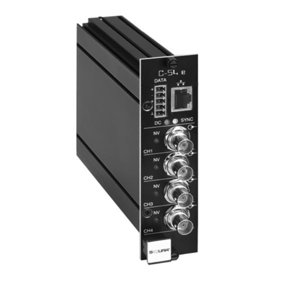
Models The C-54 E is to be used in MC 11 or similar power supply cabinets from Optelecom-NKF, but is also available as a stand-alone module (/SA version). Network connections are electrical or optical (/SFP versions). Front panel LEDs indicate network status, stream status (sync), data activity, no video, and DC power. -
Page 12: Front Panel
Product Description 3.2. Front Panel Features and indications Table 3.1 lists the front panel features of the C-54 E, C-54 e as shown in figure 3.1. DATA Connector pin assignments are given in section 4.4. C-54 E ← VIDEO (4 BNC conn.) video input (RJ-45 socket or SFP) Ethernet I/O, electrical or fiber... -
Page 13: Technical Specifications: Power Requirements And Operating Temperatures
Product Description 3.3. Technical Specifications: Power Requirements and Operating Temperatures For a more complete set of specifications, consult our sales documentation. Electrical: Power supply voltage 11 – 19 VDC Input current 0.8 A maximum Power consumption Typical 7.5W IP version Maximum 9.1W Power consumption... -
Page 15: Installation
INSTALLATION 4.1. Powering the Device Rack-mount modules Insert the C-54 E into an Optelecom-NKF MC 10 or MC 11 power supply cabinet. Plug the cabinet power cord into a grounded mains socket. /SA modules The stand-alone version (/SA) of the C-54 E requires an external power supply adapter (12 VDC). -
Page 16: Connector Pin Assignments
Installation 4.4. Connector Pin Assignments Correctly connecting the + and - inputs and outputs on the C-54 E green mini Combicon connector to the inputs and outputs on other equipment such as cameras, for example, requires special attention! Do NOT reverse the wires. Make sure you connect the ‘plus’ signal lines on the codec to the like ‘plus’... -
Page 17: Updating Device Definitions
Installation 4.5. Updating Device Definitions If a network device, such as the C-54 E, is not supported by the Optelecom-NKF application software on your host PC, an update can be downloaded from www.optelecom-nkf.com. The Support section of the site offers EMX updates and SNM Plug-in updates. Install the EMX update first if you will be performing both update types. -
Page 19: Connections
Connections CONNECTIONS Before you can make any video and other signal connections, the factory-set IP address and subnet mask of the C-54 E must be changed to be compatible with the network segment the module will be used in. 5.1. Establishing a Network Connection The factory-set IP address of a C-54 E is in the 10.x.x.x range. - Page 20 Connections Step 1: Setting the host PC to the factory default subnet of the C-54 E To configure the network adapter on the host PC In the Control Panel, open (see figure 5.2). Network Connections Right-click the connection to be configured, and select Properties.
- Page 21 Connections In the Internet Protocol (TCP/IP) Properties dialog, click Use the following IP address Enter an IP address that will assign your PC to the same subnet as the C-54 E (i.e. within the 10.x.x.x range). Use 255.0.0.0 as a subnet mask. important To prevent conflicts, be sure to choose a unique IP address.
-
Page 22: Making Video And Data Connections
With the C-54 E’s IP connection established, video and data connections can be made. The most convenient way to do so is using the module’s internal web pages. For an elaborate description, see chapter 7. A separate application program, such as Optelecom-NKF’s MX Configuration Tool, can be used as well. - Page 23 Connections General procedure for making links In both connection methods mentioned above, making a unicast one-way link (video or data) from source to destination entails at least the following steps: In the transmitter, specify a destination IP address, and a destination port number. In a compatible receiver, specify the transmitter IP address (source) and the local input port number (= the destination port number mentioned above).
-
Page 25: Interfaces
For an elaborate description of the web user interface, refer to chapter 7. 6.2. MX/IP The proprietary Optelecom-NKF MX/IP protocol offers direct access to the module settings contained in the Management Information Base (MIB). The MIB, a list of variables stored inside the module, can be read and/or written with special MX software. -
Page 26: Snmp
TCP connection while the data flows via UDP. For more details on controlling C-54 E media streams through HTTP and RTSP, and a specification of the Siqura protocol and its parameters, refer to Optelecom-NKF’s Codec/Camera Programming Interface specification. You can download this document from the Optelecom-NKF website. - Page 27 Interfaces Figure 6.1 RTSP URL format please note The encoder should be enabled and set to the correct media type. RTSP is a streaming protocol taking care of stream control. It does not handle device configuration. The stream in figure 6.1 would be pulled from the encoder with the IP address 172.22.250.129, using video input 1, media subtype MPEG-4, and logical encoder 1.
-
Page 29: Using The Internal Web
Using the internal web pages USING THE INTERNAL WEB PAGES The C-54 E web pages offer a user-friendly interface for configuring module settings and viewing live video images over the network. 7.1. System Requirements A PC with a standard web browser installed. An IP connection between the PC and the C-54 E (see section 5.1). - Page 30 Using the internal web pages In the Connect dialog box (figure 7.3), log in as either root or admin with an empty password (default login). Click or press ENTER. Figure 7.3 Connect box Upon successful login, the Live Video page (figure 7.5), the homepage of the module, displays.
-
Page 31: Web
Using the internal web pages 7.3. Web Page Features Menu Using the menu in the top left corner of each page you can navigate to the other web pages. Options in this menu are determined by the access level granted to the user's account. There are three account types: Admin, Operator, and Viewer. -
Page 32: Live Video
Using the internal web pages 7.4. Live Video Figure 7.5 Live Video page, Matrix mode On the Live Video page, the homepage of the C-54, you can view live video images from up to 4 connected cameras. Viewing mode Matrix mode The Live Video page opens in Matrix mode, offering an overview of the four video inputs. - Page 33 Using the internal web pages Figure 7.6 Live Video page, Maximized mode Encoder selection (Maximized mode) Encoder Allows you to select the video encoder of which you want to preview the encoding results: either Live View, Encoder 1, or Encoder 2. A selection you make here, applies to all four Video Inputs.
-
Page 34: Ptz Camera Input
Using the internal web pages 7.4.1. PTZ camera input Figure 7.8a Live Video page with PTZ control panel PTZ control A PTZ camera connected to the C-54 E and its internal MJPEG encoder can be controlled from the Live Video page. If PTZ settings have been configured correctly on the PTZ web page (see section 7.9) you can use the PTZ control panel appearing on the right of the preview in Maximized mode (figure 7.8a, b) to pan, tilt, zoom and focus the camera, control the iris, and define and recall preset camera positions. - Page 35 Using the internal web pages Zoom in Click arrows to pan and tilt the camera (at fixed speed) Zoom out Focus far Click ball to pan and tilt Focus near the camera (point of clicking determines pan/tilt speed) Iris open Iris close Figure 7.8b PTZ Control panel...
-
Page 36: Status
Using the internal web pages 7.5. Status Figure 7.9 Status page, Status tab: a snapshot with automatic page updating The Status page has two tabs: Status, and Measurements. 7.5.1. Status The Status tab (figure 7.9) provides information on the stream states of the video streams. The stream state of a signal stream is reported as Idle, Waiting, or Ok. -
Page 37: Measurements
Using the internal web pages 7.5.2. Measurements Figure 7.10 Status page, Measurements tab: a snapshot with automatic page updating The Measurements tab shows module temperatures (current and peak), module uptime, network specifics, such as the MAC address and the actual IP address, the network load from this module, the load information per processor, and signal stream-specific details. -
Page 38: Network
Using the internal web pages 7.6. Network Figure 7.11 Network page, basic (top) and advanced settings (bottom) IP settings On the Network page, you can set the IP address, subnet mask and gateway IP address. For correct functioning of the C-54 E, it is vital to set its network addressing to be compatible with the subnet it is hooked into. - Page 39 Using the internal web pages Advanced settings DHCP enable Allows a DHCP server to assign the IP address rather than using static IP addressing. Ethernet mode Transmission mode and speed. - Auto Autonegotiation (default). - 10 HDX Half duplex, 10 Mbit. - 10 FDX Full duplex, 10 Mbit.
-
Page 40: Video Input
Using the internal web pages 7.7. Video Input # Figure 7.12 General video settings, ‘Show Preview>>’ button pressed The first time you access a Video Input page, you may encounter a security alert concerning the installation of a Java update. This add-on, required for web pages to be displayed properly, does not give rise to any security risks. - Page 41 Using the internal web pages Video impedance Resistance to the flow of signal current. - 75 Ohm To be selected with one video source on one video input. - Hi-Z With a number of video inputs in parallel using one video source, use the Hi-Z setting on all inputs except the last.
-
Page 42: Encoder 1/2
Using the internal web pages 7.7.2. Encoder 1/2 Figure 7.13 Video Input1 page, Encoder 1 tab Encoder 1/2 settings Enable All encoders can be enabled and configured separately. Encoding mode The method used to compress the analog video input signal. MPEG-2, MPEG-4 or MJPEG. - Page 43 Using the internal web pages Video bit rate Controls variations in bit rates. For a concise explanation, consult the mode note on encoder settings below. MPEG-4 encoding mode supports the following bit rate modes. - Constant quality Keeps image quality constant at the cost of varying network load.
- Page 44 Using the internal web pages Bit rate Range: [10…15000]. Selecting a profile (see below), automatically sets the bit rate associated with the profile. Quality Setting available in MJPEG encoding mode. Reflects the amount of compression. For instance, 80% picture quality equals 20% compression. Profile Preset combinations of settings for specific purposes.
- Page 45 Using the internal web pages Note on encoder settings: Video bit rate mode can be set to be constant (i.e. the number of bits in a group of pictures) or variable. Selecting the correct mode for a given application, with emphasis on a good compromise between detail and good representation of frequent changes (motion), is generally vital.
- Page 46 Using the internal web pages Advanced settings If in doubt about these settings, do NOT change the default values. Encoder settings Figure 7.16a Advanced section, Encoder Figure 7.16b Advanced section, Encoder settings, MPEG-2 encoding settings, MPEG-4 encoding The settings available for configuration are determined by the selected encoding mode. Settings you can configure for MJPEG encoding, for instance, are: Frame rate divider, X-/Y- resolution, and De-interlacing.
- Page 47 Using the internal web pages Quantization matrix Available matrixes include MPEG Default, Alternative 1, and Alternative 2 Note on quantization: Quantization is a lossy compression technique used in image processing. It is based on the fact that variations in high frequency brightness, for example, are not easily distinguished by the human eye.
- Page 48 RTP session that can be used to control the session. Stream type The ES + UDP + RTP + NKF option will add an extended RTP header for Optelecom-NKF applications requiring extra information. RTP type This setting is NOT to be changed. Link lost alarm [1…1000] s.
- Page 49 Using the internal web pages Note on FloodGuard: FloodGuard is a stream control mechanism that can be enabled/disabled independently for each video and sampled data transmitter. FloodGuard will throttle the transmitter when it no longer receives control messages from the receiver, thereby preventing the transmitter from flooding the network.
- Page 50 Using the internal web pages RTSP Transmitter Figure 7.20 RTSP Transmitter settings DSCP field [0…63]. For details, see Transmitter # settings. Default multicast IP Destination IP address for multicast sessions. address Default multicast Port number for multicast sessions. port SAP settings Figure 7.21 SAP settings The C-54 E includes a SAP announcer.
- Page 51 Using the internal web pages Session scope Global, the default session scope, sets the Multicast IP range parameter to 224.2.128.0-224.2.255.255 (IPv4 global scope sessions). A SAP listening application will recognize the global scope and automatically listen for SAP announcements at the 224.2.127.254 multicast IP address.
- Page 52 Using the internal web pages Figure 7.22 Example settings SAP In VLC Media Player (v0.9.8a): In the Playlist menu, click , and select Additional Sources SAP Announcements Figure 7.23 Enabling SAP Announcements in VLC v0.9.8a In the Playlist menu, click Show Playlist The Playlist window displays (figure 7.24).
- Page 53 Using the internal web pages The video images are displayed in the media player. Figure 7.25 C-54 E multicast stream viewed in VLC - 49 -...
-
Page 54: Live View Encoder
Using the internal web pages 7.7.3. Live View Encoder Figure 7.26 Video Input1 page, Live View Encoder tab The C-54 E can stream MJPEG over UDP and HTTP. To transport MJPEG over HTTP and/or to use the Live View previews in the web pages, enable the Live View Encoder and configure its settings. - Page 55 Using the internal web pages Advanced settings Figure 7.27 Live View Encoder, Advanced settings Frame rate divider Relates to the frame rate configured in the encoder settings section. X- and Y-resolution Enable you to freely set picture resolution, instead of using the presets in the Encoder settings section.
-
Page 56: Osd (On Screen Display)
Using the internal web pages 7.7.4. OSD (On Screen Display) Figure 7.28 Video Input2 page, OSD tab The C-54 E features programmable on-screen display facilities. One graphic and up to three OSD bars can be displayed, each of which can be independently configured. Visual feedback is provided in the preview. - Page 57 Using the internal web pages Figure 7.30 Measurements available for OSD Figure 7.29 Date & Time formats Text # tab Figure 7.31 Text 1 tab with 3 OSD bars in the preview. Render modes: ‘Outline’ (top left & right) and ‘Border’ (bottom). Text colour/ Border/ Changes you make here (and in the other fields in this section) will outline colour...
- Page 58 The first time you access Advanced OSD settings after opening your web browser, you are asked to authenticate. Next, a security alert will display. Using the Font management feature requires Java Runtime Environment 1.6 or higher. The Optelecom-NKF application does not give rise to any security risks. You can run it safely.
- Page 59 Using the internal web pages Figure 7.34 Selecting a font To remove a font Log on to Font management as root or admin. In the Font management section (see figure 7.33), select the font. Click the button. Graphics tab Figure 7.35 Graphics tab with 3 OSD bars and a graphic (top left) in the preview The Graphics tab enables you to upload graphics (see Graphic management), and scale and position a selected graphic on your screen.
- Page 60 Using the internal web pages Advanced picture settings Figure 7.36 Graphics tab, Advanced picture settings X- and Y-Position Enable you to position the graphic relative to the anchor point. anchor point Animation speed Enables you to set the speed for an animated GIF graphic. scaling factor Graphic management To upload a graphic to the module...
-
Page 61: Vmd (Video Motion Detection)
Using the internal web pages 7.7.5. VMD (Video Motion Detection) To be able to use the VMD facilities from this web page: An ActiveX component supporting video overlays needs to be installed. Also, to use this component successfully, the internet settings on the machine running the web pages must be adapted to have the C-54 E accepted as a trusted site and to allow ‘unsafe’... - Page 62 Using the internal web pages 7.7.5.2 VMD Configuration 1: Detection parameters Figure 7.40a Video page, VMD tab, VMD disabled Figure 7.40b Configuration section with controls, video picture and video motion detection inset, the latter with mask applied (see below). The mask permits motion detection in the right half of the picture only, at the top of the stairs, so passers-by and cars would not be registered by this detector facility;...
- Page 63 VMD alarm. The level of this alarm can be set (A-N) using separate Optelecom-NKF software. VMD response Fast or Filtered. Filtering is used to suppress a single peak as false triggering.
- Page 64 Using the internal web pages Figure 7.42a Full (0% transparency) mask over left part of screen. Only motion at the door (rightmost half of the picture) will be detected. The locally reduced motion level (in each element) registered may also sink under the sensitivity level set;...
- Page 65 Using the internal web pages The white block pattern indicates changes in the image. System noise can be removed by lowering sensitivity until the white blocks vanish, as is the case with a still image. Figure 7.43a (left), b (right) VMD detection windows, with mask applied to the left half of the window.
- Page 66 Using the internal web pages Note on Advanced VMD settings: Motion is detected by comparing the current frame with a reference image (e.g. a previous frame) and calculating the difference between the two. The value you enter for the Event window size parameter determines how many frames are evaluated for VMD purposes at a time.
-
Page 67: Data Rs-422/485
Using the internal web pages 7.8. Data RS-422/485 Figure 7.46 Data RS-422/485 page. Transmitter and receiver can be configured in the usual manner. General settings Figure 7.47 Wire mode selection Wire mode RS-422, RS-485 (2-wire), RS-485 (4-wire). The RS-4xx interface type available on the 5-pin mini Combicon connector marked DATA is set in software. - Page 68 Using the internal web pages UART settings Figure 7.48 UART settings. Right: selectable speeds. The C-54 E uses a UART (Universal Asynchronous Transmitter/Receiver) for data transmission. The UART will recognize and reproduce the words in the data stream. This is only possible if the UART is programmed to understand the serial data format.
- Page 69 Using the internal web pages TCP server settings Figure 7.50 TCP server settings Server Enable Selecting the check box will enable the streaming of UART data over TCP using a client/server connection. The server accepts requests from a specific client, or any host if not specified. Server port [0…65535].
- Page 70 Stream type UDP, UDP + NKF. The UDP + NKF option will add an extended RTP header for Optelecom-NKF applications requiring extra information. Link lost alarm [1…1000] s. Time in seconds before alarm sent; default=10s.
- Page 71 FloodGuard tx interval [1…1000] ms. Stream type UDP, UDP + NKF. The UDP + NKF option will add an extended RTP header for Optelecom-NKF applications requiring extra information. Link lost alarm timeout [1…1000] s. Time in seconds before alarm sent; default=10s.
-
Page 72: Ptz
The first time you access the PTZ web page after opening your web browser, you are asked to authenticate. Next, a security alert will display. Using the PTZ page requires Java Runtime Environment 1.6 or higher. The Optelecom-NKF application does not give rise to any security risks. You can run it safely. - Page 73 Using the internal web pages To upload a PTZ driver In the PTZ driver management section, log in as admin or root. Click Browse The Open dialog box displays. Browse to the folder containing the driver. Select the correct file (.txt extension), and then click Open The driver displays in the File textbox.
- Page 74 Using the internal web pages To remove a driver In the PTZ driver management section (see figure 7.54), log in as admin or root. Select the driver. Click the button. Data settings Figure 7.57 PTZ page, data settings Bit rate 1200, 2400, 4800, 9600, 19200, 38400, 57600, 115200 bit/s Word length 5, 6, 7, 8...
-
Page 75: Device Management
Using the internal web pages 7.10. Device Management Figure 7.59 Device Management page, General tab The Device Management page has six tabs: General, SNMP, MX, Auto Discovery, Firmware, and Reboot. 7.10.1. General Identification This section offers administrative module information. Device name This section contains label settings, which can be edited and saved. -
Page 76: Snmp
To prepare a C-54 Encoder for SNMP management, the database documenting the C-54 E variables that can be read or modified must be registered with the program; such SNMP MIB documents (indicated OPTC) are available from Optelecom-NKF or from its website. SNMP system information The SNMP System Information section (figure 7.62) shows the network/device data... - Page 77 Using the internal web pages SNMP communities The community strings (names which can be regarded as passwords) in the SNMP Communities section must conform to those configured in the SNMP manager. Often, these are ‘public’, mainly used for the read and trap communities, and ‘private’ or ‘netman’, for read-write operations.
- Page 78 7.10.3. Figure 7.64 Device Management, MX tab MX/IP (see also section 6.2) is a UDP protocol used to communicate with Optelecom-NKF equipment over a network connection. Optelecom-NKF application software, such as Operator Storage, Operator Office, the MX Software Development Kit, and MX Configuration Toolkit use the MX/IP protocol to access, configure, control and manage Optelecom-NKF network devices.
-
Page 79: Auto Discovery
Using the internal web pages 7.10.4. Auto Discovery Figure 7.65 Device Management, Auto Discovery On the Auto Discovery tab you can enable UPnP (Universal Plug and Play). If enabled, UPnP will allow the C-54 E to advertise its presence and services to control points on the network. A control point can be a network device with embedded UPnP, a VMS application or a spy software tool (e.g. - Page 80 Using the internal web pages Figure 7.66 C-54 E device description in Intel Device Spy tool To view the device description in XML Right-click the C-54 E entry in the left-hand panel. From the context menu, select Get Device XML The XML device description is displayed in your web browser.
-
Page 81: Firmware
The first time you access the Firmware tab after opening your web browser, you are asked to authenticate. Next, a security alert displays. Using the C-54 E firmware upgrade feature requires running an Optelecom-NKF application. The application does not give rise to any security risks and can be run safely. - Page 82 Using the internal web pages To upgrade the firmware In the Upgrade section, click Browse The Open dialog box displays. Browse to the folder containing the firmware image. Select the correct file (.nkffw extension), and then click Open Figure 7.69 Selecting the firmware image file The corresponding Article Code and Software version appear in the Upgrade section.
-
Page 83: Reboot
Using the internal web pages 7.10.6. Reboot Figure 7.71 Device Management page, Reboot Reboot Reboot Reboots the module without resetting variables. Reset to factory Reset option for all variables that can be set by the user, with the settings: keep exception of the network settings. -
Page 84: User Management
Using the internal web pages 7.11. User Management Figure 7.72 User Management page, Web Access tab The User Management page is available to users with an Admin account. It has two tabs: Web Access and Linux. 7.11.1. Web Access The C-54 E has three levels of access to the internal web pages. User groups are: Administrators, Operators, and Viewers. -
Page 85: Linux
Using the internal web pages To delete a user Select the user name from the User list, and then click Remove To confirm the deletion, press 7.11.2. Linux Figure 7.75 User Management page, Linux tab Using the Linux tab the Admin can change the existing password to the root account. The root password is required when logging on to Linux with root access rights. -
Page 86: Date & Time
Using the internal web pages 7.12. Date & Time Figure 7.76 Date and time settings The C-54 E has a battery-supported real-time clock that can be adjusted either manually (as shown in figure 7.76), or automatically with the aid of an SNTP (Simple Network Time Protocol) server. -
Page 87: Appendix 1 - Multicasting, Multi-Unicasting, Port Numbers
Appendix 1: Multicasting, Multi-unicasting, Port numbers APPENDIX 1 – MULTICASTING, MULTI-UNICASTING, PORT NUMBERS Multicasting The C-54 E system can be used in a multicasting setting. The network switches and other devices used must be carefully configured for, and capable of, handling multicasting and its associated protocols (most notably IGMP v2). - Page 88 10000-65535 are generally safe. Default port numbers (used by receivers) are shown in table A1.1: General Example Video: 50xxx Video: 50010 Data: 52xxx Data 1: 52010 (RS-4xx) Table A1.1 Default port numbers Optelecom-NKF MX applications using automatic port number allocation may use 55000 and - 84 -...
-
Page 89: Appendix 2 - Mpeg-4 Video Plug-In Installation
The C-54 E Video Motion Detection web page has a live video overlay on which masks can be drawn. To use the overlay, the MPEG-4 Video Plug-in ActiveX control must be installed from your C-54 E CD. Check the Optelecom-NKF website for the most recent version. To install the Video Plug-in In the root folder of your CD, double-click the Showroom.exe file. - Page 90 Appendix 2: MPEG-4 Video Plugin installation Figure A2.2 IP range 172.22.250.* added to the Trusted Sites Configuring IE7 requires an additional step. On the Security tab, with the Trusted sites icon selected, click Default level Move the slider down and set the level to (figure A2.3).
-
Page 91: Appendix 3 - Enabling Javascript
Appendix 3: Enabling JavaScript APPENDIX 3 – ENABLING JAVASCRIPT In order for the C-54 E web pages to display correctly, JavaScript must be enabled in your web browser. To enable JavaScript in Internet Explorer From Internet Explorer's Tools menu, select Internet Options On the Security tab, click the Internet globe icon, and then click Custom level... -
Page 93: Appendix 4 - Video Player Plug-In Installation
Appendix 4 – Video Player Plugin Installation APPENDIX 4 – VIDEO PLAYER PLUG-IN INSTALLATION Displaying video images in the web pages requires a video player plug-in. The C-54 E supports QuickTime and VLC. If neither of these is detected when attempting to display a video stream, you will be offered links to download locations. - Page 94 Appendix 4 – Video Player Plugin Installation VLC and Windows Vista Configure the following settings in the VLC media player when running this plug-in on a Windows Vista PC. Open the VLC media player. From the Settings menu, select Preferences In the lower right corner, select the check box.
- Page 96 © Optelecom-NKF B.V. 2009 *%199925411050-00%* Version 1.0 (092201-1) C54E-MC v2.0 - UM (MW03SP3)
Need help?
Do you have a question about the Siqura C-54 E-MC and is the answer not in the manual?
Questions and answers