Table of Contents
Advertisement
Quick Links
Download this manual
See also:
User Manual
Advertisement
Table of Contents

Related Manuals for IBM totalstorage 2109 M12


Summary of Contents for IBM totalstorage 2109 M12
- Page 1 IBM TotalStorage SAN Switch 2109 Model M12 Installation and Service Guide Read Before Using This product contains software that is licensed under written license agreements. Your use of such software is subject to the license agreements under which they are provided.
- Page 3 IBM TotalStorage SAN Switch 2109 Model M12 Installation and Service Guide GC26-7633-00...
- Page 4 Order publications through your IBM representative or the IBM branch office serving your locality. © Copyright International Business Machines Corporation 2004. All rights reserved.
-
Page 5: Table Of Contents
Turning the switch on and off ....15 Switch components ..... . 15 © Copyright IBM Corp. 2004... - Page 6 Removing and replacing a power supply or filler panel ..75 Time required ......75 IBM TotalStorage SAN Switch: 2109 Model M12 Installation and Service Guide...
- Page 7 Removing a power supply or filler panel ....75 Replacing a power supply or filler panel ....77 Removing and replacing a blower assembly .
- Page 8 Index ......119 IBM TotalStorage SAN Switch: 2109 Model M12 Installation and Service Guide...
-
Page 9: Figures
42. Cable management tray ......80 43. 2109 Model M12 with the cable management tray ....81 © Copyright IBM Corp. 2004... - Page 10 IBM TotalStorage SAN Switch: 2109 Model M12 Installation and Service Guide...
-
Page 11: Tables
Tables 1. Brocade and IBM product and model number matrix ....xxvi 2. Configuration parameters ......9 3. - Page 12 IBM TotalStorage SAN Switch: 2109 Model M12 Installation and Service Guide...
-
Page 13: Safety And Environmental Notices
(D004), at the end of each notice. Use this ID to locate the translation of ® ™ these danger and caution notices in the IBM eServer Safety Notices (G229–9054) publication, which is on the CD-ROM that accompanies this product. - Page 14 1. Turn everything OFF (unless instructed otherwise). 2. Attach all cables to devices. 3. Attach signal cables to connectors. 4. Attach power cords to outlet. 5. Turn device ON. (D005) IBM TotalStorage SAN Switch: 2109 Model M12 Installation and Service Guide...
-
Page 15: Labels
Labels As an added precaution, safety labels are often installed directly on products or product components to warn of potential hazards. The actual product safety labels may differ from these sample safety labels: DANGER Hazardous voltage, current, or energy levels are present inside any component that has this label attached. -
Page 16: Attention Notices
The cover should be kept on the serial port whenever it is not being used. 7. Correct any problems that you find. Internal machine checks Perform the following internal machine checks: IBM TotalStorage SAN Switch: 2109 Model M12 Installation and Service Guide... -
Page 17: Safety Label Checks
1. Check for any non-IBM changes that might have been made to the machine. If any are present, obtain the “Non-IBM Alteration Attachment Survey” form, number R009, from the IBM branch office. Complete the form and return it to the branch office. -
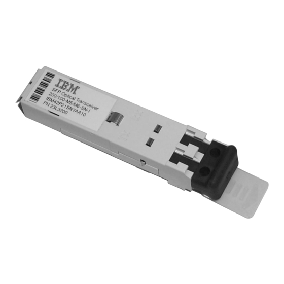
Page 18: Heavy Load Label
Note: The following SFP illustrations may differ from the SFPs included or installed with your particular switch, depending upon the SFP manufacturer. The labels shown below may vary by manufacturer. IBM TotalStorage SAN Switch: 2109 Model M12 Installation and Service Guide... - Page 19 SJ000317 Figure 6. SFP label (front view) SJ000314 Figure 7. SFP label (back view) xvii Safety and environmental notices...
-
Page 20: Ac Grounding
Perform the following safety label checks for the bridge tool: 1. Verify that the bridge tool alignment label shown in Figure 8 on page xix is installed on the load plate. xviii IBM TotalStorage SAN Switch: 2109 Model M12 Installation and Service Guide... -
Page 21: Bridge Tool Alignment Label
ALINHAR A PLACA DE CARREGAMENTO (P/N 11P4369) COM A LINHA ANTES DE MOVER A CHAVE OU O CHASSI DA CHAVE PARA DENTRO OU FORA DO GABINETE ALLINEARE LA PIASTRA DI CARICO (P/N 11P4369) E LA RIGA PRIMA DI SPOSTARE L’INTERRUTTORE O IL TELAIO DELL’INTERRUTTORE ALL’INTERNO O ALL’ESTERNO DELL’ARMADIETTO SJ000749... -
Page 22: Tilt Warning Label
SJ000751 Figure 10. Genie tool and load plate label 4. Verify that the pinch point label shown in Figure 11 on page xxi is installed on the load plate. IBM TotalStorage SAN Switch: 2109 Model M12 Installation and Service Guide... -
Page 23: Laser Safety
P/N 18P5850-B SJ000752 Figure 11. Pinch point label Laser safety This equipment contains Class 1 laser products, and complies with FDA radiation Performance Standards, 21 CFR Subchapter J and the international laser safety standard IEC 825-2. CAUTION: This product contains a Class 1M laser. Do not view directly with optical instruments. -
Page 24: Rack Safety
Attempting to move the drawer partially or completely out of the rack may cause the rack to become unstable or cause the drawer to fall out of the rack. (R001) xxii IBM TotalStorage SAN Switch: 2109 Model M12 Installation and Service Guide... -
Page 25: Rack Relocation (19" Rack)
Rack Relocation (19″ Rack) CAUTION: Removing components from the upper positions in the rack cabinet improves rack stability during relocation. Follow these general guidelines whenever you relocate a populated rack cabinet within a room or building: v Reduce the weight of the rack cabinet by removing equipment starting at the top of the rack cabinet. -
Page 26: Environmental Notices And Statements
Because IBM does not test any equipment for compatibility with fire suppression systems, IBM does not make compatibility claims of any kind nor does IBM provide recommendations on fire suppression systems. -
Page 27: About This Document
The following documents contain information related to this product: v IBM TotalStorage SAN Switch 2109 Model M12 Installation and Service Guide, GC26-7633 (this document) v IBM TotalStorage SAN Switch 2109 Model M12 and Model M14 User’s Guide, GC26-7636 v IBM eServer Safety Notices, G229–9054 v IBM TotalStorage SAN Switch Statement of Limited Warranty, GC26–7638... -
Page 28: Web Sites
When you use any of the Brocade documents, you will notice that the model numbers reflect the original Brocade switches. Table 1 provides a product matrix for you to use to correlate the Brocade model numbers to the IBM product and model numbers. -
Page 29: Getting Help
Department GZW 9000 South Rita Road Tucson, Arizona 85744–0001 U.S.A. When you send information to IBM, you grant IBM a nonexclusive right to use or distribute the information in any way it believes appropriate without incurring any obligation to you. - Page 30 IBM TotalStorage SAN Switch: 2109 Model M12 Installation and Service Guide...
-
Page 31: Chapter 1. Introduction
Chapter 1. Introduction This chapter introduces the IBM TotalStorage SAN Switch 2109 Model M12 switch (hereafter referred to as the Model M12 or the M12) and contains the following information: v “Overview” v “Monitoring and managing the M12” on page 4... -
Page 32: Port Side Of Chassis
The 16-port cards, which contain 16 fibre channel SFP ports v Two CP cards, each with a modem serial port, a terminal serial port, and 10 Mbps or 100 Mbps Ethernet port IBM TotalStorage SAN Switch: 2109 Model M12 Installation and Service Guide... -
Page 33: Blower Assembly Side Of Chassis
v Four power supplies that are hot swappable and have built-in fans v Two ac power connectors. Each ac power connector has an on or off ac power switch Power Slot Supply 4 Exhaust Vent Power Supply 3 CP Card Link Link 10/100 Mb/s... -
Page 34: Monitoring And Managing The M12
POST, see “Interpreting POST” on page 30. The Model M12 is compatible with the following management interfaces: v Command line interface through a Telnet connection v Fabric Manager IBM TotalStorage SAN Switch: 2109 Model M12 Installation and Service Guide... - Page 35 v Web Tools v SNMP applications v Management server For more information about these management interfaces, see the Brocade Fabric Manager User’s Guide and the Brocade Advanced Web Tools User’s Guide. Chapter 1. Introduction...
- Page 36 IBM TotalStorage SAN Switch: 2109 Model M12 Installation and Service Guide...
-
Page 37: Chapter 2. Starting And Configuring The M12
CP card, see the Brocade Fabric OS Reference. Note: You should routinely back up the configuration to ensure that the current configuration is available if needed. © Copyright IBM Corp. 2004... -
Page 38: Items Required
16–port cards in slots 1–4, and “switch 1”, which contains any 16–port cards in slots 7–10. The default logical IP addresses are as follows: – 10.77.77.77 sw0 – 10.77.77.76 sw1 IBM TotalStorage SAN Switch: 2109 Model M12 Installation and Service Guide... -
Page 39: Configuration Procedure
v Two switch names, if the default switch names are not going to be used. Switch names can be up to 15 characters long. Switch names can include alphabetical, numerical, and underscore characters, and must begin with an alphabetical character. The default switch name for the logical switches is: –... - Page 40 If you change the IP address, you can cause a domain address format registered state change notification (RSCN) to be issued. a. To configure the first logical IP address, type the following command at the prompt: IBM TotalStorage SAN Switch: 2109 Model M12 Installation and Service Guide...
- Page 41 ipAddrSet 0 b. Type the requested information for this IP address at the prompt: Ethernet IP Address [10.77.77.77]: Ethernet Subnetmask [0.0.0.0]: Fibre Channel IP Address [none]: Fibre Channel Subnet Mask [none]: The logical IP address is updated immediately. c. To configure the second logical IP address, type the following command at the prompt: ipAddrSet 1 d.
- Page 42 The ports and cables that are used in trunking groups must meet specific requirements. For a list of these requirements, see the IBM TotalStorage SAN Switch 2109 Model M12 User’s Guide and the Brocade ISL Trunking User’s Guide.
- Page 43 Note: Cables are keyed so that you can only insert them with the correct orientation. If a cable does not slide in easily, ensure that it is correctly oriented. c. Repeat step 11a on page 12 and step 11b on page 12 for the remaining ports.
- Page 44 IBM TotalStorage SAN Switch: 2109 Model M12 Installation and Service Guide...
-
Page 45: Chapter 3. Operating The M12
To ensure correct cooling of the chassis and protection from dust, install a filler panel in any slots that do not contain a 16–port card. Disassembling any part of a 16–port card voids the part warranty and regulatory certifications. © Copyright IBM Corp. 2004... -
Page 46: Control Processor Cards
For information about commands and whether you can enter them through the active or standby CP card, see the Brocade Fabric OS Reference. Each CP card provides the following ports: v Modem serial port IBM TotalStorage SAN Switch: 2109 Model M12 Installation and Service Guide... -
Page 47: Power Supplies
The modem serial port has an RS–232 connector that is wired as a data terminal equipment (DTE) device. It is designed to connect to a distributed computing environment (DCE) device, such as a modem. v Terminal serial port (also known as a console port) The terminal serial port has an RS–232 signal subset connector that you can use to connect to a PC serial port or dumb terminal. -
Page 48: Ac Power Input Connectors And Ac Power Switches (Circuit Breaker)
To ensure continuous adequate cooling, maintain three operating blower assemblies at all times except for the brief period when replacing a blower assembly. The 16–port cards automatically shut down if the temperature range is exceeded. IBM TotalStorage SAN Switch: 2109 Model M12 Installation and Service Guide... -
Page 49: Wwn Card And Bezel
Attention: Disassembling any part of the blower assembly voids the part warranty and regulatory certifications. CAUTION: No user-serviceable parts are inside the blower assembly. Perform the following steps to determine the status of a blower assembly: 1. Check the LEDs on the blower assembly. 2. -
Page 50: Interpreting Led Activity
Note: The LED patterns can temporarily change during a POST and other diagnostic tests. Figure 14 on page 21 shows the location of the LEDs on the 16–port card. IBM TotalStorage SAN Switch: 2109 Model M12 Installation and Service Guide... -
Page 51: Port Card Leds
Power LED Direction to Push Yellow Ejector Button Status LED Port (16x) Port Speed LED (16x) Port Status LED (16x) Ejector (2x) Direction to Push Yellow Ejector Button SJ000637 Figure 14. 16–port card LEDs Chapter 3. Operating the M12... - Page 52 Brocade Fabric OS power. Procedures Guide. Steady green The port is set to 2 No action is required. Gbps mode. IBM TotalStorage SAN Switch: 2109 Model M12 Installation and Service Guide...
- Page 53 Table 3. 16–port card LED patterns (continued) Name of LED Location of LED Color of LED Status of hardware Action Port Status and To the left of No light (LED is off) Verify that the Power LED v Either the 16–port Activity each port, below is lit and check the...
-
Page 54: Leds On The Cp Card
Status LED 10101 Console Port Link Status LED Ethernet Port Link Speed LED 10/100 Mb/s Ejector (2x) Direction to Push Yellow Ejector Button SJ000638 Figure 15. CP card LEDs IBM TotalStorage SAN Switch: 2109 Model M12 Installation and Service Guide... - Page 55 Steady yellow The CP card is faulty. Ensure that the CP card is firmly seated. If the LED still displays yellow, contact IBM. Slow-flashing yellow (on The CP card is not Pull the CP card out and 2 seconds; off 2 seated correctly, or is reseat it.
-
Page 56: Leds On The Power Supply
LED. It also lists the status of the switch that is associated with each LED color and action that you can take in response to that status. IBM TotalStorage SAN Switch: 2109 Model M12 Installation and Service Guide... -
Page 57: Power Supply Led Patterns
Table 5. Power supply LED patterns Name of LED Location of LED Color of LED Status of hardware Action Power Uppermost LED No light (LED is off) The power supply does Ensure the following states: not have incoming v The power supply is power. -
Page 58: Leds On The Blower Assembly
Steady green The blower assembly No action is required. has incoming power. IBM TotalStorage SAN Switch: 2109 Model M12 Installation and Service Guide... -
Page 59: Leds On The Wwn Card And Bezel
Table 6. Blower assembly LED patterns (continued) Name of LED Location of LED Color of LED Status of hardware Action Fault Above and to the No light (LED is off) The blower assembly Ensure that the blower right of the blower is either healthy or assembly has incoming assembly handle... -
Page 60: Interpreting Post
3. Analyzes the fabric. If any ports connect to other fabric elements (switches), the switch participates in a fabric configuration. 4. Obtains a domain ID and assigns port addresses. 5. Constructs unicast routing tables. 6. Enables normal port operation. IBM TotalStorage SAN Switch: 2109 Model M12 Installation and Service Guide... -
Page 61: Maintaining The Switch
2. Verify that the switch prompt displays when a POST completes. If it does not display, a POST did not successfully complete. Contact IBM for support. 3. Review the system log. Any errors that are detected during a POST are written to the system log. - Page 62 IBM TotalStorage SAN Switch: 2109 Model M12 Installation and Service Guide...
-
Page 63: Chapter 4. Installing Modems
For security reasons, the modem session is automatically disconnected if the modem cable is detached while a session is active. Figure 19 on page 34 shows two modems that are connected to a switch. © Copyright IBM Corp. 2004... -
Page 64: Setting Up A Remote Modem System (Optional)
3. Start the terminal emulator application and if needed, configure as follows: v Enter the parameters in Table 7 on page 35 for Windows 95, 98, 2000, ME, or NT, or TERM in a UNIX environment. IBM TotalStorage SAN Switch: 2109 Model M12 Installation and Service Guide... -
Page 65: Installing The Modems On The Switch
Table 7. Modem parameters for Windows 95, 98, 2000, ME, or NT, or TERM in a UNIX environment Parameter Value Port speed (bits per second) 115200. This value usually defaults to the highest speed that the modem supports and then possibly negotiates for a slower speed. Data protocol Standard EC Compression... -
Page 66: Verifying Modem Installation
CP card is being logged into. Login normally, if desired, or disconnect the session. 14. Restore the Telco connector to the active CP card modem. IBM TotalStorage SAN Switch: 2109 Model M12 Installation and Service Guide... - Page 67 The switch modems are now ready to use. Notes: 1. Experienced users can use the haFailover command to further evaluate the attached modems. It is important to wait approximately 5 minutes after a failover (or restart) to allow the system to correctly set up the modems. 2.
- Page 68 IBM TotalStorage SAN Switch: 2109 Model M12 Installation and Service Guide...
-
Page 69: Chapter 5. Installing And Removing Model M12 Switches
– Routing the cables through the cable channels on the sides of the cabinet – Using the patch panels v Ensure that the power directors have two dedicated electrical branch circuits with the following characteristics available for use: – 200–40 V ac, 30 amps – 50–60 Hz © Copyright IBM Corp. 2004... -
Page 70: Ordering The Lift Tool
24–inch load plate. Use the following part numbers when you order: v Lift tool: PN 09P2481 v 24–inch load plate: PN 11P4369 IBM TotalStorage SAN Switch: 2109 Model M12 Installation and Service Guide... -
Page 71: 2109 Model M12 Standard Shipment
– The 14U chassis mount kit with installation instructions – Bridge tool: PN 18P5855 Note: You can order SFP transceivers separately from IBM. The 2109 Model M12 supports both SWL and LWL transceivers. Chapter 5. Installing and removing Model M12 switches... -
Page 72: Unpacking The M12
Figure 20. 2109 Model M12 on a pallet Attention: Remove the chassis door before you move the chassis. 5. Remove the chassis door from the chassis. a. Open the door 90°. IBM TotalStorage SAN Switch: 2109 Model M12 Installation and Service Guide... -
Page 73: Installing An Additional M12 In A Cabinet
b. Support the door to prevent it from falling. Pull the door away from the chassis. c. Push the spring-loaded lever on the upper hinge up and into the notch in the hinge. See Figure 21. d. Push the spring-loaded lever on the lower hinge down and into the notch in the hinge. - Page 74 Attach the shelf brackets to the cabinet rails, by using six 1/4–20 x 1/2-in. Phillips panhead screws with lock washers per bracket. Tighten the screws. See Figure 23 on page 45. IBM TotalStorage SAN Switch: 2109 Model M12 Installation and Service Guide...
- Page 75 Adjusting Screws Shelf Bracket (2x), Notched End SJ000663 Figure 23. Shelf brackets are installed on the rails (cabinet walls are not shown) 3. Tighten the adjusting screws on the shelf brackets. 4. Attach four 10–32 clip nuts to the two rails at the front of the cabinet (service aisle side).
- Page 76 Phillips-flathead screws (item 5) per bracket. Tighten the screws. Orient the slotted holes in the brackets towards the blower side of the chassis. See Figure 25 on page 47 for orientation. IBM TotalStorage SAN Switch: 2109 Model M12 Installation and Service Guide...
- Page 77 Flat Upper Rack Mount Bracket (2x) Disconnected L-shaped (Items 3a and 4a) Bracket (2x) (Items 3b and 4b) 10-32 Screws (8x) (Item 5) SJ000665 Figure 25. Attaching the right and left flat upper mount brackets to the chassis 7. Attach the two L-shaped upper mount brackets (items 3b and 4b) to the cabinet rails.
-
Page 78: Using The Lift Tool, The 24-Inch Load Plate, And The Bridge Tool
6. If the load platform is not at its lowest position, lower the load platform to its lowest position. 7. Move the lift tool to a position near the rear of the cabinet. See Figure 27 on page 49. IBM TotalStorage SAN Switch: 2109 Model M12 Installation and Service Guide... - Page 79 Rear SJ000682 Figure 27. Rear view of cabinet and lift tool Note: If you are passing through a narrow passage or door, it might be necessary to rotate the drawer on the load platform. 8. Set the wheel brake by pressing down on the wheel brake pedal. 9.
- Page 80 Align the two-pin section of the support on the front of the vertical rail with the bottom hole and the middle hole in EIA unit 20. IBM TotalStorage SAN Switch: 2109 Model M12 Installation and Service Guide...
- Page 81 d. Align the one-pin section of the support on the front of the vertical rail with the middle hole in EIA unit 18. 13. Turn the winch crank counterclockwise, 1/4 turn, to set the winch brake. 14. Set the wheel brake and place the wheel chocks around the wheels. 15.
- Page 82 Push the levers into the notches. b. Align the door hinges with the chassis portion of the hinges. c. Release the pins by pushing the levers out of the notches. IBM TotalStorage SAN Switch: 2109 Model M12 Installation and Service Guide...
-
Page 83: Removing An M12 From The Cabinet
Upper Door Hinge Upper Door Hinge with Lever Chassis Portion of Hinge with Lever in Notch Out of Notch (Pin Released) SJ000661 Figure 31. Removing the chassis door 22. Uninstall the bridge tool and return it to its original box. Note: For turning on the power and for the configuration instructions, see Chapter 2, “Starting and configuring the M12,”... - Page 84 24-inch load plate with the line on the bridge tool. 12. Turn the winch crank counterclockwise 1/4 turn to set the winch brake. IBM TotalStorage SAN Switch: 2109 Model M12 Installation and Service Guide...
- Page 85 13. Set the wheel brake. Place the wheel chocks around the wheels. CAUTION: A fully populated 2109 Model M12 weighs approximately 115 kg (250 lbs) and requires a minimum of two people and a lift tool to install it. (C011) Before you install it, verify that the additional weight of the chassis does not exceed the cabinet’s weight limits or unbalance the cabinet.
- Page 86 IBM TotalStorage SAN Switch: 2109 Model M12 Installation and Service Guide...
-
Page 87: Chapter 6. Servicing The M12
It is the responsibility of the customer to ensure that the outlet is correctly wired and grounded to prevent an electrical shock. (D004) © Copyright IBM Corp. 2004... - Page 88 “Norway only:” This product is designed for an IT power system with phase-to-phase voltage of 230V. After operation of the protective device, the equipment is still under voltage if it is connected to an IT power system. IBM TotalStorage SAN Switch: 2109 Model M12 Installation and Service Guide...
-
Page 89: Power-Off Procedure
Power-off procedure Perform the following steps to power off the switch: 1. Open the rear door of the cabinet. Check the power cabling from the M12 that is attached to the PDU that you are servicing. These switches have dual power cords and are plugged into PDUs with independent ac sources. - Page 90 Yellow Ejector Button Status LED Port (16x) Port Speed LED (16x) Port Status LED (16x) Ejector (2x) Direction to Push Yellow Ejector Button SJ000637 Figure 32. 16–port card showing ejectors IBM TotalStorage SAN Switch: 2109 Model M12 Installation and Service Guide...
-
Page 91: Removing A Filler Panel
Removing a filler panel The switch accommodates the following two types of filler panels: v A filler panel with ejectors v A filler panel without ejectors Perform the following steps to remove a filler panel with ejectors: 1. Push the yellow tab in on each ejector. See Figure 33. 2. -
Page 92: Replacing A 16-Port Card Or Filler Panel
The levering action of the handles seats the 16–port card or filler panel in the slot. Figure 35 on page 63 shows the alignment guides in the card slots. IBM TotalStorage SAN Switch: 2109 Model M12 Installation and Service Guide... -
Page 93: Guidelines For Managing Cables
SJ000642 Figure 35. Alignment guides in the card slots Perform these additional steps if you are installing a new 16–port card: 1. Verify that the power LED on the 16–port card is displaying a steady green light (it might require a few seconds to turn on). If it does not turn on, ensure that the 16–port card has power and is firmly seated. -
Page 94: Removing And Replacing A Cp Card Or Filler Panel
Repair or disassemble Exchange only with the IBM-approved part. Recycle or discard the battery as instructed by local regulations. In the United States, IBM has a process for the collection of this battery. For information, call 1-800-426-4333. Have the IBM part number for the battery unit available when you call. -
Page 95: Confirming A Failed Cp Card
Confirming a failed CP card Before you replace the CP card, verify the necessity of the replacement. Any of the following events might indicate that a CP card is faulty: v The Status LED on the CP card is orange, or the Power LED is not lit. v The slotshow command does not show that the CP card is enabled. - Page 96 5. Run the version command to record the version of the active CP card. 6. Run the hadisable command from the active CP card to prevent failover or communication between the CP cards during the replacement. IBM TotalStorage SAN Switch: 2109 Model M12 Installation and Service Guide...
-
Page 97: Removing A Cp Card Or Filler Panel
7. From the serial console for the healthy (and active) CP card, back up the current configuration for logical switch 0. See the possible output from the configupload command in step 8. a. Run the configupload command. b. Enter the requested information at the prompts. 8. -
Page 98: Cp Card Showing Ejectors
1. Push in the yellow tab on each ejector. See Figure 37 on page 69. 2. Lever both ejectors all the way open. 3. Slide the filler panel out of the chassis. IBM TotalStorage SAN Switch: 2109 Model M12 Installation and Service Guide... -
Page 99: Replacing A Cp Card Or Filler Panel
Direction to Push Yellow Ejector Button Direction to Push Yellow Ejector Button SJ000643 Figure 37. CP card filler panel with two ejectors Replacing a CP card or filler panel Attention: Do not force the installation. If the CP card or filler panel does not slide in easily, ensure that it is correctly oriented and aligned in the rail guides before you continue. -
Page 100: Verifying The Operation Of The New Cp Card
From the serial console for the active CP card (the CP card that was not replaced), run the hashow command and verify that the command output includes HA Enabled Heartbeat Up. IBM TotalStorage SAN Switch: 2109 Model M12 Installation and Service Guide... - Page 101 4. If the firmware versions on the replacement card do not match the active CP card, bring the replacement card to the same firmware level as the active card. a. Download the firmware from the following Web site: www.ibm.com/servers/storage/support/san/2109m12.html Chapter 6. Servicing the M12...
- Page 102 Enter Switch Number to Login <0 or 1>: 0 SW0:admin> 9. From the serial console for the new CP card, run the hafailover command to fail the active CP card over to the new CP card. IBM TotalStorage SAN Switch: 2109 Model M12 Installation and Service Guide...
- Page 103 10. Verify that the configuration has successfully propagated to the new CP card by checking any configuration parameters for which you specified non-default values. To do this, run the configshow command, followed by a text string (in quotation marks) that relates to the parameter, for example, configshow “fabric”.
-
Page 104: Replacing The Cp Card Battery
Each CP card has a lithium carbon-monoflouride coin cell battery that has a 10-year life expectancy. If the real-time clock (RTC) loses time, you might need to replace the battery. Contact IBM if the RTC begins to lose time. CAUTION: Only trained service personnel may replace this battery. -
Page 105: Removing And Replacing A Power Supply Or Filler Panel
Removing and replacing a power supply or filler panel Use this procedure to remove and replace a power supply. The switch can continue to operate during the replacement if at least one power supply continues operating for every four 16–port cards that are installed. You need a minimum of two power supplies. - Page 106 See Figure 40 on page 77. b. Remove the filler panel by pulling it out by the handle. IBM TotalStorage SAN Switch: 2109 Model M12 Installation and Service Guide...
-
Page 107: Replacing A Power Supply Or Filler Panel
Locking Top Tab (2x) Handle Power LED Predictive Failure LED Side Tab (2x) Fail LED Front of Power Supply Filler Panel SJ000644 Figure 40. Power supply and filler panel Replacing a power supply or filler panel Attention: Do not force the installation of the power supply or filler panel. If the part does not install easily, ensure that it is properly oriented. -
Page 108: Time Required
4. Push the top of the handle into the recess. 5. Tighten the thumbscrews on the blower assembly to finger-tight. IBM TotalStorage SAN Switch: 2109 Model M12 Installation and Service Guide... -
Page 109: Removing And Replacing The Cable Management Tray
2 3 4 5 6 7 8 pwr4 pwr3 pwr2 Blower Power pwr1 Blower Fault Handle Thumbscrew Blower Assembly 1 (2 on each blower) Blower Assembly 2 Blower Assembly 3 SJ000645 Figure 41. Blower assembly side of the 2109 Model M12 shown with one blower assembly uninstalled Removing and replacing the cable management tray Use this procedure to remove and replace the cable management tray. -
Page 110: Replacing A Cable Management Tray
3. Position and tighten the two screws that you previously removed. 4. Arrange the cables through or along the tray as required. Note: Route the power cables out each side of the chassis. IBM TotalStorage SAN Switch: 2109 Model M12 Installation and Service Guide... -
Page 111: Removing And Replacing The Wwn Card
Link Link Link Link 10/100 Mb/s 10/100 Mb/s 10/100 Mb/s 10/100 Mb/s Cable Management Tray sj000647 Figure 43. 2109 Model M12 with the cable management tray Removing and replacing the WWN card The WWN card is highly reliable. Before you replace the WWN card, verify that a replacement is necessary. -
Page 112: Data That Is Stored On The Wwn Card
You must run the fruinfoset command through the active CP card by using root access. For more information, see Table 11. Table 11. Reference information for the fruinfoset command Name fruinfoset Syntax fruinfoset Availability Factory or root only IBM TotalStorage SAN Switch: 2109 Model M12 Installation and Service Guide... -
Page 113: Upgrading An M12 To An M14
Table 11. Reference information for the fruinfoset command (continued) Description This command provides for the setting of the four externally modifiable fields in the header that is associated with each FRU. After the new data is written, the final contents of the fields are printed. - Page 114 IBM TotalStorage SAN Switch: 2109 Model M12 Installation and Service Guide...
-
Page 115: Appendix A. Product Specifications
Appendix A. Product specifications This chapter contains the specifications for the 2109 Model M12 only. For specifications for the IBM TotalStorage Cabinet 2109 Model C36, see the IBM TotalStorage SAN Cabinet 2109 Model C36 Installation and Service Guide. 2109 Model M12 components The M12 contains the following components: v A 14U chassis, designed to be mounted in a 48.26 cm (19 in.) rack. -
Page 116: M12 Component Weights
Each CP card contains the type and specification of memory listed in Table 14. Table 14. Memory specifications Memory type Amount Main memory 256 MB of SDRAM (32 bits wide) IBM TotalStorage SAN Switch: 2109 Model M12 Installation and Service Guide... -
Page 117: Battery Specifications
Repair or disassemble Exchange only with the IBM-approved part. Recycle or discard the battery as instructed by local regulations. In the United States, IBM has a process for the collection of this battery. For information, call 1-800-426-4333. Have the IBM part number for the battery unit available when you call. -
Page 118: Fibre-Channel Port Specifications
The fibre-channel ports in the M12 support full duplex link speeds at 2.125 Gbps or 1.0625 Gbps inbound and outbound. The ports automatically negotiate to the highest common speed of all devices that are connected to the port. Each port has IBM TotalStorage SAN Switch: 2109 Model M12 Installation and Service Guide... -
Page 119: Facility Specifications
a SERDES that accepts 10–bit wide parallel data and serializes it into a high-speed serial stream. The parallel data is expected to be 8B/10B encoded data or equivalent. The ports are compatible with the following SFPs and SFP-compatible cables: v Optical SWL: 780–850 nm v Optical LWL: 1270–1350 nm The strength of the signal is determined by the type of SFP in use. -
Page 120: Environmental Requirements
Note: Temperature measured at the air inlets on the blower assembly side of the chassis. General specifications Table 20 lists the general specifications for the M12. Table 20. General specifications Specification Description Configurable port types The M12 supports F_port, FL_port, and E_port connections. IBM TotalStorage SAN Switch: 2109 Model M12 Installation and Service Guide... - Page 121 CNS13438 Class A v ICES–003 Class A System architecture Nonblocking shared-memory switch System processor IBM Power PC 405GP, 200 MHz CPU ANSI fibre channel protocol FC–PH (Fibre Channel Physical and Signaling Interface standard) Modes of operation Fibre Channel Class 2, Class 3, and Class F Fabric initialization Complies with FC–SW 5.0...
-
Page 122: Regulatory Specifications
Level 3 for Surge Voltage EN 61000–4–6 Conducted Emissions EN 61000–4–8 Magnetic Fields EN 61000–4–11 Line Interruption Taiwan BSMI Certification CNS 13438 Australia and AS/NZS 3548:1995 Class New Zealand A (radio interference) IBM TotalStorage SAN Switch: 2109 Model M12 Installation and Service Guide... -
Page 123: Post And Boot Specifications
POST and Boot specifications The M12 performs a POST by default each time that you power on (cold boot) or restart or reset the chassis. You can restart the M12 with the switchreboot command, the reboot command, or the fastboot command. The fastboot command restarts the switches without running POST. - Page 124 IBM TotalStorage SAN Switch: 2109 Model M12 Installation and Service Guide...
-
Page 125: Appendix B. Model M12 Parts Information
This section contains FRU part numbers and part descriptions for a 2109 Model M12 only. For information regarding parts for the 2109 Model C36 Cabinet, see the see the IBM TotalStorage SAN Cabinet 2109 Model C36 Installation and Service Guide. - Page 126 IBM TotalStorage SAN Switch: 2109 Model M12 Installation and Service Guide...
-
Page 127: Appendix C. Blank Planning Worksheets
Syslog daemon IP address Users defined - access level SNMP information: System description System contacts System location Event trap level 0–5 Enable authentication traps RW community string RO community string Trap recipients IP address License keys © Copyright IBM Corp. 2004... -
Page 128: Port Configuration Worksheet
Port configuration worksheet Table 23. Port configuration worksheet Port Device Device port Cable Port Notes Cable number name length type number IBM TotalStorage SAN Switch: 2109 Model M12 Installation and Service Guide... -
Page 129: Zone Definition Worksheet
Zone definition worksheet Table 24. Zone definition worksheet Zone member type Zone member Zone configuration Comments (switch, port, name WWN) Port (ID, P) Port (ID, P) Port (ID, P) Port (ID, P) Port (ID, P) Port (ID, P) Appendix C. Blank planning worksheets... -
Page 130: Zone Configuration Worksheet
Port (ID, P) Port (ID, P) Port (ID, P) Port (ID, P) Port (ID, P) Port (ID, P) Port (ID, P) Port (ID, P) Port (ID, P) Port (ID, P) IBM TotalStorage SAN Switch: 2109 Model M12 Installation and Service Guide... -
Page 131: Notices
IBM may use or distribute any of the information you supply in any way it believes appropriate without incurring any obligation to you. © Copyright IBM Corp. 2004... -
Page 132: Trademarks
IBM is not responsible for any radio or television interference caused by unauthorized changes or modifications to this equipment. Unauthorized changes or modifications could void the user’s authority to operate the equipment. -
Page 133: Germany Electromagnetic Compatibility Directive
This product has been tested and found to comply with the limits for Class A Information Technology Equipment according to European Standard EN 55022. The... -
Page 134: Taiwan Class A Electronic Emission Statement
Taiwan Class A Electronic Emission Statement Japan VCCI Class A ITE Electronic Emission Statement IBM TotalStorage SAN Switch: 2109 Model M12 Installation and Service Guide... - Page 135 Switches that have four login terms and abbreviations. If you do not find the accounts into the operating system (in descending term you are looking for, see the IBM Glossary of order): root, factory, admin, and user. See also admin Computing Terms located at account.
- Page 136 Determined by the number of basic hardware operations, such as interactions with receive buffers available. See also buffer-to-buffer flow diskette drives, hard disk drives, and the keyboard. control. IBM TotalStorage SAN Switch: 2109 Model M12 Installation and Service Guide...
- Page 137 buffer-to-buffer flow control. Management of the Telnet or simple network management protocol (SNMP), frame transmission rate in either a point-to-point and does not involve a graphical user interface. topology or in an arbitrated loop. See also community (SNMP). A relationship between a simple buffer-to-buffer credit.
- Page 138 1—239. electrostatic discharge (ESD). The flow of current that results when objects having a static charge come DRAM. See dynamic random access memory. into close enough proximity to discharge. IBM TotalStorage SAN Switch: 2109 Model M12 Installation and Service Guide...
- Page 139 ELP. Extended link parameters. ELWL. See extra long wavelength. fabric. A network that uses high-speed fibre connections to connect switches, hosts, and devices. A EMC. See electromagnetic compatibility. fabric is an active, intelligent, nonshared interconnect EMI. See electromagnetic interference. scheme for nodes. enabled zone configuration.
- Page 140 FS. See Fibre Channel service. 265 Mbps up to 4-Gbps. FSP. See Fibre Channel service protocol. IBM TotalStorage SAN Switch: 2109 Model M12 Installation and Service Guide...
- Page 141 FSPF. See Fibre Channel shortest path first. spare using network heartbeats to indicate to the other machines that everything is operating correctly. This FTP. See File Transfer protocol. heartbeat is typically carried over a dedicated network for clustering traffic. In cases of a problem (for example, full duplex.
- Page 142 A set of devices connected in a loop to a port public key can be publicized, but the private key must that is a member of another loop. be kept secret. IBM TotalStorage SAN Switch: 2109 Model M12 Installation and Service Guide...
- Page 143 loop master timeout value (LM_TOV). The minimum cable to a data communications equipment (DCE) time that the loop master waits for a loop initialization device. A Hayes-compatible modem or Hayes-emulation sequence to return. is required. The device name is ttyS1. See also data communications equipment port and terminal serial port.
- Page 144 (FL_port), and can contain port cage. The metal casing extending out of the both public and private node loop ports (NL_ports). optical port on the switch, and in which the gigabit IBM TotalStorage SAN Switch: 2109 Model M12 Installation and Service Guide...
- Page 145 public NL_port. A node loop port (NL_port) that logs over asynchronous transfer mode (ATM) or fibre into the fabric, can function within either a public or channel over Internet protocol (IP). private loop, and can communicate with either private or remote procedure call (RPC).
- Page 146 (SFP). See also long wavelength. switch name. The arbitrary name assigned to a SID. The 3–byte source ID of the originator device, in switch. the 0xDomainAreaALPA format. SID-DID. Source identifier-destination identifier. IBM TotalStorage SAN Switch: 2109 Model M12 Installation and Service Guide...
- Page 147 switch port. A port on a switch. Switch ports can be tunneling. A technique for enabling two networks to expansion ports (E_ports), fabric ports (F_ports), or treat a transport network as though it were a single fabric loop ports (FL_ports). communication link or local area network (LAN).
- Page 148 For example, zoning can be done by switch or port, worldwide name (WWN), arbitrated loop physical address (AL_PA), or a mixture. See also zone configuration. zone set. See zone configuration. IBM TotalStorage SAN Switch: 2109 Model M12 Installation and Service Guide...
- Page 149 15 purpose of 40 unpacking 42 returning 40 verifying modem installation 36 using 48 24-inch load plate Brocade part number 40 documents xxv 24–inch load plate IBM product and model number matrix xxvi using 48 © Copyright IBM Corp. 2004...
- Page 150 69 form, non-IBM alteration attachment survey xiv specifications 86 form, reader comment xxvii CP card battery, replacing 74 fruinfoset command 82 fusing caution label xvi IBM TotalStorage SAN Switch: 2109 Model M12 Installation and Service Guide...
- Page 151 101 notices 101 lift tool trademarks 102 arbocrate (shipping container) 41 IBM product and model number matrix xxvi ordering procedure 40 IEC 825-1 xxi part number 40 in-band management method 4 United States ordering procedure 40...
- Page 152 CP card or filler panel 64 cover caution label xv requirements, environmental 90 description 17 restarting the switch 93 LEDs 26 restrictions, usage xxi IBM TotalStorage SAN Switch: 2109 Model M12 Installation and Service Guide...
- Page 153 running a POST 30 switch (continued) restarting 30 service 57 specifications facility 89 safety general 90 certification label xv memory 86 electrical 57 modem serial port 88 environmental notices xi power 89 guidelines regulatory 92 2109 Model M12 39 terminal serial port 87 inspection, how to conduct xiv turning on and off 15 label check xv...
- Page 154 World trade ordering procedure for the lift tool and the 24-inch load plate 40 WWN card and bezel 19 and bezel LEDs 29 restarting the switch 19 zone configuration worksheet 100 definition worksheet 99 IBM TotalStorage SAN Switch: 2109 Model M12 Installation and Service Guide...
- Page 155 Thank you for your responses. May we contact you? h Yes h No When you send comments to IBM, you grant IBM a nonexclusive right to use or distribute your comments in any way it believes appropriate without incurring any obligation to you. Name...
- Page 156 Readers’ Comments — We’d Like to Hear from You Cut or Fold Along Line GC26-7633-00 Fold and Tape Please do not staple Fold and Tape _ _ _ _ _ _ _ _ _ _ _ _ _ _ _ _ _ _ _ _ _ _ _ _ _ _ _ _ _ _ _ _ _ _ _ _ _ _ _ _ _ _ _ _ _ _ _ _ _ _ _ _ _ _ _ _ _ _ _ _ _ _ _ _ _ _ _ _ _ _ _ _ _ _ _ _ _ _ _ _ _ _ _ _ _ _ _ _ _ NO POSTAGE NECESSARY IF MAILED IN THE...
- Page 158 Part Number: 17P7363 Printed in USA GC26-7633-00...
Need help?
Do you have a question about the totalstorage 2109 M12 and is the answer not in the manual?
Questions and answers