Table of Contents
Advertisement
Quick Links
Advertisement
Table of Contents

Related Manuals for IBM 2109 - SAN Fibre Channel Switch Model S16


Summary of Contents for IBM 2109 - SAN Fibre Channel Switch Model S16
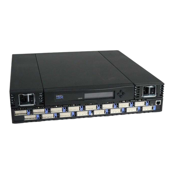
- Page 1 IBM SAN Fibre Channel Switch 2109 Model S16 Installation and Service Guide The IBM License Agreement for Machine Code is included in this book. Carefully read the agreement. By using this product you agree to abide by the terms of this agreement and applicable Copyright Laws.
- Page 3 IBM SAN Fibre Channel Switch 2109 Model S16 Installation and Service Guide SC26-7352-01...
- Page 4 FAX: 1-800-426-6209 You can also send your comments electronically to: starpubs@us.ibm.com When you send information to IBM, you grant IBM a nonexclusive right to use or distribute the information in any way it believes appropriate without incurring any obligation to you.
-
Page 5: Table Of Contents
System reported error ..... 33 Service reference table ..... . 35 © Copyright IBM Corp. 1999, 2000... - Page 6 Installing through Telnet..... 63 Installing through the IBM StorWatch Specialist ... . 63 Extended Fabrics .
- Page 7 Taiwan class A compliance statement ....134 IBM license agreement for Machine Code ....134...
- Page 8 ..... . 135 IBM warranty for Machines ....135 Warranty service .
-
Page 9: Figures
18. Power supply handle ......47 19. IBM GBIC module ......47 20. - Page 10 62. errShow command example ......118 viii IBM SAN Fibre Channel Switch: 2109 Model S16 Installation and Service Guide...
- Page 11 41. Diagnostic error messages ......122 42. System error messages ......125 © Copyright IBM Corp. 1999, 2000...
- Page 12 IBM SAN Fibre Channel Switch: 2109 Model S16 Installation and Service Guide...
-
Page 13: Safety And Environmental Notices
Translated safety notices The translation of the safety notices in this manual are contained in a separate manual. See the IBM External Devices Safety Information Manual , SA26-7003, for a translation of any danger and caution notices. Disposing of products This unit may contain batteries. - Page 14 IBM SAN Fibre Channel Switch: 2109 Model S16 Installation and Service Guide...
-
Page 15: About This Book
Failure to follow these instructions can cause damage to the machine. Limited vocabulary This book uses a specific range of words so that the text can be understood by IBM service support representatives in countries where English is not the primary language. -
Page 16: Related Publications
IBM 2109 Model S16 Switch. v IBM External Devices Safety Information , SA26-7003. This book provides translations of the Danger and Caution notices used in IBM 2109 switch publications. Related publications v Electrical Safety for IBM Customer Engineers , S229-8124... -
Page 17: Chapter 1. Introduction
Chapter 1. Introduction The IBM SAN Fibre Channel Switch 2109 Model S16 is a 16-port, fibre-channel, switch. The IBM 2109 Model S16 Switch consists of a system board with connectors for supporting up to 16 ports, and a fabric operating system for creating and managing a fabric. -
Page 18: Performance
F frames when the output port is free. Manageability The unit is managed using the 10BASE-T Ethernet port for Telnet or Web-based management using the IBM StorWatch Specialist. The switch also provides a front operator panel for simple switch configuration and diagnostics. System components The system board is enclosed in an air-cooled chassis that is either mounted in a standard rack or used as a stand-alone unit. -
Page 19: Power Supply
Figure 2. Short wavelength (SWL) laser fiber-optic GBIC module (P/N and labeling vary) Note: The SWL GBIC module uses a class 1 laser, which complies with the 21 CFR, subpart (J) as of the date of manufacture. LWL fiber-optic GBIC module The LWL fiber-optic GBIC module, with the SC connector color-coded blue, is based on long wavelength 1300-nm lasers supporting 1.0625-GBps link speeds. -
Page 20: Fibre-Channel Cable Connections
125 µm cladding diameter duplex cable Fiber cables connect to the front panel of the switch using standard dual SC plug connectors as shown in Figure 5 on page 5. IBM SAN Fibre Channel Switch: 2109 Model S16 Installation and Service Guide... -
Page 21: Front Panel
Figure 5. Dual SC fiber-optic plug connector The connectors are keyed and must be correctly aligned before they are inserted into the GBIC-module connector. In most cases, one of the two connector plugs is a different color to aid in proper connector alignment. Note: Remove the protective plug from the GBIC. -
Page 22: Front Panel Led Status Indicators
This could indicate that a loop back cable is installed, the fabric is IBM SAN Fibre Channel Switch: 2109 Model S16 Installation and Service Guide... -
Page 23: Diagnostics Overview
segmented (an E-port connection to another switch cannot be completed and the switches cannot form a fabric), or the 2109 Model S16 Switch has been connected to an incompatible switch. When frame traffic is being transferred on a port, the LED flickers fast green, showing that the port is active and is transferring data. -
Page 24: Loop (Fl) Connections
The system-board module is structured to accommodate a single channel FL_port interface module in the same slot used by the dual G_port interface module. Mixing of FL_port and G_port interface modules in different slots is permitted. IBM SAN Fibre Channel Switch: 2109 Model S16 Installation and Service Guide... -
Page 25: Chapter 2. Customer Planning
TestSANlet1_2109-1 System contacts (Contact name) System location B/003-3 Col C-4 Event trap level 0 - 5 Refer to the IBM SAN Fibre Channel Switch 2109 Model S16 User’s guide for additional information. Enable authentication traps RW community string dingo RO community string Trap recipients IP Address 192.20.236.3... - Page 26 The location where the firmware files are located. Firmware location The directory location on the StorWatch Server that has the firmware for the 2109. IBM recommends that a different directory be used for each level of firmware that is loaded. Switch name The name of this particular fibre channel switch.
-
Page 27: Blank Of A Planning Worksheet For A 2109 Switch
Users defined - access level SNMP information: System description System contacts System location Event trap level 0 - 5 See IBM SAN Fibre Channel Switch 2109 Model S16 User’s Guide Enable authentication traps RW community string RO community string Trap recipients IP address License keys Chapter 2. -
Page 28: Example Of A Configuration Worksheet For A 2109 Switch
| | | | | | | 2109-15 Port 13 2m (6 ft) | | | | | | | Open | | | | | | | K38 node 1 25m (82 ft) IBM SAN Fibre Channel Switch: 2109 Model S16 Installation and Service Guide... -
Page 29: Blank Of A Port Configuration Worksheet For A 2109 Switch
Table 9. Blank of a port configuration worksheet for a 2109 switch Port Device Device port Cable Port Notes Cable number name length type number | | | | | | | | | | | | | | | | | | | | | | | | | | | | | | | | | | | | | | | | | |... -
Page 30: Example Of A Zone Definitions Worksheet
| | | | Port (ID,P) 1, 10 Same EMC-1 dir 5 port 0 | | | | Port (ID,P) 15, 10 Same EMC–1 dir 5 port 0 IBM SAN Fibre Channel Switch: 2109 Model S16 Installation and Service Guide... -
Page 31: Blank Of A Zone Definitions Worksheet
Table 11. Blank of a zone definitions worksheet Zone member type Zone member Zone configuration Comments name (switch, port, WWN) | | | | Port (ID,P) | | | | Port (ID,P) | | | | Port (ID,P) | | | | Port (ID,P) | | | | Port (ID,P) -
Page 32: Zone Configuration Worksheet Example
| | | | Port (ID, P) 15, 11 Same EMC-1 dir 16 port 2 | | | | Port (ID, P) 15, 13 Same 2109-1 port 13 IBM SAN Fibre Channel Switch: 2109 Model S16 Installation and Service Guide... -
Page 33: Blank Of A Zone Configuration Worksheet
Table 13. Blank of a zone configuration worksheet Zone member type Zone Zone configuration Connects to member name (switch, port, WWN) | | | | Port (ID, P) | | | | Port (ID, P) | | | | Port (ID, P) | | | | Port (ID, P) | | | |... - Page 34 IBM SAN Fibre Channel Switch: 2109 Model S16 Installation and Service Guide...
-
Page 35: Chapter 3. Installing The Switch
Ensure that the disk or tape system Usually performed by a service installation has been completed. representative during target device installation. For tape attachment, ensure that the tape device driver was installed or updated. © Copyright IBM Corp. 1999, 2000... -
Page 36: Installing The Switch
None network hub where the switch will be installed. Note: The term server used here refers to the computer used for the IBM StorWatch Specialist. Installing the switch The 2109 Model S16 Switch is installed either in a rack-mount configuration or a tabletop configuration. - Page 37 Attention: Do not install this switch in a rack where the internal rack-ambient temperature will exceed 40°C. v Do not install this unit in a rack where the airflow is compromised. The airflow is from the back of the unit to the front; therefore, do not block the front or the back of the rack.
-
Page 38: Moving Slide
1. Open the rack-mounting brackets kit and mount the brackets to the wider fixed portion of the four slides. One bracket mounts to each end of the fixed portion of the slides as shown in Figure 9 on page 23. IBM SAN Fibre Channel Switch: 2109 Model S16 Installation and Service Guide... -
Page 39: Mounting The Fixed Portion Of The Rail And The Locking Ears To The Rack
Leave the mounting screws on the rear bracket finger tight. You will tighten these after the switch is installed. The brackets on the front should be tightened, leaving approximately 15 mm (5/8 in.) of the bracket in front of the end of the outer fixed slide member. -
Page 40: Installing The Optional Power Supply
It is the customer’s responsibility to ensure that the outlet is correctly wired and grounded to prevent an electrical shock. (72XXD201) IBM SAN Fibre Channel Switch: 2109 Model S16 Installation and Service Guide... -
Page 41: Installing Gbics
DANGER To prevent a possible electrical shock when installing the device, ensure that the power cord for that device is unplugged before installing signal cables. (72XXD204) If you do not have the optional second power supply, locate the power cord for the single power supply that is already installed in the machine frame. -
Page 42: Setting The Ip Address
Ethernet port. The locations of these ports are shown in Figure 14 on page 27. Set the IP address by using the pre-installation checklist you obtained from the customer LAN Administrator. IBM SAN Fibre Channel Switch: 2109 Model S16 Installation and Service Guide... -
Page 43: Setting The Ip Address Using The Ethernet Port
Power supply 2 Power supply 1 Operator panel Fiber Channel Switch 2109 S16 RJ-45 Ethernet connector SJ000054 Figure 14. Ethernet port connector Setting the IP address using the Ethernet port If you cannot use this method, go to “Setting the IP address from the front panel” on page 28. -
Page 44: Setting The Ip Address From The Front Panel
The Tab/Esc buttons tab through multiple options. When displaying a menu item, pressing the Tab/Esc button reverses through previous commands and, if pressed repeatedly, turns off the front panel display. IBM SAN Fibre Channel Switch: 2109 Model S16 Installation and Service Guide... - Page 45 Table 15. Control buttons (continued) Control Description button Enter The Enter button accepts the input and executes the selected function. When entering a number, the Up and Down buttons start in the slow mode and change to the fast mode if either button is held down. Most numbers go to a maximum of 255;...
- Page 46 If you press Yes, the switch displays: Updating config. This causes the new address to be stored. After the switch has made the change, it again displays: Domain. IBM SAN Fibre Channel Switch: 2109 Model S16 Installation and Service Guide...
-
Page 47: Switch Installation Verification
The latest code can be obtained from the SAN Fibre Channel Switch Web site at: www.ibm.com/storage/fcswitch This Web site provides instructions for downloading the code and loading it on the switch. -
Page 48: Downloading Firmware Using A Microsoft Windows Nt Operating System
PC (backward slash \) directory addressing. For example, from Windows NT the firmwareDownload command would be: firmwareDownload 192.111.2.1 , timm , /tmp/os/v2.0.1a_0621 . IBM SAN Fibre Channel Switch: 2109 Model S16 Installation and Service Guide... -
Page 49: Chapter 4. Maintenance Action Plans
For the latest information on the SAN Fibre Channel Switch, go to our Web site at: www.ibm.com/storage/fcswitch System reported error The customer has reported a switch-related system error message, or the customer has reported a failure when accessing storage or hosts that are attached to the © Copyright IBM Corp. 1999, 2000... - Page 50 Zoning is explained in the IBM SAN Fibre Channel Switch 2109 Model S16 Users Guide . To display and check zones, the customer must log on to the switch using Telnet in admin mode and issue the zoneShow command.
-
Page 51: Service Reference Table
Service reference table Table 16 shows a description of the error messages and the recommended actions. Table 16. Service reference table Error Description Action message Table 17. System reported error message Fan failure The customer has reported that a fan failure was reported to the system. - Page 52 4. After replacing the power supply, turn the power switch on and verify that the green power supply LED is on. If the green power supply LED is on, return the machine to the customer. IBM SAN Fibre Channel Switch: 2109 Model S16 Installation and Service Guide...
- Page 53 5. If the green power supply LED is not on, recheck the power cord seating, the power switch, and the wall outlet. If these are all correct, replace the chassis. See “Replacing the chassis with touchpad” on page 50. Replacing the chassis is a disruptive process.
- Page 54 10. If the previous steps did not resolve the problem, or if it is not possible to reattempt communications to verify correct switch function, continue with this procedure to ensure that the switch is good through the associated GBICs. IBM SAN Fibre Channel Switch: 2109 Model S16 Installation and Service Guide...
- Page 55 Abnormal port LED action (action 5) 1. If the port flashes slow yellow (flashes yellow every 2 seconds), the port is disabled. The customer needs to re-enable the port using the IBM StorWatch Specialist Web interface or by using a Telnet session. Instructions for disabling and re-enabling ports are in the IBM SAN Fibre-Channel Switch 2109 Model S16 Users Guide .
- Page 56 If the device cable is present, insert the cable into the GBIC. 7. If the port indicator shows no light, and a GBIC and cable are installed: IBM SAN Fibre Channel Switch: 2109 Model S16 Installation and Service Guide...
- Page 57 a. Ensure that the attached device is turned on and ready. b. If the attached device is turned on and ready, see “Some ports fail to communicate action (action 4)” on page 38. Abnormal ready LED action (action 6) You are here because you observed an abnormal ready LED (anything other than steady green).
- Page 58 OK. If not, the cable is bad. 3. If this is an IBM-provided cable, replace it. There are two lengths of cable available as FRUs for the switch [5 m (16.4 ft) and 25 m (82 ft) shortwave]. If these are appropriate, replace the cable.
- Page 59 7. If it is not possible or appropriate to access the switch in this fashion, replace the short cable. If it is an IBM-approved cable, ask the customer to replace it. If you are dealing with a long cable or one where both ends cannot be accessed at the switch, you need to have the cable installer test the cable.
- Page 60 IBM SAN Fibre Channel Switch: 2109 Model S16 Installation and Service Guide...
-
Page 61: Chapter 5. Replacing Frus
If possible, disconnect all power cords from the existing system before you add or remove a device. (72XXD203) DANGER Do not attempt to open the covers of the power supply. Power supplies are not serviceable and are replaced as a unit. (72XXD300) © Copyright IBM Corp. 1999, 2000... -
Page 62: Tools That Are Required
3. Pull out and lift up the handle from the top of the power supply unit. The handle is shown in Figure 18 on page 47. 4. Gently pull the unit out. IBM SAN Fibre Channel Switch: 2109 Model S16 Installation and Service Guide... -
Page 63: Installing A Power Supply
None. Removing a GBIC module Figure 19 shows an IBM GBIC. Pull down the swing handle on the front of the GBIC and pull it out. Carefully move the GBIC from side to side to unseat it. Figure 19. IBM GBIC module Installing a GBIC module Note: The GBIC module is keyed so it can be inserted only one way. -
Page 64: Replacing A Fan Assembly
These screws are accessible from the rear of the switch. Turn the screws counterclockwise until the assembly is forced out (spring loaded). 2. Carefully pull the assembly away from the chassis rear panel. Figure 20. Fan assembly IBM SAN Fibre Channel Switch: 2109 Model S16 Installation and Service Guide... -
Page 65: Installing A Fan Assembly
Installing a fan assembly Note: When reconnecting the power connector of the fan to its mating connector, be certain the connector is properly oriented before installing. Do not force the connector. 1. Slide the assembly into the back of the chassis. The power connector of the fan assembly should be in the down position. -
Page 66: Installing The System Board
Tools that are required The following tools are required: A number 2 Phillips head screwdriver. A number 4 flat head screwdriver. IBM SAN Fibre Channel Switch: 2109 Model S16 Installation and Service Guide... -
Page 67: Removing The Old Chassis
Removing the old chassis 1. Turn off the unit. 2. Remove the power supplies. See “Replacing the power supply” on page 45. 3. Remove the system board assembly. See “Replacing the system board assembly” on page 49. 4. Remove the fan assembly. See “Replacing a fan assembly” on page 48. Installing the new chassis 1. -
Page 68: Verifying A Repair That Did Not Require Turning The Switch Off
IP address, return the machine to the customer. 12. If you did not replace the system board, install the Ethernet cable and return the machine to the customer. IBM SAN Fibre Channel Switch: 2109 Model S16 Installation and Service Guide... -
Page 69: Chapter 6. Optional Features
2109 switch, are monitored. Fabric Watch runs on 2109 switches with Fabric OS, version 2.2 or later, and can be accessed through the IBM StorWatch Specialist, a Telnet interface, a Simple Management Network Protocol (SNMP)-based enterprise manager, or by modifying and uploading the Fabric Watch configuration file to the switch. -
Page 70: Threshold Behavior Models
Events can be selected for transitions between the boundaries. Rising or falling thresholds are typically used for rate-based counters. An error counter as a rising or falling threshold is illustrated in Figure 24 on page 55. IBM SAN Fibre Channel Switch: 2109 Model S16 Installation and Service Guide... -
Page 71: Installing Fabric Watch
The installation of Fabric Watch involves the installation of a license on each switch where you want to enable Fabric Watch. A license may have been installed in the switch at the factory. If not, contact your IBM sales representative to obtain a license key. -
Page 72: Installing Fabric Watch Through The Ibm Storwatch Specialist
The Fabric Watch feature is available as soon as step 5 is complete. Fabric Watch overview Fabric Watch provides the following information about each out-of-boundary condition discovered including: IBM SAN Fibre Channel Switch: 2109 Model S16 Installation and Service Guide... -
Page 73: Telnet Commands Overview
Enter. Note: Fabric Watch can be accessed simultaneously from different connections, by Telnet, SNMP, IBM StorWatch Specialist, or by modifying and uploading the Fabric Watch configuration file to the switch. If this happens, changes from one connection might not be updated to the other, and some may be lost. If Committing configuration... -
Page 74: Telnet Commands
Fabric Watch configuration file from a host. Operands None Example Example of reloading the Fabric Watch configuration: sw:admin> fwConfigReload fwConfigReload: Fabric Watch configuration reloaded See also configUpload configDownload fwClassInit fwConfigure fwShow IBM SAN Fibre Channel Switch: 2109 Model S16 Installation and Service Guide... - Page 75 fwConfigure command The fwConfigure command displays and allows modification of the Fabric Watch configuration and status. | | | Synopsis fwConfigure Availability Administrator Description Use to allow the admin account to display and modify threshold information and the Fabric Watch configuration. Switch elements monitored by Fabric Watch are divided into classes, which are further divided into areas.
- Page 76 2 : disable a threshold 3 : enable a threshold 4 : advanced configuration 5 : return to previous page Select choice => : (1..5) [5] See also fwClassInit fwConfigReload fwShow IBM SAN Fibre Channel Switch: 2109 Model S16 Installation and Service Guide...
- Page 77 fwShow command The fwShow command displays the thresholds monitored by Fabric Watch. | | | Synopsis fwShow Availability All users Description Use to display the thresholds monitored by Fabric Watch. If no parameters are entered, a summary of all thresholds is displayed and printed. If a valid threshold name is entered as a parameter, detailed information pertaining only to that threshold is displayed and printed.
-
Page 78: Remote Switch
2.2 or later installed. The switches must be configured the same. The installation of the remote switches involves the installation of a separate license on each of the two switches. Contact your IBM sales representative to obtain a license key. -
Page 79: Installing Through Telnet
1. Launch the Web browser, type the switch name or IP address in the Location/Address field, and press Enter. The IBM StorWatch Specialist launches, displaying the Fabric View. 2. Click the Admin button on the relevant switch panel. The logon window is displayed. -
Page 80: Extended Fabrics
A license may have been installed in the switch at the factory. If not, contact your IBM sales representative to obtain a license key. The 2109 Extended Fabrics 2.2 product requires a 2109 series switch with Fabric OS version 2.2 installed. -
Page 81: Installing Through The Ibm Storwatch Specialist
Using Extended Fabrics You can configure ports to support long distance links through Telnet or through the IBM StorWatch Specialist. For information about using the IBM StorWatch Specialist to configure ports, see the IBM StorWatch Specialist User’s Guide . This section provides the following information: v Configuring extended fabrics. -
Page 82: Accessing Through The Telnet Interface
10 km (6.2 miles). Level one long distance, up to 50 km (31 miles). A total of 27 full-size frame buffers are reserved for the port. IBM SAN Fibre Channel Switch: 2109 Model S16 Installation and Service Guide... - Page 83 3 Please enter the long distance level -- : (0..2) [0] 2 Committing configuration...done. For additional information, see the configure, portShow, and switchShow commands in the IBM SAN Fibre Channel Switch 2109 Model S16 User’s Guide. Chapter 6. Optional features...
- Page 84 IBM SAN Fibre Channel Switch: 2109 Model S16 Installation and Service Guide...
-
Page 85: Chapter 7. Management Tools
In order to manage a switch, you must have access to one of the available management methods. Telnet, SNMP, and IBM StorWatch Specialist require that the switch be accessible using a network connection. The network connection can be from the switch Ethernet port (out of band) or from fibre channel (in band). -
Page 86: Hardware Setup For Switch Management
To enable remote connection to the switch, the switch must have a valid IP address. Two IP addresses can be set; one for the external out-of-band Ethernet port and one for in-band fibre channel network access. IBM SAN Fibre Channel Switch: 2109 Model S16 Installation and Service Guide... -
Page 87: Setting Switch Ip Address Using The Front Panel
Setting switch IP address using the front panel See Figure 26 for the location and functions of each button on the front panel of the 2109 Model S16 Switch. Up button Display Enter button Tab/Esc button Fiber Channel Switch 2109 S16 RJ-45 10BASE-T connection Down button... -
Page 88: Front Panel Of The 2109 Model S16 Switch
9. Fibre-channel IP address [None]: press Enter. 10. Fibre-channel subnetmask [None]: press Enter. 11. Gateway address [current gateway address or None]: enter new gateway address or press Enter. IBM SAN Fibre Channel Switch: 2109 Model S16 Installation and Service Guide... -
Page 89: Setting The Ip Address
Note: This is the gateway address the customer provided or press Enter if none is required. 12. Ipaddress: admin> logout This ends the Telnet session. You have completed installation of the 2109 Model S16 Fibre Channel Switch. Setting the IP address As the admin user, enter: ipAddrSet This command prompts the user for the following:... -
Page 90: Changing Passwords
The information on an agent is known as the management information base (MIB). The MIB is an abstraction of configuration and status information. A specific type or class of management information is known as an MIB object or variable. For IBM SAN Fibre Channel Switch: 2109 Model S16 Installation and Service Guide... -
Page 91: Mib Tree
IBM 2109 sysObjectID(2) sysDescr(1) fcFabric(2) commDev(2) SJ000021 Figure 28. MIB tree An MIB object is uniquely identified or named by its position in the tree. A full object identifier consists of each branch along the path through the tree. For example, the object sysObjectID has the full identifier of 1.3.6.1.2.1.1.2. -
Page 92: Snmp Transports
Name server group v Event group v Fabric watch subsystem group (available with fabric watch license) For more information, see “Available MIB and trap files” on page 78. IBM SAN Fibre Channel Switch: 2109 Model S16 Installation and Service Guide... -
Page 93: Generic Traps
Generic traps Setting up the switch SNMP connection to an existing managed network allows the network system administrator to receive the following generic traps. coldStart indicates that the agent has reinitialized itself such that the agent configuration might be altered. This also indicates that the switch has restarted. -
Page 94: Managing Using The Management Server
Because the management server is accessed using its well-known address, an application can access management information with a minimal knowledge of the existing configuration. An application accesses one well-known place to obtain management information about the entire fabric. IBM SAN Fibre Channel Switch: 2109 Model S16 Installation and Service Guide... -
Page 95: Using The Management Server
The fabric topology view exposes the internal configuration of a fabric for management purposes. It contains interconnect information about switches and devices connected to the fabric. Under normal optional circumstances, a device (typically an FCP initiator) queries the name server for storage devices within its member zones. Because this limited view is not always sufficient, the management server provides the management application with a management view of the name server database. -
Page 96: Syslogd Support
The error identifier consisting of a module name, a dash and an error name. v The error severity. v Optional informational part. v Optional stack trace. IBM SAN Fibre Channel Switch: 2109 Model S16 Installation and Service Guide... -
Page 97: Message Classification
syslogd running on switch sw9 is sending log events to the UNIX machine called example. Figure 29 is an example of a No memory error generated by the shell. This is a severity 1 (LOG_CRITICAL) error. syslogd is configured to store the errors in the /var/adm/silkworm file. -
Page 98: Power-On Self-Test (Post)
When the switch is started, a series of commands are executed to test the switch. This procedure is called the POST. The fabric OS POST includes the following tests: ramTest - Bit write and read test of SDRAMS in the switch. IBM SAN Fibre Channel Switch: 2109 Model S16 Installation and Service Guide... - Page 99 portRegTest Bit write and read test of the ASIC SRAMs and registers. centralMemoryTest Bit write and read test of the ASIC central memory. cmiTest ASIC to ASIC connection test of the CMI bus. camTest Functional test of the CAM memory. portLoopbackTest Functional test of the switch by sending and receiving frames from the same port.
- Page 100 IBM SAN Fibre Channel Switch: 2109 Model S16 Installation and Service Guide...
-
Page 101: Chapter 8. Zoning Overview
Figure 33 on page 86 illustrates three zones with some overlap. It also contains devices that are not assigned to a zone, and are thus not active in the fabric if IBM zoning is enabled. © Copyright IBM Corp. 1999, 2000... - Page 102 Figure 33. A fabric with three zones IBM SAN Fibre Channel Switch: 2109 Model S16 Installation and Service Guide...
-
Page 103: Appendix A. Specifications
Table 24. Fabric management specifications Standard features Description Fabric management Simple name server, alias server, simple network management protocol (SNMP), Telnet, World Wide Web User interface RJ-45 front panel connector for 10BASE-T and 100BASE-T Ethernet © Copyright IBM Corp. 1999, 2000... -
Page 104: Optical Port Specifications
Height: 87.33 mm (3.44 in.), Width: 428.6 mm (16.88 in.), Depth: 450.0 mm (17.72 in.). Tabletop dimensions: Height: 87.33 mm (3.44 in.), Width: 428.6 mm (16.88 in.), Depth: 450.0 mm (17.72 in.). Weight: 28.5 lbs. IBM SAN Fibre Channel Switch: 2109 Model S16 Installation and Service Guide... -
Page 105: Power Supply Specifications
Power supply specifications The 2109 Model S16 Switch has a universal power supply capable of functioning worldwide without voltage jumpers or switches. The supply is autoranging in terms of accommodating input voltages and line frequencies. A semi-custom switching power supply, that is repackaged for the requirements of the switch enclosure architecture, is used. - Page 106 IBM SAN Fibre Channel Switch: 2109 Model S16 Installation and Service Guide...
-
Page 107: Appendix B. Diagnostics
Test Description Memory test Checks CPU RAM memory Port register test Checks the ASIC registers and SRAMs Central memory test Checks the system board SRAMs CMI conn test Checks the CMI bus between ASICs © Copyright IBM Corp. 1999, 2000... -
Page 108: Diagnostic Tests
See the “Diagnostic error messages” on page 122 for the actual error message descriptions and appropriate service actions. Running diagnostics from the front panel Figure 34 on page 93 shows the front panel buttons. IBM SAN Fibre Channel Switch: 2109 Model S16 Installation and Service Guide... -
Page 109: Front Panel Functionality
Up button Display Enter button Tab/Esc button Fiber Channel Switch 2109 S16 RJ-45 10BASE-T Down button connection SJ000062 Figure 34. Front panel functionality Control buttons Table 28 lists the primary control button functions. The function of the button changes depending on the menu level. Buttons either control the navigating through the menus or incrementing and decrementing numeric values. -
Page 110: Front Panel Switch Menus
The camTest command verifies that the SID translation required by QuickLoop and implemented using content addressable memories (CAM) is functioning correctly. The switch must be offline. IBM SAN Fibre Channel Switch: 2109 Model S16 Installation and Service Guide... -
Page 111: Centralmemorytest Example
Attention: This command cannot be executed on an operational switch. Before using the camTest command, disable the switch using the switchDisable command. Related error messages: DIAG-CAMINIT, DIAG-CAMSID, DIAG-XMIT centralmemorytest Table 30 shows the centralMemoryTest command which verifies that the central memory in each loom ASIC is functioning correctly by checking the following: v The built-in-self-repair (BISR) circuit in each loom chip does not report a failure to repair bad cells (bisr test). -
Page 112: Cmemretention Test Example
This command cannot be executed on an operational switch. Before issuing the cmiTest command, disable the switch using the switchDisable command. cmiTest example: The cmiTest command performs a ASIC to ASIC connection test of the CMI bus IBM SAN Fibre Channel Switch: 2109 Model S16 Installation and Service Guide... - Page 113 Table 32. cmiTest example Synopsis cmiTest [passCount] Availability Administrator Description Use this command to verify that the multiplexed 4-bit control message interface (CMI) point-to-point connection between two ASICs is functioning properly. Also use it to verify that a message with a bad checksum sets the error and interrupt status bits of the destination ASIC and that a message with a good checksum does not set an error or interrupt bit in any ASIC.
-
Page 114: Switch Setup To Run Crossporttest
System Memory Test at 0x1021d460 len 13091456 Figure 38. System memory test If the memory test is OK, the front panel activates the display shown in Figure 39 on page 99. IBM SAN Fibre Channel Switch: 2109 Model S16 Installation and Service Guide... -
Page 115: Ramtest
0x10199a10 len 13091456 ramTest: passed Figure 39. ramTest Related error messages: DIAG-MEMORY, DIAG-MEMSZ, DIAG-MEMNULL. portLoopbackTest The portLoopbackTest command verifies the intended functional operation of the switch by sending frames from the transmitter on each port back to the receiver on the same port using an internal hardware loopback. -
Page 116: Push Button Command Example
The switch must be offline. Related error messages: DIAG-REGERR, DIAG-REGERR_UNRST, DIAG-BUS_TIMEOUT. Switch offline Pressing Enter while Switch Offline is selected activates the display shown in Figure 44 on page 101. IBM SAN Fibre Channel Switch: 2109 Model S16 Installation and Service Guide... -
Page 117: Running Diagnostics Using Telnet
Switch Offline: Accept? Figure 44. Switch offline command example Tests that would jeopardize data transmission require taking the switch offline. If the switch is not offline, a prompt is displayed before the test is allowed to proceed. Note: Taking the switch offline disrupts switch operation. Switch online Pressing Enter while Switch online is selected activates the display shown in Figure 45. -
Page 118: Camtest Command Example
(chip number error test). Attention: This command cannot be performed on an operational switch. Before issuing the centralMemoryTest command, disable the switch, using the switchDisable command. IBM SAN Fibre Channel Switch: 2109 Model S16 Installation and Service Guide... -
Page 119: Centralmemorytest Command Example
switch: admin> centralMemoryTest Running Central Memory Test ... passed. Figure 47. centralMemoryTest command example Related error messages: DIAG-CMBISTRO, DIAG-CMBISRF, DIAG-LCMTO, DIAG-LCMRS, DIAG-LCMEM, DIAG-LCMEMTX, DIAG-CMNOBUF, DIAG-CMERRTYPE, DIAG-CMERRPTN, DIAG-PORTABSENT, DIAG-BADINIT, DIAG-TIMEOUT. cmemRetentionTest Figure 48 shows the cmemRetentionTest command, which is used to verify that data written into the SRAMs that make up the central memory are retained and that data bits do not drop when read after some amount of delay since the write operation. - Page 120 Note: Make sure that you reset GBIC mode before returning the machine to the customer. The GBIC mode is activated by executing the following command before executing the crossPortTest command: IBM SAN Fibre Channel Switch: 2109 Model S16 Installation and Service Guide...
- Page 121 sw:admin> setGbicMode 1 When activated, only ports with GBICs installed are included in the crossPortTest list of ports to test. For example, if only ports 0 and 3 have GBICs installed and the GBIC mode is activated, crossPortTest limits its testing solely to ports 0 and 3.
-
Page 122: Crossporttest Command Example
55 seconds (based on a 2109 Model S16) for warm or cold startups. A switch that is restarted without POST generates the DIAG-POST_SKIPPED error. Note: IBM recommends that POST processing always be run to ensure the operational status of the switch during the power-on stage. -
Page 123: Diagdisablepost Command Example
switch:admin> diagDisablePost Committing configuration ... done. On next reboot, POST will be skipped. Figure 52. diagDisablePost command example diagEnablePost Figure 53 shows the diagEnablePost command, which enables POST processing. The choice remains in effect across power-on and power-off cycles until toggled by the user. -
Page 124: Diagshow Command Example
(Tx) but may differ because of failure modes. portLoopbackTest Figure 55 on page 109 shows the portLoopbackTest command, which verifies the intended functional operation of the switch by sending frames from the transmitter IBM SAN Fibre Channel Switch: 2109 Model S16 Installation and Service Guide... -
Page 125: Portloopbacktest Command Example
on each port back to the receiver on the same port by way of an internal hardware loopback. It tests the switch circuitry up to the serial output of the ASIC. The loopback point chosen by the portLoopbackTest depends on what kind of GBIC module is present. -
Page 126: Portregtest Command Example
Figure 57 shows the ramTest command, which checks CPU RAM memory. This test validates proper memory function. switch: admin> ramTest Running System DRAM Test ..passed. Figure 57. ramTest command example Related error messages: DIAG-MEMORY, DIAG-MEMSZ, DIAG-MEMNULL. IBM SAN Fibre Channel Switch: 2109 Model S16 Installation and Service Guide... -
Page 127: Setgbicmode 1 Command Example
setGbicMode The GBIC mode, when enabled, forces the crossPortTest command or the spinSilk command to limit its testing to only those ports whose GBICs are detected as present. To enable GBIC mode, execute the command as shown in Figure 58. switch:admin>... - Page 128 Testing Loopback->13 port Testing Loopback->5 port Testing Loopback->12 port Testing Loopback->1 port Testing Loopback->10 port Testing Loopback->8 port Testing Loopback->6 port Testing Loopback->0 Transmitting ... done. Spinning ... IBM SAN Fibre Channel Switch: 2109 Model S16 Installation and Service Guide...
-
Page 129: Spinsilk Command Example 1
Table 36. spinSilk command example 1 (continued) Port Rx/Tx 1 of 2 million frames. Port Rx/Tx 1 of 2 million frames. Port Rx/Tx 1 of 2 million frames. Port Rx/Tx 1 of 2 million frames. Port Rx/Tx 1 of 2 million frames. -
Page 130: Sramretentiontest Command Example
IBM SAN Fibre Channel Switch: 2109 Model S16 Installation and Service Guide... -
Page 131: Supportshow Command Example
switch:admin> supportShow VxWorks: 5.3.1 Firmware: v2.2 Made on: Fri Mar 19 16:29:55 PST 1999 Flash: Fri Mar 19 16;30:19 pst 1999 BootProm: Tue Dec 29 17:32:38 PST 1998 none: No licenses 28 29 30 29 27 Centigrade 82 84 86 84 80 Fahrenheit Power Supply #1 is absent Power Supply #2 is OK Figure 61. - Page 132 IBM SAN Fibre Channel Switch: 2109 Model S16 Installation and Service Guide...
-
Page 133: Appendix C. Error Messages
Q to quit. Continue pressing Enter until the prompt (=>) is displayed. In Figure 62 on page 118, Error 02 represents a system error and Error 01 represents a diagnostic error (error number #004). Only diagnostic errors are assigned error numbers. © Copyright IBM Corp. 1999, 2000... -
Page 134: Diagnostic Error Message Formats
Replace the DRAM module or mainboard assembly portRegTest* Replace the mainboard assembly centralMemoryTest* Replace the mainboard assembly cmiTest* Replace the mainboard assembly cmemRetentionTest Replace the mainboard assembly sramRetentionTest Replace the mainboard assembly IBM SAN Fibre Channel Switch: 2109 Model S16 Installation and Service Guide... -
Page 135: Error Message Numbers
Table 38. Probable failure actions (continued) Failed test Action camTest* Replace the mainboard assembly portLoopbackTest* Replace the mainboard assembly crossPortTest Replace the mainboard assembly, GBIC or the fiber cable spinSilk Replace the mainboard assembly, GBIC or the fiber cable * These tests are run during the POST. For more information about these tests, refer to the individual command description in “Chapter 6. - Page 136 DIAG-ERRSTAT(BADORD) | | | 3047 DIAG-ERRSTAT(DISC3) | | | 304F DIAG-INIT | | | 305F DIAG-PORTDIED | | | 3060 DIAG-STATS (FTX) | | | 3061 DIAG-STATS (FRX) IBM SAN Fibre Channel Switch: 2109 Model S16 Installation and Service Guide...
-
Page 137: Repair Action Code Meanings For Diagnostic Error Messages
Table 39. Error message code defined (continued) Error Test name Error name number | | | 3062 DIAG-STATS (C3FRX) | | | 306E DIAG-DATA | | | 306F DIAG-TIMEOUT | | | 3070 DIAG-PORTABSENT | | | 3071 DIAG-XMIT | | | 3078 DIAG-PORTWRONG | | |... -
Page 138: Diagnostic Error Messages
ASIC or system board Err#2034 got CMI capture flag. failure DIAG-CMINOCAP cmiTest The CMI intended receiver ASIC ASIC or system board Err#2033 failed to get the CMI capture flag. failure IBM SAN Fibre Channel Switch: 2109 Model S16 Installation and Service Guide... - Page 139 Table 41. Diagnostic error messages (continued) | | | | | Message Failing test Description Probable cause Action DIAG-CMISA1 cmiTest An attempt to send a CMI ASIC failure Err#2032 message from ASIC to ASIC failed. | | | | DIAG-CMNOBUF centralMemoryTest The port could not get any buffer.
- Page 140 ASIC SRAM did not match Err#0415 the data previously written into the same location. | | | DIAG- portRegTest The port failed to unreset. ASIC failure REGERR_UNRST sramRetentionTest Err#0B16 Err#0416 IBM SAN Fibre Channel Switch: 2109 Model S16 Installation and Service Guide...
-
Page 141: System Error Messages
The fabric segmented. Incompatible fabric Reconfigure fabric or zones. For LOG_WARNING parameters/switches additional information, refer to the IBM SAN Fibre Channel Switch Conflict zones 2109 Model S16 User’s Guide. FABRIC, BADILS, Bad ISL-ELS size The ISL-ELS payload Contact customer support LOG_WARNING is wrong. - Page 142 Incompatible Hello timeout OS error Contact customer support LOG_ERROR from port OS error | | | HLO, INVHLO, Invalid Hello received from port OS error Contact customer support LOG_ERROR IBM SAN Fibre Channel Switch: 2109 Model S16 Installation and Service Guide...
- Page 143 Table 42. System error messages (continued) | | | | Message Description Probable Cause Action | | | LSDB, LSID, Link State ID’d out of range OS error Contact customer support LOG_ERROR LSDB, MAXINCARN, Local Link State Record OS error Contact customer support LOG_WARNING reached max incarnation...
- Page 144 Contact customer support LOG_CRITICAL | | | TEMP, 4_FAILED, Switch overheated Fan failure Contact customer support LOG_CRITICAL | | | TEMP, 5_FAILED, Switch overheated Fan failure Contact customer support LOG_CRITICAL IBM SAN Fibre Channel Switch: 2109 Model S16 Installation and Service Guide...
- Page 145 Table 42. System error messages (continued) | | | | Message Description Probable Cause Action | | | TIMERS, ENQFAIL, Invalid timeout value OS error Contact customer support LOG_CRITICAL | | | TIMERS, MSG, Invalid message OS error Contact customer support LOG_WARNING | | | UCAST, ADDPATH,...
- Page 146 IBM SAN Fibre Channel Switch: 2109 Model S16 Installation and Service Guide...
-
Page 147: Notices
Web sites. The materials at those Web sites are not part of the materials for this IBM product and use of those Web sites is at your own risk. IBM may use or distribute any of the information you supply in any way it believes appropriate without incurring any obligation to you. -
Page 148: Electronic Emission Statements
Properly shielded and grounded cables and connectors must be used in order to meet FCC emission limits. IBM is not responsible for any radio or television interference caused by using other than recommended cables and connectors or by unauthorized changes or modifications to this equipment. -
Page 149: Germany Compliance Statement
TV communications and to other electrical or electronic equipment. Such cables and connectors are available from IBM authorized dealers. IBM cannot accept responsibility for any interference caused by using other than recommended cables and connectors. -
Page 150: Japanese Voluntary Control Council For Interference (Vcci) Class 1 Statement
BIOS, Utilities, Diagnostics, Device Drivers, firmware, or Microcode (collectively called “Machine Code”), you accept the terms of this Agreement by your initial use of a Machine or Machine Code. The term “Machine” means an IBM Machine, its features, conversions, upgrades, elements or accessories, or any combination of them. -
Page 151: Statement Of Limited Warranty
2) conforms to IBM’s Official Published Specifications. The warranty period for a Machine is a specified, fixed period commencing on its Date of Installation. The date on your receipt is the Date of Installation, unless IBM or your reseller informs you otherwise. -
Page 152: Warranty Service
The replacement may not be new, but will be in good working order. If IBM or your reseller is unable to repair or replace the Machine, you may return it to your place of purchase and your money will be refunded. -
Page 153: Limitation Of Liability
Circumstances may arise where, because of a default on IBM’s part or other liability, you are entitled to recover damages from IBM. In each such instance, regardless of the basis on which you are entitled to claim damages from IBM (including fundamental breach, negligence, misrepresentation, or other contract or tort claim), IBM is liable only for: 1. - Page 154 IBM SAN Fibre Channel Switch: 2109 Model S16 Installation and Service Guide...
-
Page 155: Glossary
Glossary This glossary provides definitions for the fibre-channel and switch terminology used in the IBM 2109 Model S16 Installation and Service Guide . agent. The interface to a managed device alias server. A fabric software facility that supports multicast group management. - Page 156 E_port or an F_Port. A port is defined as a G_port when it is not yet connected or has not yet assumed a specific function in the fabric. IBM SAN Fibre Channel Switch: 2109 Model S16 Installation and Service Guide...
- Page 157 gateway. Hardware that connects incompatible networks by providing the necessary translation for both hardware and software. GBIC. Gigabit Interface Converter. A removable serial transceiver module designed to provide gigabaud capability for fibre channel (FC) and other products that use the same physical layer. Gbps.
- Page 158 A bit template that identifies to the TCP/IP protocol code the bits of the host address that are to be used for routing to specific subnets. SWL. Short wavelength tachyon. A type of host bus adapter. TCP. Transmission control protocol IBM SAN Fibre Channel Switch: 2109 Model S16 Installation and Service Guide...
- Page 159 toggle. To turn on and then off. trap (SNMP). A mechanism for SNMP agents to notify the SNMP management station of significant events. TTL. Time-to-live. tunneling. A technique for enabling two networks to communicate when the source and destination hosts are on the same type of network but there is a different network in between.
- Page 160 IBM SAN Fibre Channel Switch: 2109 Model S16 Installation and Service Guide...
-
Page 161: Index
88 assembly part number 45 ambient temperature 36 components 2 American National Standards Institute (ANSI) 87 installing 51 ANSI (American National Standards Institute) 87, 139 removing 51 anti-static bag 50 types 87 © Copyright IBM Corp. 1999, 2000... -
Page 162: Control Buttons
66 components, system 2 degraders 64 configuration mode bit 66 agent 78 distortion, harmonic 89 defined 139 DNS (domain name server) 140 effective 140 domain 30 IBM SAN Fibre Channel Switch: 2109 Model S16 Installation and Service Guide... -
Page 163: Gbic
(ESD) 140 installing 55 electrostatic discharge (ESD) wrist grounding strap 49 through Telnet 55 ELP (extended link parameters) 104, 140 through the IBM StorWatch Specialist 56 Enterprise specific traps 77 introducing 53 environmental notices, safety xi license 53, 55... - Page 164 (HBA) 141 replacing 45 hot fix version 34 FSPF (fibre-channel shortest path first) 140 humidity fwClassInit command 57, 58 nonoperating 88 fwConfigReload command 57, 58 operating 88 IBM SAN Fibre Channel Switch: 2109 Model S16 Installation and Service Guide...
- Page 165 137 remote switch license 63 library, publications xiii remote switch license through Telnet 63 license remote switch license through the IBM StorWatch add extended fabric license to switch 65 Specialist 63 agreement for machine code, IBM 134 switch 19, 20...
- Page 166 24 managing with Telnet ordering publications xiii changing passwords 74 default user name 73 OS (operating system) 142 manufactured parts, new and used 135 OS service pack 19 IBM SAN Fibre Channel Switch: 2109 Model S16 Installation and Service Guide...
- Page 167 62 requirements 21 installing 62 specifications 89 installing through Telnet 63 power-on self-test (POST) 82, 142 installing through the IBM StorWatch Specialist 63 power-on self-test, verifying 7 introducing the 62 power supply required operating system version 62 description of 3...
-
Page 168: Chassis With Touchpad 50
135 (780 - 850 nm.) 88 Taiwan class A compliance 134 optical link 87 static IP address 20 SWL 142 SIMMS (single in-line modules) 142 status, port 6 IBM SAN Fibre Channel Switch: 2109 Model S16 Installation and Service Guide... - Page 169 92, 94, 101 universal 2 camTest 8, 102 warranty central memory 92, 101 extent 136 centralmemory 95 IBM 135 centralMemoryTest 8, 95, 102 service 136 chip number error 95 statement 135 CMem data retention 92 switchDisable 8 CMEM data retention 101...
- Page 170 WWW (world-wide web) 143 UNIX host, downloading firmware from 31 UNIX trademarks 132 upgrade procedure, switch 31 users of this book xiii using zone extended fabrics 65 alias 143 IBM SAN Fibre Channel Switch: 2109 Model S16 Installation and Service Guide...
- Page 171 zone (continued) configuration 143 configuration worksheet 17 configuration worksheet example 16 definitions worksheet 15 zoning Administering security 85 determining 34 introduction to 85 non-member devices 85 optimizing IT resources 85 overview 85 Index...
- Page 172 IBM SAN Fibre Channel Switch: 2109 Model S16 Installation and Service Guide...
- Page 173 Thank you for your responses. May we contact you? h Yes h No When you send comments to IBM, you grant IBM a nonexclusive right to use or distribute your comments in any way it believes appropriate without incurring any obligation to you. Name...
- Page 174 Readers’ Comments — We’d Like to Hear from You Cut or Fold Along Line SC26-7352-01 Fold and Tape Please do not staple Fold and Tape _ _ _ _ _ _ _ _ _ _ _ _ _ _ _ _ _ _ _ _ _ _ _ _ _ _ _ _ _ _ _ _ _ _ _ _ _ _ _ _ _ _ _ _ _ _ _ _ _ _ _ _ _ _ _ _ _ _ _ _ _ _ _ _ _ _ _ _ _ _ _ _ _ _ _ _ _ _ _ _ _ _ _ _ _ _ _ _ _ NO POSTAGE NECESSARY IF MAILED IN THE...
- Page 175 Thank you for your responses. May we contact you? h Yes h No When you send comments to IBM, you grant IBM a nonexclusive right to use or distribute your comments in any way it believes appropriate without incurring any obligation to you. Name...
- Page 176 Readers’ Comments — We’d Like to Hear from You Cut or Fold Along Line SC26-7352-01 Fold and Tape Please do not staple Fold and Tape _ _ _ _ _ _ _ _ _ _ _ _ _ _ _ _ _ _ _ _ _ _ _ _ _ _ _ _ _ _ _ _ _ _ _ _ _ _ _ _ _ _ _ _ _ _ _ _ _ _ _ _ _ _ _ _ _ _ _ _ _ _ _ _ _ _ _ _ _ _ _ _ _ _ _ _ _ _ _ _ _ _ _ _ _ _ _ _ _ NO POSTAGE NECESSARY IF MAILED IN THE...
- Page 178 Part Number: 19P1958 Printed in the United States of America on recycled paper containing 10% recovered post-consumer fiber. SC26-7352-01...
Need help?
Do you have a question about the 2109 - SAN Fibre Channel Switch Model S16 and is the answer not in the manual?
Questions and answers