HME Wireless 6000 Installation Instructions Manual
Wireless drive-thru audio system
Hide thumbs
Also See for Wireless 6000:
- Operating instructions manual (27 pages) ,
- Operating instructions manual (19 pages)

Related Manuals for HME Wireless 6000


Summary of Contents for HME Wireless 6000
- Page 1 HME# 400518 Rev - 8/29/03 Wireless 6000 Wireless Drive-Thru Audio System Installation Instructions...
-
Page 2: Table Of Contents
Cable Pulling ....................12 2.3.3 Outside Speaker and Microphone Installation and Cable Connections ..13 2.3.4 Optional External Vehicle Detector Installation..........16 2.3.5 Optional HME Vehicle Detector Board (VDB) Installation ......16 2.3.6 External Message Repeater Installation ............17 2.3.7 Internal Message Repeater Setup ..............18 2.3.8 Early Warning Setup ..................18... - Page 3 SP2500LP cable connections .................. 15 External message repeater connections ..............17 Wiring diagram, Wireless 6000, Half-Duplex with VDB but no Switcher Board ..25 Wiring diagram, Wireless 6000, Half-Duplex with VDB and Switcher Board ..26 Wiring diagram, Wireless 6000, Full-Duplex with VDB but no Switcher Board ..27 Wiring diagram, Wireless 6000, Full-Duplex with VDB and Switcher Board ...
-
Page 4: System Description
The Wireless 6000 is a wireless audio system primarily for use at quick-service restaurants. An optional vehicle detector board can also be used with the system. As you unpack the Wireless 6000, check the packing list for each item to verify receipt of all components and equipment listed. -
Page 5: Base Station
Nine level controls are used to set VAA level, Vehicle tone level, audio source levels at the grill speaker, outbound audio source levels at the outside speaker and the inbound level from the speaker post microphone. Figure 2. Wireless 6000 Base Station... -
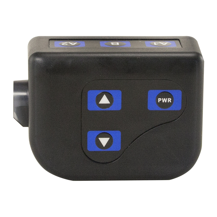
Page 6: Communicator Controls
® 1.2.2 COM6000BP COMMUNICATOR Channel “A1” button Channel “B” button Channel “A2” button Power button Volume-up button Volume-down button Headset cable connector socket Figure 3. Communicator controls 1. Features and Controls 2. How to Wear the Beltpac & Headset • Wear the headset with the microphone on your right or left side next to your mouth. - Page 7 ® 3. How to Use the COM6000BP COMMUNICATOR Controls The Communicator control buttons have a snap action. They will activate when pressed firmly. Use your fingertips, not your fingernails, to press the buttons. a. Power On/Off • Power On – Press and release the PWR (power) button. A voice message in the earpiece will say “power on,”...
-
Page 8: Communicator
4. COMMUNICATOR Registration Prior to operation of the Wireless 6000 system, each Communicator must be registered for use with a specific base station. The base station will then recognize all registered Communicators when their power is on, differentiating between them and interfering transmissions from other electronic equipment operating on similar frequencies. -
Page 9: Communicator ® Battery-Release Latch
5. Battery Removal and Replacement Battery-release latch ® Figure 6. COMMUNICATOR battery-release latch TO CHANGE BATTERIES: When a battery is becoming weak, a voice in the earpiece will say “Change battery.” When this happens, take the Communicator out of its pouch and remove its battery by carefully sliding the battery-release latch in the direction of the arrow shown in Figure 6. -
Page 10: Battery Charger
1.2.3 Battery Charger IMPORTANT: Before installing the system, connect the AC adapter to the battery ® charger and plug it into an AC electrical outlet. Place all the COMMUNICATOR batteries into it for charging while the system is being installed. 1. -
Page 11: Optional Equipment
3. Battery Charging • Insert battery in one of four charging ports until it clicks in place. • Battery charging time is approximately 2 hours. • Yellow light next to each battery port stays on while port is empty. When battery is in port, yellow light flashing next to battery port indicates CHARGE PENDING, which means the temperature where the charger is located is out of the battery’s operating range (32 -104... -
Page 12: System Installation And Setup
If there is a 2400MHz cordless telephone nearby, interference may occur. However, because the Wireless 6000 is a frequency-hopping system, this problem is unlikely. If it does occur, changing frequencies on the telephone may alleviate the problem. If not, move the phone as... -
Page 13: Electrical Interference
AC electrical outlet and place all COMMUNICATOR batteries into it for charging while the other equipment is being installed. Approximately 3 hours is required for installation of the Wireless 6000. Before installing the system, coordinate the time of installation with the store owner/manager to minimize disruption of business. -
Page 14: Installation Procedure
INSTALLATION PROCEDURE 2.3.1 Base Station Installation Discuss the location of the base station with the store owner or manager. It should be mounted with the bottom of the cabinet no more than 5 feet (1.52 meters) above the floor, away from grease and large metal objects. It must be near enough to an available AC electrical outlet to reach the outlet with the 10 foot (3 meter) AC power adapter cord. -
Page 15: Cable Pulling
Never run high-voltage cables in the same conduit with audio or loop cables. The recommended HME cable contains four color-coded, insulated wires and a bare shield (drain) wire. This cable can be used to connect any Wireless 6000 component to the base station. -
Page 16: Outside Speaker And Microphone Installation And Cable Connections
2.3.3 Outside Speaker and Microphone Installation and Cable Connections This section describes standard, full-duplex installations, using the standard microphone and the SP2500LP Low-Profile Speaker. Specific installation requirements may vary. Refer to the wiring diagrams on pages 25 — 28 for cable connections. Although the standard microphone and SP2500LP will provide optimum performance, in some cases the DM1 Microphone may be used. -
Page 17: Microphone Unit And Foam Inserts Shown In Typical Speaker Post Installation
• Open the speaker post and remove any existing equipment, foam or debris. If there is an existing microphone, remove it and disconnect the microphone cable from it. • Splice the wires of the microphone cable (new or existing) from the audio system to the wires of the cable extending from the microphone unit, according to the audio system... -
Page 18: Mark Speaker Post Or Menu Board Through Wire Hole In Rear Panel Of Sp2500Lp Speaker Assembly
Keep in mind that the SP2500LP must be mounted at least 2 feet (610 mm) from the microphone, center-to-center. • Hold the rear panel of the SP2500LP flat against the surface of the speaker post or menu board, at the desired mounting location, as shown in Figure 16. -
Page 19: Optional External Vehicle Detector Installation
2.3.5 Optional HME Vehicle Detector Board (VDB) Installation To install an HME VDB in the base station, follow the instructions below. • Open the base station by pushing the latches on the front cover and VERY CAREFULLY guiding the cover downward. -
Page 20: External Message Repeater Installation
2.3.6 External Message Repeater Installation If an external message repeater is used, it must be wired in series with the outside speaker. It also requires a vehicle-present signal. Connect the message repeater vehicle-present input to the isolated vehicle detector output on the Audio Circuit Board. NOTE: No output detect will be generated if the base station power is removed. -
Page 21: Internal Message Repeater Setup
Refer to page 22 for “Red Message Control” and “Green Message Control” switch functions and message recording instructions. If a System 30 Timer is installed with the Wireless 6000, the timer alert output can be used to trigger tones in the headset or a message to be played by the message repeater. -
Page 22: System Functional Check And Operation
NOISE REDUCTION ADJUSTMENT When the ClearSound feature of the Wireless 6000 is turned on, it provides four levels of noise reduction. It can be adjusted for the best balance of noise reduction and voice quality possible, considering the store’s environment. -
Page 23: Operation
The COM6000BP can be operated in Hands-Free (HF), Auto-Hands-Free (AHF) or Push-To-Talk (PTT) modes. If your store does not have HF capability, the Wireless 6000 should be operated according to section III. A. 3. below in single-lane stores, or section III. B. 3. (page 9) in dual-lane stores. -
Page 24: Dual-Lane Operation
3.3.2 Dual-Lane Operation (two base stations operating two speaker posts) 1. Hands-Free (HF) Mode: ! With the power off, press and hold the volume-up and B buttons while pressing and releasing the PWR button to turn the power on in the HF mode. The Communicator will remember this setting. ! As a customer enters a drive-thru lane, you will hear an alert tone (single beep for Lane 1, double beep for Lane 2) in your headset, and you will be able to hear the customer at the speaker post or menu board if that lane is selected. -
Page 25: Message Repeater Operation
3.3.4 Message Repeater Operation ACTION RESULT Press and release the RECORD MODE The RED MESSAGE RECORD light button on the base station once. on the base station will come on. The MESSAGE RECORD light on the Press and hold button B on the To record ®... -
Page 26: In Case Of Problems
Battery may be low or defective. Check Power light. If not lit, replace battery. Headset may be defective. Use another headset. Call HME. * Communicator Communicator power may not be Press Power ON/OFF button on channel A or B is not Communicator. - Page 27 If not, move the phone as far as practical from the base station, or ask the customer to use another type phone. Call HME Customer Support at 1-800-848-4468 if assistance is required.
-
Page 28: Wiring Diagram, Wireless 6000, Half-Duplex With Vdb But No Switcher Board
VEH DETECT IN 1 2 3 4 1 2 3 4 1 2 3 4 5 6 7 8 1 2 3 4 5 6 7 8 Wiring Diagram Wireless 6000, Half -Duplex Figure 20. with VDB but no Switcher Board... -
Page 29: Wiring Diagram, Wireless 6000, Half-Duplex With Vdb And Switcher Board
VEH DETECT IN 1 2 3 4 5 6 7 8 1 2 3 4 5 6 7 8 1 2 3 4 1 2 3 4 Wiring Diagram Wireless 6000, Half -Duplex Figure 21. with VDB and Switcher Board... -
Page 30: Wiring Diagram, Wireless 6000, Full-Duplex With Vdb But No Switcher Board
VEH DETECT IN 1 2 3 4 1 2 3 4 1 2 3 4 5 6 7 8 1 2 3 4 5 6 7 8 Wiring Diagram Wireless 6000, Full -Duplex Figure 22. with VDB but no Switcher Board... -
Page 31: Wiring Diagram, Wireless 6000, Full-Duplex With Vdb And Switcher Board
VEH DETECT IN 1 2 3 4 1 2 3 4 1 2 3 4 5 6 7 8 1 2 3 4 5 6 7 8 Wiring Diagram Wireless 6000, Full -Duplex Figure 23. with VDB and Switcher Board... -
Page 32: Wireless 6000 Base Station Circuit Board Adjustments
1 2 3 4 5 6 7 8 1 2 3 4 1 2 3 4 R292 - Transmit message level R320 - Line in level R9 - Transmit audio level Wireless 6000 Figure 24. Base Station Circuit Board Adjustments (one side only) -
Page 33: Wireless 6000 Transceiver Board Adjustments, Connectors And Indicators
3 = Auto HF 4 = Not used Status light Communicator ID display Clear All Reset button Registration button Shield Start Registration button Ant 2 Ant 1 Antenna connectors Wireless 6000 Transceiver Board Figure 25. Adjustments, Connectors and Indicators (one side only) -
Page 34: Wireless 6000 Base Station Circuit Board Jumpers
(AVC) ON/OFF Automatic Volume Control Inbound Outbound audio audio OFF = Factory Default OFF = ClearSound bypassed ON = Factory default Line Out Select Outbound Grill Spkr Outbound = Factory Default Wireless 6000 Figure 26. Base Station Circuit Board Jumpers... -
Page 35: Wireless 6000 Base Station Circuit Board Dip Switch Functions
ON – Vehicle present tone allowed to play when vehicle arrives OFF – Vehicle present tone NOT allowed to play when vehicle arrives Level 1 Level 2 Level 3 Level 4 12dB Wireless 6000 Figure 27. Base Station Circuit Board DIP Switch Functions... -
Page 36: Appendix A: Base 6000 Interface Description
APPENDIX A: BASE 6000 INTERFACE DESCRIPTION Audio Circuit Board J26,5 Car 2 J2 — Speaker In/Out J26,6 Ground J2,1 Ground J26,7 TX Audio 2 J2,2 /A Talk J26,8 Ground J2,3 Relay 1 Common J26,9 RX Audio A2 J2,4 Relay 1 Normally Open J26,10 RX Audio B2 or B1 + B2 J2,5 Relay 1 Normally Closed... - Page 37 J1,18 TX/RX audio ground JP5 — Line Output Select J1,19 TX audio 1 JP5,1 Outbound J1,20 Not used JP5,2 Common JP5,3 Ceiling Speaker JP2 — ClearSound Bypass Jumper JP2,1 Audio channel 2 input J29 — AC Power JP2,2 Outbound Audio J29,1 16VAC power input JP2,3...
- Page 38 Switcher Circuit Board J1 — DM1 Interconnect J4 — Backup System Interconnect J1,1 Microphone in J4,1 Loop J1,2 Microphone in J4,2 Loop J1,3 Ground J4,3 Negative vehicle detection signal J1,4 +12VDC J4,4 Ground J1,5 Not used J4,5 Positive vehicle detection signal J4,6 Not used J2 —...
-
Page 39: Appendix B: Functional Description Of Block Diagram
APPENDIX B: FUNCTIONAL DESCRIPTION OF BLOCK DIAGRAM The base station is the main control and interface of the Wireless 6000. All audio to and from the ® speaker post and COMMUNICATOR routes through the base station. The base station contains the following circuit boards: audio board, transceiver board, optional switcher board and optional vehicle detector board. -
Page 40: Appendix C: Wireless 6000 Specifications
APPENDIX C: WIRELESS 6000 SPECIFICATIONS Base Station 1. Voltage input 16VAC ±2.5V 2. AC current input 2.5A maximum 3. Audio distortion 5% maximum level 4. Outside speaker output 3 watts RMS into 8 ohms 5. Ceiling speaker power 3 watts RMS into 8 ohms 6. -
Page 41: Appendix D: Sp2000A Speaker/Microphone Installation
APPENDIX D: SP2000A SPEAKER/MICROPHONE INSTALLATION Installation Drill four c inch (3.2 mm) pilot holes at the spots shown on Figure D-1 A, in the flange of the SP2000A. Hold the enclosed SP2000A mounting template against the outside of the speaker grill on the speaker post or menu board, at the desired location. -
Page 42: Appendix E: Dm1 Microphone Installation
APPENDIX E: DM1 MICROPHONE INSTALLATION The following instructions are for installation of the DM1 Microphone in standard, full-duplex installations, both inside and outside a speaker post or menu board. Specific installation requirements may vary. Refer to wiring diagrams on pages A-15 and A-16 for cable connections. -
Page 43: Dm1 And Foam Inserts Shown In Typical Spp2 Speaker Post Installation
• Remove the rubber plug from the back of the DM1 microphone unit, and locate the POT inside the hole. Turn the POT approximately ¾ of the way clockwise, then replace the rubber plug. • Place the enclosed thin piece of foam against the inside of the metal grill. -
Page 44: Installing Gasket And Bracket
Figure E-3. Installing gasket and bracket Figure E-4. Routing cable through strain relief • Position the DM1 Microphone unit between the sides of the bracket and align the two holes in the unit with the two slots on the bracket. Fasten the unit in place with two of the four remaining lock washers and screws, inserting the screws into the holes... -
Page 45: Install Windscreen On Microphone
• Insert the front end of the microphone into the foam-lined hole in the windscreen so the screw holes on the windscreen flanges are aligned with the holes on the sides of the microphone mounting bracket as shown in Figure E-6. •... -
Page 46: Attach Mounting Bracket
To install the DM1 Microphone on the outside of a menu board, use the menu-board mounting bracket to mount the DM1 as follows. • Disconnect the microphone cable from the existing SP2000A Microphone Unit or SP2000D Speaker/Microphone in the menu board. •... - Page 47 1 2 3 4 5 6 7 8 1 2 3 4 5 6 7 8 1 2 3 4 1 2 3 4 Wiring Diagram Wireless 6000, Full -Duplex with VDB and Switcher Board Figure E-10. and DM1 Microphone...
- Page 48 1 2 3 4 1 2 3 4 1 2 3 4 5 6 7 8 1 2 3 4 5 6 7 8 Wiring Diagram Wireless 6000, Full -Duplex with VDB, Switcher Board, Figure E-11. DM1 Microphone and IC300...
- Page 49 1 2 3 4 1 2 3 4 1 2 3 4 5 6 7 8 1 2 3 4 5 6 7 8 Wiring Diagram Wireless 6000, Full -Duplex with VDB, Switcher Board, Figure E-12. DM3 Microphone and IC300...
-
Page 50: Fcc Notice
FCC NOTICE This device complies with Part 15 of the FCC rules. Operation is subject to the following two conditions: (1) This device may not cause harmful interference, and (2) This device must accept any interference received, including interference that may cause undesired operation. NOTE: This equipment has been tested and found to comply with the limits for a Class A digital device, pursuant to Part 15 of the FCC rules.
Need help?
Do you have a question about the Wireless 6000 and is the answer not in the manual?
Questions and answers