HME Wireless 6000 Operating Instructions Manual
Wireless drive-thru audio system
Hide thumbs
Also See for Wireless 6000:
- Operating instructions manual (27 pages) ,
- Installation instructions manual (50 pages)

Related Manuals for HME Wireless 6000


Summary of Contents for HME Wireless 6000
- Page 1 HME# 400519 Rev A 9/8/03 Wireless 6000 Wireless Drive-Thru Audio System Operating Instructions...
-
Page 2: Table Of Contents
OPTIONAL EQUIPMENT ....................17 VIII. FCC NOTICE........................17 List of Figures Figure Title Page Wireless 6000 equipment......................1 Wireless 6000 Base Station with front door open..............2 ® COM6000BP COMMUNICATOR beltpac ................4 Wearing the Communicator headset ..................4 ® COMMUNICATOR battery-release latch ................5 Registration buttons and indicators ..................6 Batteries in charger .........................7... -
Page 3: General
GENERAL The Wireless 6000 is a wireless audio system primarily for use at quick-service restaurants. EQUIPMENT FUNCTIONS AND USE Figure 1. Wireless 6000 equipment... -
Page 4: Base Station
A. Base Station The base station is the electronic heart of the Wireless 6000. It contains the circuitry through which all functions of the drive-thru audio system are channeled. External base station features are shown in Figure 2, and described on page 3. Its internal controls and connectors are shown in Figure 8 on page 14. - Page 5 Base Station External Features Front — (See A on Figure 2.) • Four power supply lights are on when the base station has AC power. • “A” TALK light is on during channel-A transmission. • “B” TALK light is on during channel-B transmission. •...
-
Page 6: Com6000Bp Communicator
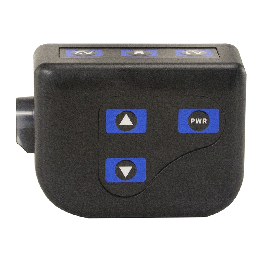
® B. COM6000BP COMMUNICATOR 1. Features and Controls Channel “A1” button Channel “B” button Channel “A2” button Power button Volume-up button Volume-down button Headset cable connector socket ® Figure 3. COM6000BP COMMUNICATOR beltpac 2. How to Wear the Communicator • Wear the headset with the microphone on your right or left side next to your mouth. •... -
Page 7: Battery-Release Latch
® 3. How to Use the COM6000BP COMMUNICATOR Controls The Communicator control buttons have a snap action. They will activate when pressed firmly. Use your fingertips, not your fingernails, to press the buttons. a. Power On/Off • Power On – Press and release the PWR (power) button. A voice message in the earpiece will say “power on,”... -
Page 8: Registration Buttons And Indicators
® 5. COMMUNICATOR Registration During installation of the Wireless 6000 system, each Communicator was registered for use with a specific base station. The base station thereby recognizes all registered Communicators when their power is on, differentiating between them and interfering transmissions from other electronic equipment operating on similar frequencies. -
Page 9: Battery Charger
C. Battery Charger Up to four batteries can be charged in the charger at the same time. Charging time is approximately 2.5 hours. The battery status lights next to each charging port are explained below. Up to six fully charged batteries can be stored in the battery storage ports. •... -
Page 10: Wireless 6000 Operation
The COM6000BP can be operated in Hands-Free (HF), Auto-Hands-Free (AHF) or Push-To-Talk (PTT) modes. If your store does not have HF capability, the Wireless 6000 should be operated according to section III. A. 3. below in single-lane stores, or section III. B. 3. (page 9) in dual-lane stores. -
Page 11: Dual-Lane Operation
B. Dual-Lane Operation (two base stations for two speaker posts) 1. Hands-Free (HF) Mode: ! With the power off, press and hold the volume-up and B buttons while pressing and releasing the PWR button to turn the power on in the HF mode. The Communicator will remember this setting. ! As a customer enters a drive-thru lane, you will hear an alert tone (single beep for Lane 1, double beep for Lane 2) in your headset, and you will be able to hear the customer at the speaker post or menu board if that lane is selected. -
Page 12: Internal Communication
Board, it will not be possible to use a wired backup system. If there is a Switcher Board, place the S2 switch in the IN position to use the wired backup system. When using the Wireless 6000 system, the S2 switch must be in the OUT position. -
Page 13: Message Repeater Operation
F. Message Repeater Operation ACTION RESULT Press and release the RECORD MODE The red MESSAGE RECORD light button on the base station once. on the base station will come on. Press and hold button B on the The MESSAGE RECORD light on the To record ®... -
Page 14: Equipment Care And Cleaning
• Foam muffs on headset earpieces can easily be replaced for sanitary purposes. To order extra foam muffs, call your local HME sales representative. 2. Battery Charger Avoid splashing water or grease on the battery charger. -
Page 15: In Case Of Problems
ANT1 and ANT2 near lower-left corner of transceiver circuit board. Pull and remove each connector plug, and check to be certain pin inside it is not bent. If not, call HME. Circuit board may be defective. Call HME. *... - Page 16 HME equipment after the electricity comes on again, unplug the AC power adapters from their electrical outlets and wait 15 seconds, then plug them back in.
-
Page 17: Figure 9
9 10 11 12 13 14 15 HEARTBEAT Figure 9. Base Station Internal Controls and Indicators ® COMMUNICATOR ID display Status light Reset button Ant2 antenna connector Ant1 antenna connector Start registration button Clear all registration button Indicator lights RECORD (See Figure 2) VEHICLE PRESENT “B”... -
Page 18: Specifications
SPECIFICATIONS Base Station Voltage input 16VAC ±2.5V AC current input 2.5A maximum Audio distortion 5% maximum level Outside speaker output 3 watts RMS into 8 ohms Ceiling speaker power 3 watts RMS into 8 ohms Switches/Controls 2-position vehicle detector switch (Normal — Override/Reset) (front panel only) 2-position “Speed Team”... -
Page 19: Optional Equipment
VII. OPTIONAL EQUIPMENT Equipment Model Number ® COMMUNICATOR COM6000BP Battery for Communicator BAT40 Headset Earmuff No model number Ceiling Speaker MM100 Ultrasonic Vehicle Detector Vehicle Detector Board VDB101 Vehicle Detector Loop (underground) VDL100 Message Repeater MR300 Low-Profile Speaker SP2500LP Microphone Mode Switch (dual lane) MS1000 Switcher Circuit Board...
Need help?
Do you have a question about the Wireless 6000 and is the answer not in the manual?
Questions and answers