Omega DP41-B User Manual
Universal input meter
Hide thumbs
Also See for DP41-B:
- User manual (94 pages) ,
- Operation manual (2 pages) ,
- Operation manual (2 pages)
Table of Contents
Advertisement
Quick Links
Download this manual
See also:
Operating Manual
Advertisement
Table of Contents
Troubleshooting

Related Manuals for Omega DP41-B


Summary of Contents for Omega DP41-B
- Page 1 RoHS 2 Compliant User’ s Guide Shop on line at ® omega.com ® e-mail: info@omega.com For Latest Product Manuals omegamanual.info DP41-B Universal Input Meter...
- Page 2 The information contained in this document is believed to be correct but OMEGA Engineering, Inc. accepts no liability for any errors it contains, and reserves the right to alter specifications without notice.
-
Page 3: Table Of Contents
Table of Contents SECTION 1 INTRODUCTION Description........................1 Features........................1 Available Options and Accessories ................2 Modes of Operation ......................3 SECTION 2 UNPACKING ........................4 SECTION 3 SAFETY CONSIDERATIONS ..................6 SECTION 4 PARTS OF THE METER Front of the Meter ......................7 Rear of the Meter......................10 SECTION 5 SETUP Conditions Requiring Dissassembly ................12... - Page 4 Table of Contents SECTION 7 SIGNAL AND POWER INPUT CONNECTIONS Introduction ........................29 Signal Input Connections -Process ................29 Signal Input Connections - Temperature ..............31 Signal Input Connections - Strain ................33 Cold Junction Compensation Board Installation for Thermocouples ......36 7.5.1 Cold Junction Compensation Board Wiring ..........37 7.5.2 Thermocouple Wire Color ................37 Connecting Main AC Power..................38...
- Page 5 Table of Contents SECTION 17 MULTI-POINT SCALE AND OFFSET MENU CONFIGURATION FLOWCHART ..65 SECTION 18 MULTI-POINT SCALE AND OFFSET MENU CONFIGURATION: (MP.SC.OF) ..66 SECTION 19 OUTPUT CONFIGURATION MENU FLOWCHART..........70 SECTION 20 OUTPUT CONFIGURATION MENU: (OUt.CNF) 20.1 ANA.OUt Enter Output Configuration Menu ............71 20.2 Ot.SC.OF Enter output Scale and Offset Configuration Submenu......73 SECTION 21 SETPOINT CONFIGURATION MENU FLOWCHART ..........74...
- Page 6 Table of Contents SECTION 31 EXTERNAL CONTROL LINES 31.1 TARE (PIN 1) ......................101 31.2 PEAK (PIN 2)......................101 31.3 VALLEY (PIN 3) ......................102 31.4 SWLIN2 (PIN 4) ......................102 31.5 EXTERNAL RESET (PIN 5) ..................102 31.6 NO CONNECTION (PIN 6) ..................102 31.7 DIGITAL RETURN (PIN 7)..................102 31.8 +5 V (PIN 8)......................102...
- Page 7 Figures Figure 4-1 Front Detail........................7 Figure 4-2 Connector Label (AC Powered and DC Powered Detail)..........10 Figure 4-3 Rear View ........................11 Figure 5-1 Meter Exploded View ....................13 Figure 5-2 Board Assembly Removing/Installing Detail..............14 Figure 5-3 Optional Board Locations ....................16 Figure 5-4 Signal Input Board ......................17 Figure 5-5 Main Board ........................18...
- Page 8 Tables Table 4-1 Rear Connector Descriptions ..................11 Table 5-1 Main Board Jumper Selection Table................18 Table 5-2 RS-232 / RS-485 Jumper Selection Table ..............19 Table 5-3 4 Relay Board Jumper Selection Table ................20 Table 6-1 Sensor Excitation Main Board Jumper Selection Table ..........28 Table 7-1 Thermocouple Wire Colors....................37 Table 16-1...
- Page 9 Notes, Warnings, and Cautions Information that is especially important to note is identified by these labels: • NOTE • WARNING • CAUTION • IMPORTANT NOTE: provides you with information that is important to successfully setup and use the Programmable Digital Meter. CAUTION or WARNING: tells you about the risk of electric shock.
- Page 10 Notes viii...
-
Page 11: Introduction
Introduction 1.1 Description This versatile ultra high-performance meter handles a broad spectrum of dc voltage and current ranges, nine thermocouple types, multiple RTD's, and signals from strain gauge transducers such as load cells and pressure transducers, as well as potentiometric inputs. It also features ten point linearization of input signals, progammable by the user for custom applications. -
Page 12: Available Options And Accessories
Introduction 1.3 Available Options and Accessories The following options are available. Optional boards are either installed at the time of purchase, or available as separate items and installed by the user after purchase. -T/C Thermocouple Temperature Compensation Connector Kit Four Form-C SPDT Relay Output Board Isolated 14 bit Analog Output Board -C24 Serial Communications RS-232* + RS-485** + MODBUS... -
Page 13: Modes Of Operation
Introduction 1.4 Modes of Operation • This unit has two different modes of operation. The first, Run Mode, is used to display values for the process variable, and to display or clear peak and valley values. The other mode, Menu Configuration Mode, is used to navigate through the menu options and configure the controller. -
Page 14: Unpacking
Unpacking Unpack all items and make sure that every item on the packing list is present. The items you should receive are listed below. If something is missing, use the phone number, listed in this manual, for the Customer Service Department nearest you. Also, inspect the shipping container and enclosed equipment for any signs of damage. - Page 15 Unpacking Rear Protective Cover with Screw 20-Socket Ribbon Connector (P2 Connector) part 7 Panel-Mounting Gaskets (1 Spare) part #8 Operator’s Manual part 9 Other items may also be in the box depending on the options ordered. Refer to specific options as described previously.
-
Page 16: Safety Considerations
Safety Considerations 3.1 SAFETY CONSIDERATIONS This device is marked with the international caution symbol. It is important to read this manual before installing or commissioning this device as it contains important information relating to Safety and EMC (Electromagnetic Compatibility). Unpacking & Inspection Unpack the instrument and inspect for obvious shipping damage. -
Page 17: Parts Of The Meter
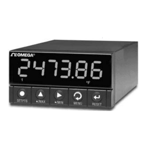
Parts of the Meter 4.1 FRONT OF THE METER The following is a brief description of each part of the front of the meter. ˚C ˚F ˚K SETPTS / MIN MENU RESET / MAX Figure 4-1. Front Detail ITEM DESCRIPTION 6-digit, 9 segment, alphanumeric 0.68”... - Page 18 Parts of the Meter BUTTON Function in Configuration Mode • This button functions only in Run Mode. When the Setpoint/Alarm features are unlocked, pressing this button sequentially recalls the previous setpoint settings SETPTS to the display. After the ‘ /MIN’ and ‘ /MAX’ buttons are used to alter those values, as desired, pressing the ‘SETPTS’...
- Page 19 Parts of the Meter BUTTON Function in Configuration Mode • To enter the Menu, the user must first press ‘MENU’ button. • To select “older -style” of Menu Configuration, "MENU 2", press ‘MENU’ button while Display is showing Firmware Version Number and only after applying the power.
-
Page 20: Rear Of The Meter
Parts of the Meter 4.2 REAR OF THE METER The following is a brief description of each part of the rear of the meter. The labeling on the top of the mounting sleeve (not the case) identifies the location of the connectors found at the rear of the meter. Figure 4-2 shows this labeling. -
Page 21: Figure 4-3 Rear View
Parts of the Meter Figure 4-3 shows the rear of the meter with the optional 4-relay output board, ethernet board and analog output board installed. P18A P18B ETHERNET RESET Figure 4-3. Rear View CONNECTOR # DESCRIPTION AC Power Connector or DC Power Connector External I/O Connector Input Connector Optional RS-232/RS-485 or Ethernet Connector... -
Page 22: Setup
Setup 5.1 CONDITIONS REQUIRING DISASSEMBLY You may need to remove the sleeve or open the unit for several reasons: To inspect the rating label on the case (Section 5.2.1). To install optional output board(s) (Section 5.2.2). To mount the unit in a panel (Section 5.2.4). 5.2 ASSEMBLY/DISASSEMBLY OPENING THE UNIT Your unit is fully assembled, but not wired. -
Page 23: Figure 5-1 Meter Exploded View
Setup COVER PROTECTIVE COVER MOUNTING THUMBNUTS SCREW GASKET SIGNAL INPUT BOARD SLEEVE POWER BOARD MAIN BOARD ASSY CASE BEZEL Figure 5-1. Meter Exploded View Using Figures 5-1 as a guide, follow these simple instructions to open the unit: IMPORTANT: Turn-off the power and input signals from the unit before proceeding. Failure to do so may result in injury! Remove the cover mounting screw that secures the rear protective cover to the unit, and remove the Rear Protective Cover. -
Page 24: Figure 5-2 Board Assembly Removing/Installing Detail
Setup SIGNAL INPUT JUMPER LABEL MICRO-PROCESSOR VERSION # MAIN BOARD ASSY BEND DETENTS OUTWARD TO INSTALL/REMOVE MAIN BOARD CASE ETHERNET (OPTIONAL) VERSION # PRODUCT IDENTIFICATION LABEL Figure 5-2. Board Assembly Removing/Installing Detail The meter is now disassembled to the point where you can check and configure jumpers and install option boards. -
Page 25: Safety Precaution/Product Id Label
Setup 5.2.1 SAFETY PRECAUTION/PRODUCT ID LABEL To look at the Rating/Product ID label on the case, you must follow the first step as described in Section 5-2. Refer to Figure 5-2 for the location of the Product Identification label. The meter is protected in accordance with Class I of EN61010. Refer to Safety Considerations page. WARNING: If your meter is to be wired to sensors to control inputs that could be hazardous potentials, these potentials will be carried to the 20-pin output connector (P2) at the rear. -
Page 26: Optional Board(S) Installation
Setup 5.2.2 OPTIONAL BOARD(S) INSTALLATION To install optional printed circuit board(s): “Reveal the Main Board” (refer to Section 5.2, Disassembly). Using Figure 5-3 as a reference, insert option board(s) into the corresponding connector(s) on the main board. Each circuit board is keyed to fit in it’s own position. 4 RELAY OUTPUT BD ANALOG OUTPUT BD RS232/RS485 BD... -
Page 27: How To Access Jumpers
Setup 5.2.3 HOW TO ACCESS JUMPERS To gain access to jumper S1 and S2 used to configure input type remove the mounting sleeve. The jumpers may be accessed through the slot in the case. To gain access to jumpers on the main board, for excitation and lockout selection: “Reveal the main board”... -
Page 28: Figure 5-5 Main Board
Setup POTENTIOMETER DISPLAY BOARD SIGNAL INPUT BOARD SOLDER-SWITCH MAIN "A" & "B"LOCATED BOARD ON UNDERSIDE POWER OF BOARD BOARD "A" "A" "B" "B" DC POWERED UNIT AC POWERED UNIT S3A and S3C used for MENU2 only. Figure 5-5. Main Board S3A (installed, default) MENU Pushbutton: used for programming S3A (not installed) -
Page 29: Figure 5-7 Rs-232/Rs-485 Option Board
Setup Refer to your Serial Communications Option Manual for more details. Figure 5-10. Analog Output Option Board Figure 5-7. RS-232/RS-485 Option Board JUMPER RS232 RS485 HALF DUPLEX RS485 FULL DUPLEX S1-A CLOSE OPEN OPEN S1-B OPEN CLOSE OPEN S2-A OPEN CLOSE CLOSE S3-A... -
Page 30: Figure 5-8 4-Relay Output Option Board
Setup P18B P18A Refer to your Relay Output Option Manual for more details. Figure 5-8. 4 Relay Output Option Board The table below shows which jumpers are assigned to each relay. Defaults have asterisks. re 4 Relay Output Board Wiring Connections Table 5-3 4 Relay Board Jumper Selction FUNCTION... -
Page 31: Panel-Mount Assembly
Setup S1-A must be closed. Refer to your Analog Output Option Manual for more details. Figure 5-9. Analog Output Option Board 5.2.4 PANEL-MOUNT ASSEMBLY The meter can be mounted in a panel so that the front of the meter is flush with the vertical panel surface. -
Page 32: Figure 5-10 Panel Mounting Assembly
Setup PANEL THICKNESS 0.25 [6.4] MAX 0.03 [0.8] MIN REAR PROTECTIVE COVER 0.06 COVER [1.5] 1.772 +0.024/-.000 MOUNTING 4PLCS [45.00 +0.61/-0.00] SCREW THUMBNUTS 3.622 +0.032/-.000 [92.00 +0.81/-0.00] PANEL SLEEVE METER CASE GASKET BEZEL Figure 5-10. Panel Mounting Assembly Punch or cut a hole in the panel using the panel cutout dimensions in Figure 5-10. Remove burrs and paint the panel as required. - Page 33 Setup WARNING: Do not “turn-on” the ac power and input signals until all connections are connected to the meter. Set P1, the AC power connector, aside and connect or reconnect all other connectors to the back of the meter using Figure 4-3 in Section 4.2 as guides. Connect P1 last.
-
Page 34: Figure 6-1 S1 And S2 Jumper Locations On Signal Input Board
Jumper Settings This section is for the configuration and setup of your jumper positions for readrate, unipolar or bipolar signal input, sensor input signal jumpers, sensor excitation jumpers, pushbutton lockouts and lockout of lockout configuration menus. Figure 6-1. S1 and S2 Jumper Locations on Signal Input Board... -
Page 35: Jumper Positions
Jumper Positions 6.1 THERMOCOUPLE Input: S1_G/J; S2_A/B/K, jumpers are closed as shown: 6.2 RTD Input: 6.2.1 For RTDs: S1_H; S2_A/B/F/J, jumpers are closed as shown: 6.2.2 For RTD 10 ohm copper: S1_H; S2_A/B/F/J/L, jumpers are closed as shown: 6.3 VOLTAGE/PROCESS VALUE Input: 6.3.1 For ±... -
Page 36: For ± 50V, 0-100V Ranges
Jumper Positions 6.3.4 For ± 50V, 0-100V ranges: S1_K/A/B; SD2_G/H, jumpers are closed as shown: 6.4 CURRENT/PROCESS VALUE Input: 6.4.1 For 0-20mA or 4-20mA range: S1_K; S2_A/B/C/D, jumpers are closed as shown: 6.5 BRIDGE Input: 6.5.1 For ± 50mV, 0-100mV ranges with Internal Excitation: S1_L;... -
Page 37: For ±5 V, 0-10 V Ranges Wtih Internal Excitation
Jumper Positions 6.5.5 For ± 5V, 0-10V ranges with Internal Excitation: S1_L/C/D; S2_G/H, jumpers are closed as shown: 6.5.6 For ± 5V, 0-10V ranges with External Excitation: S1_L/C/D; S2_H, jumpers are closed as shown: 6.5.7 For ± 50V, 0-100V ranges with Internal Excitation: S1_L/A/B;... -
Page 38: Potentiometer Input
Jumper Positions 6.5.11 POTENTIOMETER Input: S1_K/G/C/D; S2_C/G/H jumpers are closed as shown: Jumper Function S4A (installed) + solder jumper B Selects 10 Vdc Sensor Excitation (default) S4A (not installed) + solder jumper A Selects 24 Vdc Sensor Excitation Table 6-1. Sensor Excitation Main Board Jumper Selection Refer to Figure 5-5 for solder jumper locations. -
Page 39: Signal And Power Input Connections
Signal and Power Input Connections 7.1 INTRODUCTION The following describes how to connect your sensors to your meter with and without sensor ex ci ta tion and how to connect the AC power to your meter. Prior to wiring the sensor to the meter, check with a multimeter that a proper excitation exists. -
Page 40: Figure 7-3 Voltage Input Without Sensor Excitation
Signal and Power Input Connections +OUTPUT VOLTAGE – S OUTPUT METER Figure 7-3. Voltage Input Without Sensor Excitation +EXCITATION +OUTPUT Jumper VOLTAGE – S S2-C COMMON Closed METER – E JUMPER USER PROVIDED Figure 7-4. 3-Wire Voltage Input With Sensor Excitation +EXCITATION +OUTPUT Jumper... -
Page 41: Signal Input Connections - Temperature
Signal and Power Input Connections – S METER JUMPER USER PROVIDED Figure 7-6. Potentiometer Connections with Internal Power Supply and Ratio Measurement. – S METER – E JUMPER USER PROVIDED Figure 7-7. Potentiometer Connections with External Power Supply and Ratio Measurement (Remove Jumper S2-G) 7.3 SIGNAL INPUT CONNECTIONS - TEMPERATURE The following Figures (7-8 through 7-11) show the connections for Thermocouple and RTD Inputs. -
Page 42: Figure 7-9 Potentiometer Connections With 2-Wire Rtd
Signal and Power Input Connections – S METER – E – R Figure 7-9. RTD Connections with 2-wire RTD – S METER – E – R Figure 7-10. RTD Connections with 3-wire RTD – S METER – E – R Figure 7-11. -
Page 43: Signal Input Connections - Strain
Signal and Power Input Connections 7.4 SIGNAL INPUT CONNECTIONS - STRAIN The following Figures (7-12 through 7-19) show the connections for voltage, current and po ten ti om e ter inputs: (4-20mA) – S METER Figure 7-12. Current Input Without Sensor Excitation (4-20mA) –... -
Page 44: Figure 7-15 3-Wire Voltage Input With Sensor Excitation
Signal and Power Input Connections +EXCITATION +OUTPUT Jumper VOLTAGE – S S2-C COMMON Closed METER – E JUMPER USER PROVIDED Figure 7-15. 3-Wire Voltage Input With Sensor Excitation +EXCITATION +OUTPUT VOLTAGE – S OUTPUT METER EXCITATION – E Figure 7-16. 4-Wire Voltage/Bridge Input With Sensor Excitation +50 mV –... -
Page 45: Figure 7-18 Potentiometer Connections With Internal Power Supply And Ratio Measurement
Signal and Power Input Connections – S METER – E JUMPER USER PROVIDED Figure 7-18. Potentiometer Connections with Internal Power Supply and Ratio Measurement – S METER – E JUMPER USER PROVIDED Figure 7-19. Potentiometer Connections with External Power Supply and Ratio Measurement (Remove jumper S2-G) -
Page 46: Cold Junction Compensation Board Installation For Thermocouples
Signal and Power Input Connections 7.5 COLD JUNCTION COMPENSATION BOARD INSTALLATION FOR THERMOCOUPLES To setup the rear protective cover with the P3 and P9 connectors (and Cold-Junction Compensation Board), proceed with the following (Refer to Figure 7-20). 1) Obtain P3 and P9 connectors and the thermocouple rear protective cover. 2) Put the two (2) connectors P3 and P9 into the corresponding male connectors at the rear of the meter. -
Page 47: Cold Junction Compensation Board Wiring
Signal and Power Input Connections 7.5.1 COLD JUNCTION COMPENSATION BOARD WIRING Figure 7-21 shows the wiring hookup for thermocouples. Use the following table to determine which colored wired get connected to the positive and negative terminals. Note: Positive (+) and Negative (-) wiring designations are molded into the plastic cover. –... -
Page 48: Connecting Main Ac Power
Signal and Power Input Connections FRANCE GERMANY WIRE COLORS WIRE COLORS _ LEAD _ LEAD TYPE + LEAD + LEAD Yellow Black Blue Yellow Purple Green Yellow Blue Brown Yellow Purple Black No Standard-See USA No Standard-See USA Yellow Green White Yellow Green... -
Page 49: Connecting Main Dc Power
Signal and Power Input Connections Earth ground MUST be connected to the same earth ground used by the signal source, in order to achieve published stability and accuracy specifications. AC Power Equivalent DC Power 90 to 240 Vac~ 115 to 340 Vdc= NEUTRAL EARTH LINE... -
Page 50: Setpoint Settings Menu Flowchart
Setpoint Settings Menu Flowchart 8 SETPOINT SETTINGS MENU FLOWCHART push :Run mode SETPTS button :Setpoint 1 00000.0 :Setpoint 1 Value :Setpoint 2 00000.0 :Setpoint 2 Value :Setpoint 3 00000.0 :Setpoint 3 Value :Setpoint 4 00000.0 :Setoint 4 Value :Run mode Once this ‘SETPTS’... -
Page 51: Setpoint Settings Menu
Setpoint Settings Menu 9 ACTIVE BUTTONS: ‘SETPTS’, ‘ /MAX’, ‘ /MIN’. Press ‘SETPTS’ 1) The display shows "SP1" momentarily then "00000.0" or previous setpoint value with first digit flashing. If any digit or value is not flashing that setpoint value‘s modification, the ‘MAX’ and ‘MIN’ buttons are disabled or locked. -
Page 52: Section 10 Main Menu Configuration Flowchart
Main Menu Configuration Flowchart 10 MAIN MENU CONFIGURATION FLOWCHART push :Run mode MENU button INPUt :INPUT selection Menu RdG.CNF :READING CONFIGURATION Menu INP.CNF :INPUT CONFIGURATION Menu :MULTI-POINT SCALE & OFFSET CONFIGURATION Menu MP.SC.OF :OUTPUT CONFIGURATION Menu OUt.CNF :SETPOINT CONFIGURATION Menu SP.CNF AL.CNF :ALARM CONFIGURATION Menu... -
Page 53: Section 11 Input Type Menu Flowchart: (Input)
Input Type Menu Flowchart 11 INPUT TYPE MENU FLOWCHART: (INPUt) -
Page 54: Section 12 Input Type Selection
Input Type Selection 12 INPUT TYPE SELECTION: (INPUt) 12.1 INPUT TYPE: (THERMOCOUPLE) INPUt ENTER INPUT TYPE MENU: Press ‘MENU’ 1) Display shows "INPUt" Input Menu. Press ‘RESET/ENTER’ 2) Display flashes "VOLt" or previous stored input type. Press ‘ /MAX’ 3) Scroll through the available following input type selection list. Display flashes: "VOLt"... -
Page 55: Input Type: (Rtd)
Input Type Selection 12.2 INPUT TYPE: ( RTD ) ENTER INPUT TYPE MENU: Press ‘MENU’ 1) Display shows "INPUt" Input Menu. Press ‘RESET/ENTER’ 2) Display flashes "VOLt" (default) or previous stored input type. Press ‘ /MAX’ 3) Scroll through the available following input type selection list. Display flashes: "VOLt"... -
Page 56: Input Type: (Dc Voltage/Process Value)
Input Type Selection 12.3 INPUT TYPE: (DC VOLTAGE/PROCESS VALUE) ENTER INPUT TYPE MENU: Press ‘MENU’ 1) Display shows "INPUt" Input Menu. Press ‘RESET/ENTER’ 2) Display flashes "VOLt" (default) or previous stored input type. Press ‘ /MAX’ 3) Scroll through the available following input type selection list. Display flashes: "VOLt"... -
Page 57: Input Type: (Dc Current)
Input Type Selection 12.4 INPUT TYPE: (DC CURRENT) ENTER INPUT TYPE MENU: Press ‘MENU’ 1) Display shows "INPUt" Input Menu. Press ‘RESET/ENTER’ 2) Display flashes "VOLt" (default) or previous stored input type. Press ‘ /MAX’ 3) Scroll through the available following input type selection list. Display flashes: "VOLt"... -
Page 58: Input Type: (Bridge)
Input Type Selection 12.5 INPUT TYPE: (BRIDGE) ENTER INPUT TYPE MENU: Press ‘MENU’ 1) Display shows "INPUt" Input Menu. Press ‘RESET/ENTER’ 2) Display flashes "VOLt" (default) or previous stored input type. Press ‘ /MAX’ 3) Scroll through the available following input type selection list. Display flashes: "VOLt"... -
Page 59: Input Type: (Potentiometer)
Input Type Selection 12.6 INPUT TYPE: (POTENTIOMETER) ENTER INPUT TYPE MENU: Press ‘MENU’ 1) Display shows "INPUt" Input Menu. Press ‘RESET/ENTER’ 2) Display flashes "VOLt" (default) or previous stored input type. Press ‘ /MAX’ 3) Scroll through the available following input type selection list. Display: "VOLt"... -
Page 60: Section 13 Reading Configuration Menu And Flowchart
Reading Configuration Menu Flowchart 13 READING CONFIGURATION MENU and FLOWCHART: (RdG.CNF) RdG.CNF RdG SC (value) dIRECt ENAbLE RdG OF (value) Rd.SC.OF 2.C d INt (Reading Scale & Offset) (2 coordinate formula) dISAbL Offset=0 ON.LINE MANUAL Scale=1 INPUt 1 INPUt 1 UNt.tMP (Input 1 value) (Input 1 value) -
Page 61: Rd.sc.of Enter Reading Scale And Offset Submenu
Reading Configuration Menu 14 READING CONFIGURATION MENU: RdG.CNF ENTER READING CONFIGURATION MENU: Press ‘MENU’ 1) Twice though Main Menu items and display shows "RdG.CNF ". Press ‘RESET/ENTER’ 2) Display shows "Rd.SC.OF " Reading Scale & Offset menu. Press ‘MENU’ 3) Scroll through the following sequence of available Reading Configuration Menu selection list: "Rd.SC.OF"... - Page 62 Reading Configuration Menu Press ‘RESET/ENTER’ 4) To enter Reading Scale & Offset configuration Submenu if display shows "Rd.SC.OF" (First Item of "RdG.CNF" Menu). Press ‘RESET/ENTER’ 5) Display shows and flashes "dISAbL" disable (as default, Reading Scale=1.0 and Reading Offset=0.0). Press ‘ /MAX’ 6) Display flashes either "ENAbLE"...
- Page 63 Reading Configuration Menu 2.Cd In READING SCALE & OFFSET 2-COORDINATE FORMAT MENU: Input voltage or current can be converted or scaled into values appropriate for the process or signal being measured. A reading may be displayed, for example, in units of weight or velocity instead of in amperes and volts.
- Page 64 Reading Configuration Menu Press ‘RESET/ENTER’ 22) Display shows "xxxxxx" some 6-digit number, represents the value of "INPUt 1" as taken from live input source measurement for desired value. Press ‘RESET/ENTER’ 23) Display shows "REAd 1" Item #2 of coordinate #1. Press ‘RESET/ENTER’...
-
Page 65: Unt.tmp Enter Temperature Unit Selection Submenu
Reading Configuration Menu 14.2 UNt.tMP Enter TEMPERATURE UNIT SELECTION SUBMENU: 1) To enter TEMPERATURE UNIT SELECTION Submenu if display shows "UNt.tMP" (Second Item of "RdG.CNF" Menu). Press ‘RESET/ENTER’ 2) Display shows flashing "C" (default) and front display shows °C accordingly at the bottom right side or previous temperature Unit selection. -
Page 66: Filter Enter Filter Configuration Submenu
Reading Configuration Menu 14.4 FILtER Enter FILTER CONFIGURATION SUBMENU: Press ‘RESET/ENTER’ 12) Display shows "CNt by" Counter by or round-off feature. To enter, Press ‘RESET/ENTER’). Press ‘MENU’ 13) Scroll through 3 available selections of Filter configuration: "CNt by", "FILt.tP" and "FILt.tM". Refer to the flowchart below. CNt by Enter COUNT BY FILTER FUNCTION MENU: Press ‘RESET/ENTER’... -
Page 67: Fls.dsp Enter Flashing Display Control Submenu
Reading Configuration Menu 14.5 FLS.dSP Enter FLASHING DISPLAY CONTROL SUBMENU: ENAbLE SP1.FLS FLS.dSP (Setpoint Flashing) (Flashing Display) dISAbL ENAbLE SP2.FLS dISAbL ENAbLE AL1.FLS (Alarm 1 Flashing) dISAbL ENAbLE AL2.FLS dISAbL Press ‘RESET/ENTER’ 23) Display shows "SP1.FLS" Setpoint 1 Flashing. Press ‘RESET/ENTER’ 24) Display flashes "dISAbL"... -
Page 68: Section 15 Input Configuration Flowchart
Input Configuration Menu Flowchart 15 INPUT CONFIGURATION FLOWCHART INP.CNF LIN.FRE (Input Configuration ) (Line Frequency & Hz) Ad.RAtE (Analog to Digital Rate) MOdE ENAbLE C.JUN.OF dISAbL tC.CO.JC Accessible IF your INPUT selection: (Thermocouple Cold Junction) dISAbL ENAbLE CAL 0 (Field Calib.) NORMAL Accessible IF bRdG.LM... -
Page 69: Section 16 Input Configuration Menu: (Inp.cnf)
Input Configuration Menu 16 INPUT CONFIGURATION MENU: (INP.CNF) INP.CNF ENTER INPUT CONFIGURATION MENU: INP.CNF (Input Configuration) L IN.FRE Ad.RAtE IN.SC.OF MOdE (Line Frequency in Hz) (Analog to Digital Rate) (Input Scale & Offset) Press ‘MENU’ 1) Three times though Main Menu items and display shows "INP.CNF". Press ‘RESET/ENTER’... -
Page 70: Ad.rate Enter Analog To Digital Rate Submenu
Input Configuration Menu 16.2 Ad.RAtE Enter ANALOG TO DIGITAL RATE SUBMENU: Press ‘RESET/ENTER’ 7) Display flashes "0" or previous selection. Press ‘ /MAX’ 8) Scroll through the 6 available selections as 0, 1, 2, 3, 4, and 5 for your choice of selection. Refer to below Table for your specific application conversion speed. -
Page 71: Field Calibration For Cold Junction Compensation
Input Configuration Menu In case of "tC" input type: Press ‘RESET/ENTER’ 10) Display shows "tC.CO.JC" Cold-Junction Compensation for "tC" Thermocouple input type. Press ‘RESET/ENTER’ 11) Display flashes "ENAbLE" as default or previous selection. Press ‘ /MAX’ 12) To select either "ENAbLE" or "dISAbL" for your choice of setup. Press ‘RESET/ENTER’... -
Page 72: In.sc.ofenter Input Scale And Offset Configuration Submenu
Input Configuration Menu In case of "bRIdGE" input type: Press ‘RESET/ENTER’ 19) Display shows "bRdG.LM" Bridge Limit function menu. Press ‘RESET/ENTER’ 20) Display flashes "NORMAL" or the previous setting. Press ‘ /MAX’ 21) Scroll the available options of setting: "NORMAL" or "SP1.L.2.H" (Setpoint 1 value would be lower overload limit and Setpoint 2 would be upper overload limit) for your choice of setting. - Page 73 Input Configuration Menu ON.L INE Press ‘RESET/ENTER’ 30) Display flashes "ON.L INE" On line method. Press ‘ /MAX’ 31) Scroll between 2 available selections: "ON.L INE" or "MANUAL" for the configuration option of your choice. If your choice of selection is "MANUAL", skip to Step 40).
-
Page 74: Table 16-2 Factory Calculated Scale Factor Table
Input Configuration Menu SCALING YOUR METER Scaling your meter without a sensor or a signal source connected is easily accomplished by using one of the calculated scale factors as shown in Table below. Scaling to Display Engineering Units These calculated scale factors are the numbers that your meter would display if you connected a signal source. -
Page 75: Section 17 Multi-Point Scale And Offset Menu Configuration Flowchart
Multi-Point Scale and Offset Menu Configuration Flowchart 17 MULTI-POINT SCALE & OFFSET MENU CONFIGURATION FLOWCHART 0 - 10 MP.SC.OF NUM.PNt 0 Selected ? OUt.CNF ON.LINE MANUAL ON.LINE or MANUAL value value INPUt0 INPUt0 value REAd0 REAd0 value INPUt1 INPUt1 value REAd1 REAd1 value... -
Page 76: Section 18 Multi-Point Scale And Offset Menu Configuration: (Mp.sc.of)
Multi-Point Scale and Offset Menu Configuration 18 MULTI-POINT SCALE & OFFSET MENU CONFIGURATION: (MP.SC.OF) For proper Multipoint Scale & Offset Configuration, user must enter the first Input (Input0) with least value, then the next one with the greater value and so forth...therefore the last one (Input4) must be entered with the greatest value in the manner shown in the following example: Negative numbers are shown, as a worst case scenario, even though the same rule applies to... - Page 77 18 18 Multi-Point Scale and Offset Menu Configuration ON.L INE IF "ON.L INE" and "NUM.PNt" = 01 are YOUR CHOICE: (On-Line Calibration with 2 points) Press ‘RESET/ENTER’ 6) Display stops flashing "ON.L INE" On-line Calibration or Scaling. Press ‘RESET/ENTER’ 7) Display shows "INPUt 0". Press ‘RESET/ENTER’...
-
Page 78: Table 18-1 Conversion Number Table
Multi-Point Scale and Offset Menu Configuration Determine the correct values for Inputs ("INPUt 0" and "INPUt 1"). Calculate "INPUt 0" and "INPUt 1" using the following equation: "INPUt" = (Sensor Output) x (Conversion Number) Conversion number is a coefficient of conversion between input values and real full display range (100000 counts). -
Page 79: Table 18-2 Reading/Input Scale & Offset Calculation Table
Multi-Point Scale and Offset Menu Configuration INPUt value = Xin RS = Reading Scale RO = Reading Offset Display Reading Value = Yrd IS = Input Scale IO = Input Offset ( . ) : Multiplication MS = Multi Scale MO = Multi Offset DISPLAY READING VALUES READING/INPUT SCALE &... -
Page 80: Section 19 Output Configuration Menu Flowchart
Output Configuration Menu Flowchart 19 OUTPUT CONFIGURATION MENU FLOWCHART VOLt ANA.OUt ENAbLE MOdE CURRNt (Analog Output) UNFILt (Unfiltered) dISAbL OUt.CNF OUt.tyP FILtRd (Output Type) (Filtered) PEAk Ot.SC.OF VALLy (Output Scale & Offset) REAd 1 OUt 1 REAd 2 OUt 2 value value value... -
Page 81: Section 20 Output Configuration Menu: (Out.cnf)
Output Configuration Menu 20 OUTPUT CONFIGURATION MENU: (OUt.CNF) ANA.OUt ENAbLE MOdE (Analog Output) OUt.CNF OUt.tyP dISAbL (Output Type) Ot.SC.OF (Output Scale & Offset) OUt.CNF Enter OUTPUT CONFIGURATION MENU: Press ‘MENU’ 1) 5 times or scroll though main Menu until Display shows "OUt.CNF" Output Configuration Menu. - Page 82 Output Configuration Menu MOdE Enter OUTPUT MODE CONFIGURATION SUBMENU: Press ‘RESET/ENTER’ 5) Display shows "StOREd" stored message momentarily and advances to "MOdE" to allow users to select Output type as Voltage (0-10Vdc or Current (4-20mA-dc) source. Press ‘RESET/ENTER’ 6) Display flashes "VOLt" (default) DC-Voltage output option or previous selection ("CURRNt"...
-
Page 83: Ot.sc.of Enter Output Scale And Offset Configuration Submenu
Output Configuration Menu 20.2 Ot.SC.OF Enter OUTPUT SCALE & OFFSET CONFIGURATION SUBMENU: Ot.SC.OF REAd 1 OUt 1 REAd 2 OUt 2 (Output Scale & Offset) value value value value READING 1 Press ‘RESET/ENTER’ 10) Display shows "REAd 1" Reading 1 menu. Press ‘RESET/ENTER’... -
Page 84: Section 21 Setpoint Configuration Menu Flowchart
Setpoint Configuration Menu Flowchart 21 SETPOINT CONFIGURATION MENU FLOWCHART AbOVE ACt IVE SP.CNF bELOU SP1.CNF ENAbLE (Setpoint Configuration) (Below) N.CLOSE N.StAtE (Normal Close) (Normal State) N.OPEN (Normal Open) dISAbL AbOVE ACt IVE bELOU SP2.CNF N.CLOSE N.StAtE N.OPEN SP.CNF 0020 (Setpoint Configuration) (SP Deadband value) -
Page 85: Section 22 Setpoint Configuration Menu
Setpoint Configuration Menu 22. SETPOINT CONFIGURATION MENU: (SP.CNF) Setpoints 1 through 4 can be configured for a very large variety of zone and level signaling. SP1 and SP2 have balanced configurable hysteresis and are non-latching, suitable for control-level signaling. SP3 and SP4 are often used as Alarm1 and Alarm2, because they have single-sided hysteresis and can be configured for latching action. - Page 86 Setpoint Configuration Menu SP1.CNF Press ‘RESET/ENTER’ 4) Display shows "StOREd" stored message momentarily and then advances to "SP 1.CNF" Setpoint 1 configuration submenu. If necessary, press ‘MENU’ to select the other available following submenu: "SP 2.CNF" Setpoint 2 Configuration and "SP db" Setpoint Deadband Configuration Submenu.
-
Page 87: Section 23 Alarm Configuration Menu Flowchart
Alarm Configuration Menu Flowchart 23 ALARM CONFIGURATION MENU FLOWCHART AbOVE bELOU ACtIVE (Below) UNLtCH dISAbL LAtCH LAtCH AL 1.CNF (Alarm 1 Configuration) AL.CNFG N.StAtE (Alarm Configuration) (Normal State) N.CLOSE PROC. (Process) AL.MOdE HI dEV ENAbLE (High Deviation) LO dEV (Low Deviation) bNd.dEV (Band Deviation) AbOVE... -
Page 88: Section 24 Alarm Configuration Menu: (Al.cnfg)
Alarm Configuration Menu 24 ALARM CONFIGURATION MENU: (AL.CNFG) SP3 and SP4 are often used as Alarm1 and Alarm2, because they have single-sided hysteresis and can be configured for latching action. The levels of these Setpoints are entered during run mode via the front-panel pushbuttons (refer to Setpoint Settings Menu Configuration Section 8). -
Page 89: Al 1. Cnf Enter Alarm 1 Configuration Menu
Alarm Configuration Menu 24.1. AL 1.CNF Enter ALARM 1 CONFIGURATION MENU: Press ‘RESET/ENTER’ 4) Display shows "StOREd" stored message momentarily and then advance to "AL 1.CNF" Alarm1 configuration submenu. If necessary, Press ‘MENU’ to enter the other available following submenu: "AL 2.CNF" Alarm2 Configuration, "AL db" Alarm Deadband Configuration, "NUM.dLy"... - Page 90 Alarm Configuration Menu ACt IVE Press ‘RESET/ENTER’ 5) Display shows "ACt IVE" Alarm Active State submenu. Press ‘RESET/ENTER’ 6) Display flashes "AbOVE" Above Alarm/Setpoint active state option or previous setting. Press ‘ /MAX’ 7) Scroll to select 2 available options for your choice "AbOVE" or "bELOU" (below) Alarm/Setpoint Active State.
- Page 91 Alarm Configuration Menu There are 4 types of Alarm modes/Deviation Functions which can alter the alarm response as flowing illustrations: All horizontal axes represent time line. “PROC.” : Process Deviation (No Deviation) “HI dEV” : High Deviation for both Active Above and Active Below “LO dEV”...
-
Page 92: Al 2.Cnf Enter Alarm 2 Configuration Menu
Alarm Configuration Menu “bNd.dEV” : Band Deviation for both Active Above and Active Below Press ‘RESET/ENTER’ 15) Display flashes "PROC." Process (No Deviation) mode or previous selection. Press ‘ /MAX’ 16) Scroll 4 available following options for your choice of Alarm Mode: "PROC."(Process Deviation), "HI dEV"(High Deviation), "LO dEV"(Low Deviation) and "bNd.dEV"... -
Page 93: Al Db
Alarm Configuration Menu 24.3. AL db Enter ALARM DEADBAND MENU: This selected deadband (hysteresis) for Alarm 1 ("SP3") and Alarm 2 ("SP4") is placed on the INACTIVE side of the selected levels. This results in immediate action (if zero (0) delay is selected in "NUM.dLy") When an alarm limit is exceeded, but defers recovery when the input returns to pre-alarm levels. -
Page 94: Section 25 Communication Configuration Flowchart
Communication Configuration Flowchart 25 COMMUNICATION CONFIGURATION FLOWCHART bAUd 1200 2400 4800 9600 19200 (Baud Rate) COM.PAR PARItY NONE EVEN (Communication Parameters) 1bit StOP COMM (Stop Bit) 2bit (Communication) bUS.FMt SUM.CHK (Bus Format) (CheckSum) LN.FEEd (Line Feed) ECHO StNd RS-485 (Communication Interface Standard) COMMNd MOdE (Command) -
Page 95: Section 26 Communication Menu Configuration: (Comm)
Communication Menu Configuration 26 COMMUNICATION MENU CONFIGURATION: (COMM) Communication Operation Requirement: Communication Option Board must be installed as either equipped by model or by user-option add-on upgrade. Purchasing the controller with Serial Communications permits an instrument or more meters to be configured or monitored remotely from an IBM PC compatible computer using software available from the website or on the CD-ROM enclosed with your shipment. -
Page 96: Com.par Enter Communication Parameters Submenu
Communication Menu Configuration 26.1 COM.PAR Enter COMMUNICATION PARAMETERS SUBMENU: Allows the user to adjust and modify Serial Communication Parameters settings of the instrument. When connecting an instrument to a computer or other device, the communication parameters must match with each other. Generally the default settings should be utilized. bAUd Press ‘RESET/ENTER’... -
Page 97: Bus.fmt Enter Communication Bus Format Submenu
Communication Menu Configuration 26.2 bUS.FMt Enter COMMUNICATION BUS FORMAT SUBMENU: bUS.FMt SUM.CHk (Bus Format) (CheckSum) LN.FEEd (Line Feed) ECHO StNd RS-485 (Communication Interface Standard) COMMNd MOdE (Command) CONt IN (Continuous) HNd.SHK MESSAG (Hand Shake) (Message) CHAR (Character) Bus Format determines Communication Standards and Command/Data Formats for transferring information into and out of the controller via the Serial Communication Bus. - Page 98 Communication Menu Configuration SUM.CHK Press ‘RESET/ENTER’ 14) Display shows "SUM.CHk" Check Sum setting submenu. If necessary to select the other available following Bus Format Setting submenus: "LN.FEEd", "ECHO", "StNd", "MODE", and "HNd.SHk", use or press the ‘MENU’ button. Press ‘RESET/ENTER’ 15) Display flashes "NO"...
- Page 99 Communication Menu Configuration StNd Serial Communication Interface Standard Submenu: The following are the supported Communication Interface Standards: RS-232, RS-485 Half duplex and RS-485 Full duplex. Press ‘RESET/ENTER’ 23) Display shows "StOREd" stored message momentarily and then advances to the "StNd" Serial Communication Interface Standard submenu. Press ‘RESET/ENTER’...
- Page 100 Communication Menu Configuration MODE Press ‘RESET/ENTER’ 26) Display shows "StOREd" stored message momentarily and then advances to the "MOdE" Data Flow Mode submenu. • Data Flow Mode determines whether the instrument will wait for commands and data requests from Serial Bus- as defined as “COMMNd"...
-
Page 101: Dat.fmt
Communication Menu Configuration 26.3 dAt.FMt Enter COMMUNICATION DATA FORMAT SUBMENU (Excluded) AL.StAt dAt.FMt dAt.FMt (Alarm Status Character) (Data String Format) (Data String Format) (Included) (Excluded) P.V.Stat (Peak & Valley Status Character) (Included) (Included) SNd.dAt (Current Reading Value (Excluded) Transmitted) (Excluded) FL.tRNS (Filtered DataTransmission) (Included) - Page 102 Communication Menu Configuration AL.StAt Press ‘RESET/ENTER’ 33) Display show "AL.StAt" Alarm Status Character setting submenu. If necessary to select the other available following Bus Format submenus: "P.V.StAt", "tyP.dAt", "FL.tRNS", "Pk.tRNS", "VL.tRNS", "SEPARA" and "UNIt", use or press the ‘MENU’ button. •...
- Page 103 Communication Menu Configuration FL.tRNS Press ‘RESET/ENTER’ 42) Display shows "StOREd" stored message momentarily and then advances to the "FL.tRNS” Filtered Data Transmission Switch Submenu that allows user to select whether or not filtered data to be transmitted as part of Data String.
-
Page 104: Modbus Enter Modbus Protocol Submenu
Communication Menu Configuration SEPARA Press ‘RESET/ENTER’ 51) Display shows "StOREd" stored message momentarily and then advances to the "SEPARA" Separator Selection submenu that determines whether different data types included in Data String and sent from the device will be separated by spaces or by Carriage Returns. Press ‘RESET/ENTER’... -
Page 105: Addres Enter Address Selection Submenu
Communication Menu Configuration 26.5 AddRES Enter ADDRESS SELECTION SUBMENU Press ‘RESET/ENTER’ 60) Display shows "StOREd" stored message momentarily and then advances to the "AddRES” Address selection submenu. • This menu is applicable to the RS-485 Option only to designate different address for each device or controller in the Multi-point Serial Communication network that allows hosting device to recognize and communicate properly as labeling or naming purposes. -
Page 106: Section 27 Display Color Selection Menu Flowchart
Display Color Selection Menu Flowchart 27 DISPLAY COLOR SELECTION MENU FLOWCHART: GREEN N.COLOR (Normal Color) COLOR AMbER HOLd SP1.CLR GREEN (Setpoint 1 Color) AMbER HOLd SP2.CLR GREEN (Setpoint 2 Color) AMbER HOLd AL1.CLR GREEN (Alarm 1 Color) AMbER HOLd AL2.CLR GREEN (Alarm 2 Color) AMbER... -
Page 107: Section 28 Display Color Selection Menu: (Color)
Display Color Selection Menu 28 DISPLAY COLOR SELECTION MENU: (COLOR) COLOR Enter COLOR SELECTION MENU: Press ‘MENU’ 1) Nine times, if Communication Option Board installed, otherwise just eight times. Display shows "COLOR" Color Selection Menu that allows user to select the color of the LED display for either normal mode or under alarmed condition. -
Page 108: Section 29 Lockout (Access Security) Configuration Menu Flowchart
Lockout (Access Security) Configuration Menu Flowchart 29 LOCKOUT (ACCESS SECURITY) CONFIGURATION MENU FLOWCHART: LCk.CNF 0000 (Enter ID code here) >3 times ERROR ENTER ID CODE CORRECT? ENAbLE LOCk dISAbL ENAbLE dISAbL ENAbLE CHNG. Id (Change ID code) dISAbL ENAbLE 0000 (Enter new ID code) dISAbL ENAbLE... -
Page 109: Section 30 Lockout (Access Security) Configuration Menu
Lockout (Access Security) Configuration Menu 30 LOCKOUT (ACCESS SECURITY) CONFIGURATION MENU • To prevent unauthorized tampering with the setup parameters, this instrument provides protection by requiring the user to enter the ID (Access Security) Code before allowing access any locked menu item on Main menu. - Page 110 Lockout (Access Security) Configuration Menu LOCk Press ‘RESET/ENTER’ 8) Display shows "StOREd" stored message momentarily and then advances to the "LOCk" Lockout menu. Press ‘RESET/ENTER’ 9) Display shows "SP1" Setpoint 1 submenu. If necessary, use ‘MENU’ button to regain accessibility or lockout the other following menu functions in the Main Menu: "SP2", "SP3", "SP4", "INPUt", "RdG.CNF", "INP.CNF", "MP.SC.OF", "OUt.CNF", "SP.CNF", "AL.CNF", "COMM"...
-
Page 111: Tare (Pin 1)
External Control Lines 31 EXTERNAL CONTROL LINES P2, the 20-pin connector at the rear of the main board, connects to the setpoint transistor collectors and permits remote control of significant meter features. The meter case label gives the names (abbreviated functions) of each of the twenty pins of P2, the center-bottom connector. -
Page 112: Valley (Pin 3)
External Control Lines 31.3 VALLEY (PIN 3) When this is connected to P2-4 by an external switch, the meter displays the stored valley (“LO RDG”) value rather than the current reading. The display flashes to distinguish this value. 31.4 SWLIN2 (PIN 4) Completes the circuit for any of the above three signals. -
Page 113: Nonstandard Rx (Pin 12) And Nonstandard Tx (Pin 13)
External Control Lines 31.12 NONSTANDARD RX (PIN 12) AND NONSTANDARD TX (PIN 13) These two pins allow digital communications with the meter using 5 V CMOS logic levels and RS-232 protocols and format. This access is normally reserved for specialized equipment com - mu ni ca tion in a calibration lab or at the factory. -
Page 114: Section 32 Troubleshooting
Troubleshooting 32. TROUBLESHOOTING - DISPLAY MESSAGES AND TROUBLESHOOTING GUIDE A flashing alpha-numeric message in the display generally indicates an incorrect combination of jumpers and/or configuration values. 32.1 ERROR MODE MESSAGES 32.1.1 Flashing “999999” (Numerical Overflow) The maximum number of counts in the display cannot exceed –99999 or 999999. If, by moving the ACTIVE decimal point one or more places to the left, you cause the display to move beyond the maximum number of counts it is capable of showing (for example, 12345.0 to 12345.00), the display will indicate the overflow by flashing “999999”. -
Page 115: Flashing "-Open" (Open Sensor Indication)
Troubleshooting 32.1.7 Flashing “-OPEN” (Open Sensor Indication) Coupled with the proper jumper selection, a “-OPEN” indicates the input is below the bottom limit of the range selected. 32.1.8 Flashing “I OVSC” (Input Overscale) This display occurs when the input scale and/or offset applied to the input signal causes the display to go into a numerical overflow. - Page 116 Troubleshooting “ERR 02” POSSIBLE CAUSE: Active decimal has been selected and/or DEC PT (decimal point) position has been moved one or more places to the left driving the pro grammed Setpoint value into numerical over flow. TO CORRECT: Display will flash “ERR 02” message for a short period of time, then automatically correct the setpoint’s decimal point position and move to the next menu item.
- Page 117 Troubleshooting “I OVSC” POSSIBLE CAUSE: The input scale and/or offset values chosen are large enough to drive the display into numerical overflow. TO CORRECT: Reduce the input and/or the input scaling/offset. Refer to “IN.SC.OF” in Section 16.4. “R OVSC” POSSIBLE CAUSE: The reading scale and/or offset values chosen are large enough to drive the display into numerical over flow.
-
Page 118: Section 33 Specifications
Specifications 33.1 CURRENT INPUT INPUT RANGES (+10%): 0-20 mA and 4-20 mA RESOLUTION: 1µA MAXIMUM INPUT: 200 mA INPUT OHMS: 33.2 VOLTAGE INPUT INPUT RANGES: UNIPOLAR: 100 mV 10 V 100 V BIPOLAR: ±50 mV ±0.5 V ±5 V ±50 V RESOLUTION: 1 µV 10 µV... -
Page 119: Rtd Input
Specifications 33.5 RTD INPUT continued RESOLUTION: 1, 0.1, 0.01 (for 0.01 resolution the least significant digit is an averaged value) CURRENT: 160 µA, factory calibrated, auto-compensation EXCITATION: 1.6 mA, can be field calibrated with EEPROM storage (RTDs or OHMS): LEAD RESISTANCE (for specified accuracy) THERMOCOUPLES: to 100 ohms, total 2-wire 100 ohm RTD:... - Page 120 Specifications TURNDOWN RATIO (MAX OFFSET-MIN SPAN): 1000 with 0.1% or 100 with 0.01% resolution NETWORK AND COMMUNICATIONS,OPTIONAL: ETHERNET: Standards Compliance IEEE 802.3 10Base-T SUPPORTED PROTOCOLS: TCP/IP, ARP, HTTPGET, TELNET RS-232 / RS-422 / RS-485 / Selectable from menu; both ASCII and modbus MODBUS: protocol selectable from menu.
-
Page 121: Table 33-1 Reading Rate
Specifications 1. Test with Analog Out (AN03) Sample Rate Process (100 mV) TC (K type) Rate (ms) Rate (ms) 7(135) 7(135) 14(68) 14(68) 27(36) 27(36) 52(19) 41(24) 100(10) 41(24) 142(7) 41(24) 2. Test with Communication (Baud Rate at 19200 bps, Continuous Mode) Sample Rate Process (100mV) TC (K type) -
Page 122: Figure 33-1 Meter Housing And Panel Cutout
Specifications PANEL CUTOUT 0.06 1.772 +0.024/-.000 [1.5] PANEL THICKNESS [45.00 +0.61/-0.00] 4PLCS 0.25 [6.4] MAX 0.03 [0.8] MIN 3.622 +0.032/-.000 [92.00 +0.81/-0.00] 1.89 (48.0) TOP VIEW (17.8) CASE 5.23 (132.8) 5.86 (148.8) SLEEVE SIDE VIEW PROTECTIVE COVER Figure 33-1. Meter Housing and Panel Cutout... -
Page 123: Flashing Messgaes
NOT STORED IN EEPROM: “NOSTOR” VALUE PUT IN EEPROM: “STORED” 33.8 ITS-90 THERMOCOUPLE TABLES For complete Thermocouple Tables, please refer to the Technical Reference Section : Thermocouple Reference Data. This information is located: http://omega.com/temperature/Z Temperature Handbooks, Section Z CD-ROM, enclosed with your shipment... -
Page 124: Rtd 10 Ohm Copper Table
Specifications 33.9 RTD 10 ohm COPPER TABLE Temp ˚C Resistance Temp ˚C Resistance Temp ˚C Resistance Temp ˚C Resistance -200 1.058 5.923 10.580 15.217 -190 1.472 6.318 10.966 15.607 -180 1.884 6.712 11.352 15.996 -170 2.295 7.104 11.738 16.386 -160 2.705 7.490 12.124... -
Page 125: Rtd 392 Table
Specifications 33.11 ITS-90 RTD 392 US TABLE Temp ˚C Resistance Temp ˚C Resistance Temp ˚C Resistance -200 17.0787 180.9644 324.1198 -190 21.4575 184.6908 327.3649 -180 25.8017 188.4054 330.5983 -170 30.1135 192.1082 333.8199 -160 34.3948 195.7994 337.0298 -150 38.6476 199.4787 340.2279 -140 42.8737 203.1464... - Page 126 Factory Preset Values JUMPER CONFIGURATIONS-- INPUT CONFIGURATION : INP.CNF S1 = K LIN.FRE=60 S2 = A, B S3 = A, C Ad.RAtE=0 S4 = NONE MOdE NOTE: extra jumpers are located in If Choose tC: storage positions. tC.CO.JC=ENAbLE C.JUN.OF-dISAbL Sensor Excitation = 10Vdc If Choose bRIdGE: INPUT SELECTION : INPUt bRDG.LM=NORMAL...
-
Page 127: Section 34 Factory Preset Values
Factory Preset Values ALARM CONFIGURATION : AL.CNF COMM (continued) AL.CNFG = dISAbL If ENAbLE: MOdbUS = NO AL1.CNF ACtIVE = AbOVE AddRES = 001 LAtCH = UNLtCH N.StAtE = N.OPEN SERCNt = 00001 AL.MOdE LED COLOR SELECTION : COLOR AL2.CNF: N.COLOR=GREEN ACtIVE = BELOU SP1.CLR=HOLd... -
Page 128: Section 35 Record Your Setup Values
Record Your Setup Values JUMPER CONFIGURATIONS-- INPUT CONFIGURATION : INP.CNF S1 = LIN.FRE= S2 = S3 = Ad.RAtE= S4 = MOdE INPUT SELECTION : INPUt If Choose tC: If choose VOLt UNIPOL,Range = tC.CO.JC= If choose bI POL, Range = C.JUN.OF- If tC: Type = If Choose bRIdGE:... - Page 129 Record Your Setup Values ALARM CONFIGURATION : AL.CNF COMM (continued) AL.CNFG = If ENAbLE: MOdbUS = AL1.CNF ACtIVE = AddRES = LAtCH = N.StAtE = SERCNt = AL.MOdE LED COLOR SELECTION : COLOR AL2.CNF: N.COLOR= ACtIVE = SP1.CLR= LAtCH = SP2.CLR= N.StAtE = AL1.CLR=...
-
Page 130: Approval Section
APPROVALS INFORMATION This product conforms to the EMC directive 89/336/EEC amended by 93/68/EEC, and with the European Low Voltage Directive 72/23/EEC. Electrical Safety EN61010-1:2001 Safety requirements for electrical equipment for measurement, control and laboratory. Double Insulation Pollution Degree 2 Dielectric withstand Test per 1 min •... - Page 131 Authorized Return (AR) number immediately upon phone or written request. Upon examination by OMEGA, if the unit is found to be defective, it will be repaired or replaced at no charge. OMEGA’s WARRANTY does not apply to defects resulting from any action of the purchaser, including but not limited to mishandling, improper interfacing, operation outside of design limits, improper repair, or unauthorized modification.
- Page 132 Where Do I Find Everything I Need for Process Measurement and Control? OMEGA…Of Course! Shop on line at omega.com TEMPERATURE Thermocouple, RTD & Thermistor Probes, Connectors, Panels & Assemblies Wire: Thermocouple, RTD & Thermistor Calibrators & Ice Point References Recorders, Controllers & Process Monitors...
Need help?
Do you have a question about the DP41-B and is the answer not in the manual?
Questions and answers