Omega DP25B-S User Manual
Strain gage panel meter
Hide thumbs
Also See for DP25B-S:
- Quick start quide (2 pages) ,
- Quick start (2 pages) ,
- User manual (70 pages)

Related Manuals for Omega DP25B-S


Summary of Contents for Omega DP25B-S
- Page 1 User’ s Gui d e Shop on line at omega.com e-mail: info@omega.com For latest product manuals omegamanual.info DP25B-S Strain Gage Panel Meter...
- Page 2 Fax: (203) 359-7700 e-mail: info@omega.com For Other Locations Visit www.omega.com/worldwide The information contained in this document is believed to be correct, but OMEGA accepts no liability for any errors it contains, and reserves the right to alter speci cations without notice. WARNING:...
- Page 3 PREFACE Manual Objectives This manual shows you how to set up and use the Programmable Digital Meter. Standard Procedures: Checking voltage jumpers, or changing voltage power Mounting the panel Selecting the input type Selecting a decimal point position Scaling with known loads (on-line calibration) Scaling without known loads Selecting ratiometric/non-ratiometric operation Displaying the filtered/unfiltered input signal...
- Page 4 Table A-1. Sections of the Manual If you want to read about: Refer to section Unpacking; safety considerations Introduction Meter description and features About the Meter Main board power jumpers; panel Getting Started mounting, sensor input, main power and analog and relay output Input type;...
-
Page 5: Table Of Contents
Table of Contents Table of Contents Section Page SEC 1 INTRODUCTION ..........1 Unpacking . - Page 6 Table of Contents Table of Contents Section Page Selecting a Display Color ........30 Using Setpoint 1 Configuration .
- Page 7 Table of Contents List of Figures Figure Page Front-Panel with “Big” LED Display ......5 Front Panel with Standard LED Display .
- Page 8 Table of Contents List of Tables Table Page Sections of the Manuals ........ii Accessories and Add-Ons .
- Page 9 Notes, Warnings and Cautions NOTES, WARNINGS and CAUTIONS Information that is especially important to note is identified by three labels: • NOTE • WARNING • CAUTION • IMPORTANT NOTE: provides you with information that is important to successfully setup Note and use the Programmable Digital Meter.
- Page 10 Notes viii...
-
Page 11: Sec
Introduction SECTION 1. INTRODUCTION 1.1 UNPACKING Remove the Packing List and verify that all equipment has been received. If there are any questions about the shipment, use the phone numbers listed on the back cover to contact the Customer Service Department nearest you. Upon receipt of shipment, inspect the container and equipment for any signs of damage. -
Page 12: Safety Considerations
Introduction SAFETY CONSIDERATIONS This device is marked with the international caution symbol. It is important to read this manual before installing or commissioning this device as it contains important information relating to Safety and EMC (Electromagnetic Compatibility). This instrument is a panel mount device protected in accordance with 2014/35/EU, electrical safety requirements for electrical equipment for measurement, control and laboratory. -
Page 13: Sec
About The Meter SECTION 2. ABOUT THE METER 2.1 DESCRIPTION The Digital Programmable Strain meter is a value packed indicator/controller. Four full digits and broad scaling capability allow for display in virtually all engineering units. A wide variety of DC current and voltage input ranges cover typical strain applications. Standard features include sensor excitation and front panel or remote tare. -
Page 14: Available Accessories
About The Meter 2.3 AVAILABLE ACCESSORIES Table 2-1. Accessories and Add-Ons Add-On Options Special Calibration/Configuration SPC4 NEMA-4 Splash Proof Cover SPC18 NEMA-4 Splash Proof Cover, NEW Accessories TP1A Trimplate panel adaptor. Adapts DIN1A/DIN2A cases to larger panel cutouts RP18 19-In. Rack Panel for one (1) 1/8 DIN instrument RP28 19-In. -
Page 15: Front Of The Meter
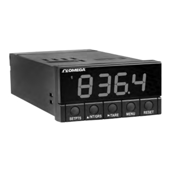
About The Meter 2.4 FRONT OF THE METER Figure 2-1 shows each part of the front of the three-color programmable “Big” LED display meter (Version B). Digital LED Display: -1.9.9.9 or 9.9.9.9 4-digit three color programmable, 21 mm (0.83") high LED display with programmable decimal point. - Page 16 About The Meter METER BUTTONS SETPTS Button In the Run Mode, this button will sequentially recall the previous setpoint settings. As necessary, use the /NT/GRS and /TARE buttons to alter these settings, then press the SETPTS button to store new values. Unless you press the SETPTS, /TARE, or /NT/GRS button within 20 seconds, the...
- Page 17 About The Meter MENU Button In the Run Mode, press the MENU button to terminate the current measuring strain and enter you into the Configuration Mode. Note Only if you have not installed the lock out jumpers on the main board. In the Configuration Mode, press the MENU button to store changes in the nonvolatile memory and then advance you to the next menu item.
-
Page 18: Back Of The Meter
About The Meter 2.5 BACK OF THE METER Figure 2-3 shows the label describing the connectors on the back of the meter. Table 2-2 on the following page gives a brief description of each connector at the back of the meter. POWER &... -
Page 19: Connector Description
About The Meter 2.5 BACK OF THE METER (Continued) Table 2-2. Connector Description Connector Description TB1-1 Setpoint 1: Normally open (N.O.1) connection TB1-2 Setpoint 1: Normally closed (N.C.1) connection TB1-3 Setpoint 1: Common (COM1) connection TB1-4 Setpoint 2: Normally open (N.O.2) connection TB1-5 Setpoint 2: Normally closed (N.C.2) connection TB1-6... -
Page 20: Disassembly
About The Meter The DIP switches are located at the S1 position (refer to Figure 3-2). Use a small instrument, such as a paper clip, to change the switches from open to closed. Table 2-3 lists DIP switch settings at the S1 position required to complete the setup of your meter. Table 2-3. -
Page 21: Getting Started
Getting Started SECTION 3. GETTING STARTED Caution: The meter has no power-on switch, so it will be in operation as soon you apply power. If you power off/on the meter, or perform a hard reset (press the RESET button twice), the meter shows RST , followed by STRN. -
Page 22: Main Board Jumper Positions
Getting Started 3.2 MAIN BOARD POWER JUMPERS (Continued) Figure 3-2 shows the location jumper positions on the main board. MAIN BOARD E D C B A Refer to table 3-1 TP10 TP11 Figure 3-2. Main Board Jumper Positions Attach cable to P1. -
Page 23: S3 Jumper Functions
Getting Started 3.2 MAIN BOARD POWER JUMPERS (Continued) S2 jumpers are used for testing purposes. Do not use as reading errors may result. S3 jumpers are used for the following (refer to Figure 3-2): To enable or disable the front panel push-buttons To allow for an extremely low resistance load for analog output To disable the MENU button To perform factory calibration procedure... -
Page 24: Panel Mounting
Getting Started 3.3 PANEL MOUNTING CONNECTOR LABEL PRODUCT CASE LABEL GASKET FRONT BEZEL Figure 3-4. Meter - Exploded View PANEL THICKNESS 1. Cut a hole in your panel, as 6,4 (.25) MAX shown in Figure 3-4. For 0,8 (.03) MIN specific dimensions refer to Figure 3-5. -
Page 25: Connecting Sensor Inputs
Getting Started 3.4 CONNECTING SENSOR INPUTS Figures 3-6 shows excitation supplied from the meter’s internal supply (50 mA maximum) Select 5, 10, or 12 volt excitation at DIP switch. 20mA Connections with “typical wire colors” +E = Positive Excitation (red) -E = Negative Excitation (black) +S = Positive Signal Input (green) -S = Negative Signal Input (white) -
Page 26: Current Input Connections With Internal Excitation
Getting Started 3.4 CONNECTING SENSOR INPUTS (Continued) Figure 3-8. 4-Wire DC Input Connections with External Excitation Figure 3-9. Current Input Connections with Internal Excitation... -
Page 27: Connecting Main Power
Getting Started 3.4 CONNECTING SENSOR INPUTS (Continued) Figure 3-10. Current Input Connections with External Excitation 3.5 CONNECTING MAIN POWER Connect the AC main power connections as shown in Figure 3-11. WARNING: Do not connect AC power to your device until you have completed all input and output connections. -
Page 28: Main Power Connections - Dc
Getting Started 3.5 CONNECTING MAIN POWER (Continued) Table 3-2 shows the wire color and respective terminal connections for both USA and Europe. Table 3-2. AC-Power Connections WIRE COLORS AC POWER EUROPE ~ AC Line Brown Black ~ AC Neutral Blue White ~ AC Earth Green/Yellow... -
Page 29: Connecting External Tare Switch
Getting Started 3.6 CONNECTING EXTERNAL TARE SWITCH Connect external tare connections as shown in Figure 3-13. 1 2 3 4 1 2 3 4 OPEN 7 8 9 10 11 12 5 6 7 8 CLOSED EXTERNAL TARE SWITCH Figure 3-13. External Tare Connections 3.7 CONNECTING ANALOG AND RELAY OUTPUTS If you have purchased a meter with analog or dual relay or isolated analog output, refer to the following drawings for output connections. -
Page 30: Relay Output Connections
Getting Started 3.7 CONNECTING ANALOG AND RELAY OUTPUTS (Continued) Relay 1 Relay 2 EXTERNAL LOAD COM2 FUSE 1 2 3 4 1 2 3 4 5 6 5 6 7 8 7 8 9 10 11 12 Figure 3-15. Relay Output Connections. 0—20mA 0—10VDC 4—20mA... -
Page 31: Sec
Configuring The Meter SECTION 4. CONFIGURING THE METER Note Refer to Table 6-1 for a summary list of menu configuration. For first-time users: Refer to the QuickStart Manual for basic operation and set-up instructions. INPT 4.1 SELECTING THE INPUT TYPE To select your appropriate input type signal, follow these steps: Note Before proceeding, set the input DIP switch settings at the back of your... -
Page 32: Selecting A Decimal Point Position
Configuring The Meter DEC.P 4.2 SELECTING A DECIMAL POINT POSITION Note Refer to Table 6-1 for a summary list of menu configuration. To select a decimal point display position, follow these steps: Press the MENU button until the meter shows DEC.P . Press the ∂TARE button. -
Page 33: Scaling With Known Loads
Configuring The Meter 4.3.1 Scaling with Known Loads (On-Line Calibration) For maximum resolution, find the maximum signal that will be applied to the Note meter input. • For regular voltage input, refer to the main body of Table 4-1. • For millivolt or milliamp input, refer to the main body of Table 4-2. Set the DIP switch positions as indicated at the top of either Table 4-1 or 4-2. - Page 34 Configuring The Meter 4.3.1 Scaling with Known Loads (On-Line Calibration) (Continued) To scale with known inputs: apply known loads to a transducer connected to a meter, or simulate the transducer output with a voltage or current simulator. To scale with known inputs, follow these steps: Apply a known load equal to approximately 0% of the transducer range.
- Page 35 Configuring The Meter 4.3.1 Scaling with Known Loads (On-Line Calibration) (Continued) Apply a known load equal to approximately 100% of the transducer range. Press the ∂TARE button again. The meter shows the last stored value for Input 2. Press the ∂TARE button once more. The meter shows the actual signal being received.
-
Page 36: Scaling Without Known Loads
Configuring The Meter 4.3.2 Scaling Without Known Loads To scale without known inputs, calculate input values based on the transducer specifications and manually enter them on the front-panel push buttons. The following example assumes load cells with these specifications: Maximum Load: 100.0 lbs Output: 3.1 mV/V... -
Page 37: Using Reading Configuration
Configuring The Meter Determine IN1 and IN!2 input range and resolution. The example selects the 0 to 100 mV range and 10 uV resolution (R.2=4 ). Example: IN1 = (0 mV) x (100 cts/mV) x (1.000) = 0 IN!2 = (31 mV) x (100 cts/mV) x (1.000) = 3100 RD1 = 0000 RD!2 = 100.0 Press MENU button until the meter shows RD.S.O . -
Page 38: Selecting Ratiometric/Non-Ratiometric Operation
Configuring The Meter 4.4.1 Selecting Ratiometric/Non-Ratiometric Operation Press the MENU button until RD.CF displays. Press the ∂TARE button. The meter shows one of the following: R.1=R (Ratiometric reading) (Default - for strain meters) • R.1=N (Non-ratiometric reading - typically for voltage & current transducers) •... -
Page 39: Displaying The Filtered/Unfiltered Input Signal
Configuring The Meter 4.4.3 Displaying the Filtered/Unfiltered Input Signal To display the filtered/unfiltered signal input, follow these steps: Press the MENU button until RD.CF displays, then press the ∂TARE button three times. Press the ∂TARE button from R.2 . One of the following displays: R.3=F (Filtered value) (Default) •... -
Page 40: Selecting A Display Color
Configuring The Meter COLR 4.5 SELECTING A DISPLAY COLOR Refer to Table 6-1 for a summary list of menu configuration. Note Selecting Display Color is not active unless your meter is a Version “B”. To select a display color, follow these steps: Press the MENU button until the meter shows COLR. -
Page 41: Setting Setpoint 1'S Active Band
Configuring The Meter 4.6.1 Setting Setpoint 1's Active Band Press the MENU button until the meter shows S1.CF . Press the ∂TARE button. The meter shows one of the following: S.1=A (Active above the setpoint) (Default) • S.1=B (Active below the setpoint) •... -
Page 42: Assigning Setpoint 1 Values To Net Or Gross Readings
Configuring The Meter 4.6.3 Assigning Setpoint 1 Values to Net or Gross Readings Press the MENU button until S1.CF displays, then press the ∂TARE button twice. Press the ∂TARE button from S.2. The meter shows one of the following: S.3=N Setpoint 1 assigned to net reading (Default) •... -
Page 43: Selecting If Setpoint 2 Is Latched Or Unlatched
Configuring The Meter 4.7.2 Selecting if Setpoint 2 is Latched or Unlatched Press the MENU button until S2.CF displays, then press the ∂TARE button twice. Press the ∂TARE button from S.1. The meter shows one of the following: S.2=U Setpoint 2 to be unlatched (Default) •... -
Page 44: Setting The Setpoint 1 Deadband
Configuring The Meter S1.DB 4.8 SETTING THE SETPOINT 1 DEADBAND Note Refer to Table 6-1 for a summary list of menu configuration. Setpoint 1 Deadband S1.DB is not active unless your meter has dual relay output capabilities. The LED's will display whether the S1.DB is active or not. The Setpoint 1 Default deadband is 0003. -
Page 45: Setting The Setpoint 2 Deadband
Configuring The Meter 4.9 SETTING THE SETPOINT 2 DEADBAND S2.DB Note Refer to Table 6-1 for a summary list of menu configuration. Setpoint 2 Deadband S2.DB is not active unless your meter has dual relay output capabilities. The LED's will display whether the S2.DB is active or not. The Setpoint 2 default deadband is 0003. -
Page 46: Alarm Example
Configuring The Meter SETPOINT SIGNAL LEVEL ACTIVE BELOW ACTIVE ABOVE DEADBAND SETPOINT SIGNAL LEVEL ACTIVE BELOW ACTIVE ABOVE WITH DEADBAND 3 WITH DEADBAND 3 NOTE: DEADBAND WORKS AS HYSTERISIS SETPOINT SIGNAL LEVEL ACTIVE BELOW LATCHED ACTIVE ABOVE LATCHED Figure 4-1. Alarm Example Note To reset latched alarms you must: 1. -
Page 47: Using Output Configuration
Configuring The Meter OT.CF 4.10 USING OUTPUT CONFIGURATION Note Refer to Table 6-1 for a summary list of menu configuration. Output Configuration OT.CF is not active unless your meter has analog output capabilities. The menu will display whether analog output is present or not. Analog output must be ordered at the time of purchase. -
Page 48: Selecting Analog Output As Current Or Voltage
Configuring The Meter 4.10.2 Selecting Analog Output as Current or Voltage Press the MENU button until it shows OT.CF , then press the ∂TARE button twice. Press the ∂TARE button from 0.1. The meter shows one of the following: O.2=C (Analog output = current) (Default) •... -
Page 49: Using Output Scale And Offset
Configuring The Meter OT.S.O 4.11 USING OUTPUT SCALE AND OFFSET Note Refer to Table 6-1 for a summary list of menu configuration. Output Scale and Offset OT.S.O is not active unless your meter has analog output capabilities. The menu will display whether analog output is present or not. Output Scale and Offset OT.S.O scales your analog output to be equal to the meter's display and/or any engineering units you require. - Page 50 Configuring The Meter OT.S.O 4.11 USING OUTPUT SCALE AND OFFSET (Continued) Press the ∂TARE button. The meter shows last previously stored 4-digit number (-1999 through 9999) displays with flashing 4th digit. Press the ßNT/GRS button to change the value of the flashing digit. If you continue to press the ßNT/GRS button, the flashing digit's value continues to change.
-
Page 51: Examples Of Output Scale And Offset
Configuring The Meter 4.11.1 Examples for Output Scale and Offset Example: You want to send 4-20 mA output for 0 to 100.0. The meter has 0.1 degree resolution. Complete the following steps: 1. Press the MENU button until the meter shows OT.S.O. 2. -
Page 52: Using Lock Out Configuration
Configuring The Meter LK.CF 4.12 USING LOCK OUT CONFIGURATION Note Refer to Table 6-1 for a summary list of menu configuration. Use Lock Out Configuration LK.CF for the following: • To enable or disable setpoint changes • To enable or disable the RESET button in the Run Mode •... -
Page 53: Setpoint Display Function: Firmware Version Or Setpoint Value
Configuring The Meter 4.12.3 SETPOINT Display Function: Firmware version or Setpoint value Press the MENU button until the meter shows LK.CF (after OT.S.O ). Press the ∂ ∂ TARE button three times. The meter shows one of the following: • L.3=0 SETPTS button will display setpoint values. •... -
Page 54: Display Messages
Display Messages Table 5-1. Display Messages MESSAGE DESCRIPTION STRN Strain Meter Hard (power on) Reset INPT Input Type DEC.P Decimal Point Position RD.S.O Reading Scale and Offset RD.CF Reading Configuration COLR Display Color S1.CF Setpoint 1 Configuration S2.CF Setpoint 2 Configuration S1.DB Setpoint 1 Deadband S2.DB... -
Page 55: Menu Configuration Displays
Menu Configuration Displays SECTION 6. MENU CONFIGURATION DISPLAYS Not all menu items display on standard meters. Table 6-1. Menu Configuration Displays (Defaults in Bold and Italics) ∂TARE ßNT/GRS MENU 100M ( Default ) Show input choices: ±50M INPT ±5V 0-20 FFFF ( Default ) Show current decimal F.FFF... -
Page 56: Sec
Menu Configuration Displays SECTION 6. MENU CONFIGURATION DISPLAYS (Continued) Table 6-1. Menu Configuration Displays (Continued) (Defaults in Bold and Italics) ßNT/GRS ∂TARE MENU R.1=R (Ratiometric Reading) R.1= Reading Configuration R.1=N (Non-ratiometric reading) RD.CF R.2=0 (1 µV resolution for unipolar R.2= &... - Page 57 Menu Configuration Displays SECTION 6. MENU CONFIGURATION DISPLAYS (Continued) Table 6-1. Menu Configuration Displays (Continued) (Defaults in Bold and Italics) ßNT/GRS ∂TARE MENU Press to scroll to the next Press to change the value of the flashing Setpoint 1 Deadband digit to the right digit S1.DB...
-
Page 58: Run Mode Displays
Menu Configuration Displays SECTION 6. MENU CONFIGURATION DISPLAYS (Continued) Table 6-1. Menu Configuration Displays (Continued) (Defaults in Bold and Italics) ßNT/GRS ∂TARE MENU RS=E (Enable RESET button in the Run Mode) Lock Out Configuration RS=D (Disable RESET button in the Run Mode) LK.CF SP=E (Enable setpoint changes) SP=D (Disable setpoint changes) -
Page 59: Setpoint Configuration Displays
Setpoint Configuration Displays SECTION 7. SETPOINT CONFIGURATION DISPLAYS Table 7-1. Setpoint Configuration Displays ßNT/GRS ∂ ∂ TARE MENU Description SETPOINT 1 Press to scroll to Press to change Select from -1999 the next digit to the the value of the through 9999 right flashing digit... -
Page 60: Sec
Specifications SECTION 8. SPECIFICATIONS SIGNAL INPUT Input Ranges: 0-100 mV, ± 50 mV, 0-10 V, ± 5 V, 0-20 mA, 4-20 mA Isolation: Dielectric strength to 2500V transient per 3mm spacing based on EN 61010 for 260Vrms or DC working voltage Noise Rejection: Normal Mode Rejection (NMR) = 60 dB Common Mode Rejection (CMR) = 120 dB... -
Page 61: Sec
Specifications SECTION 8. SPECIFICATIONS (Continued) ALARM OUTPUTS (if applicable) 2 Form "C" on/off relays. Configurable for latched and unlatched by software. Max current: 5 AMPS, resistive load Max voltage: 250 Vac or 30 Vdc ANALOG OUTPUT (if applicable) Signal Type: Current or voltage Signal Level: Current: 10 V max compliance at 20 mA output... -
Page 62: Panel Cutout
Specifications SECTION 8. SPECIFICATIONS (Continued) INPUT POWER INFORMATION AC units 115/230 V~(AC) + 10%, 50/60 Hz 9.5 W max, power consumption (Non-Isolated Analog Out) 11.0 W max, power consumption (Isolated Analog Out) DC units 10-32 Vdc or 26-56 Vdc, 8 W Do not use a combination of dc power and internal excitation or Isolated Analog Out, unless using dc power of 20-32... -
Page 63: Color Chart For Dc Power
Specifications SECTION 8. SPECIFICATIONS (Continued) Table 8-1. COLOR CHART FOR DC POWER COLOR HIGH BRIGHTNESS MEDIUM & LOW BRIGHTNESS Sensor Excitation: Any combination of Sensor Excitation 24 V @ 25 mA, and Analog Output 12 V, 10 V, 5 V @ 35 mA Max 24 V @ 25 mA, Analog Output: 12 V @ 35 mA Max... -
Page 64: Meter Dimensions/Panel Cutout
Specifications SECTION 8. SPECIFICATIONS (Continued) 48,0 (1.89) 96,0 (3.78) FRONT BEZEL 20,3 (.80) RETAINER CASE REAR COVER TOP VIEW SIDE VIEW PANEL THICKNESS 6,4 (.25) MAX 0,8 (.03) MIN R(.06) 45,00 + 0,61/-0,00 (1.772 + .024/–.000) 4 PLCS 92,00 + 0,81/–0,00 (3.622 + .032/–.000) NOTE: Dimensions in Millimeters (Inches) Figure 8-1 Meter Dimensions/ Panel Cutout... -
Page 65: Factory Preset Values
Factory Preset Values SECTION 9. FACTORY PRESET VALUES Table 9-1. Factory Preset Values MENU ITEM FACTORY PRESET VALUES INPT Input Type: 0-100 (0-100 mV) input DEC.P Decimal Point Position: FFFF RD.S.O Reading Scale and Offset: 0-100 mV = 0-1000 RD.CF Reading Configuration: R.1=R (Ratiometric) R.2=4 (10 µV resolution for unipolar &... -
Page 66: Sec 10 Ce Approval Information
CE APPROVALS INFORMATION This product conforms to EMC 2014/30/EU (EMC directive) Electrical Safety: 2014/35/EU (Low Voltage Directive) Safety requirements for electrical equipment for measurement, control and laboratory. Double Insulation Pollution Degree 2 Dielectric withstand Test per 1 min • Power to Input/Output: 2300 Vac (3250 Vdc) •... - Page 67 Authorized Return (AR) number immediately upon phone or written request. Upon examination by OMEGA, if the unit is found to be defective, it will be repaired or replaced at no charge. OMEGA’s WARRANTY does not apply to defects resulting from any action of the purchaser, including but not limited to mishandling, improper interfacing, operation outside of design limits, improper repair, or unauthorized modification.
- Page 68 Where Do I Find Everything I Need for Process Measurement and Control? OMEGA…Of Course! Shop on line at omega.com TEMPERATURE Thermocouple, RTD & Thermistor Probes, Connectors, Panels & Assemblies Wire: Thermocouple, RTD & Thermistor Calibrators & Ice Point References Recorders, Controllers & Process Monitors...
Need help?
Do you have a question about the DP25B-S and is the answer not in the manual?
Questions and answers