
Related Manuals for Omega DP-7600


Summary of Contents for Omega DP-7600
- Page 1 User’ s Guide Shop online at omega.com e-mail: info@omega.com For latest product manuals: omegamanual.info DP-7600 High Speed Strain Gauge Readout This datasheet has been downloaded from http://www.digchip.com at this page...
- Page 2 Toll Free in United Kingdom: 0800-488-488 e-mail: sales@omega.co.uk It is the policy of OMEGA to comply with all worldwide safety and EMC/EMI regulations that apply. OMEGA is constantly pursuing certification of its products to the European New Approach Directives. OMEGA will add the CE mark to every appropriate device upon certification.
- Page 3 OMEGA be liable for consequential, incidental or special damages. CONDITIONS: Equipment sold by OMEGA is not intended to be used, nor shall it be used: (1) as a “Basic Component” under 10 CFR 21 (NRC), used in or with any nuclear installation or activity;...
-
Page 4: Table Of Contents
TABLE OF CONTENTS DESCRIPTION ......... 1 SWITCH FUNCTIONS . - Page 5 EXCITATION SETTINGS....... . . 14 DP-7600 BACK VIEW ........14 DP-7600 REAR TERMINATIONS .
-
Page 6: Description
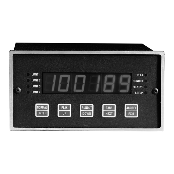
SWITCH FUNCTIONS: There are five switches located behind the front lens of the model DP-7600. The front panel switches appear as shown below. The text located at the top half of each switch (i.e., NORMAL, PEAK, RUNOUT, TARE, ABS/REL) indicates that particular switch’s function when the unit is in data acquisition and display mode. - Page 7 Data Acquisition & Display : Press to set the display mode for actual reading. Setup & Calibration Modes : Press to record a complete setting and advance to the next setup. Data Acquisition & Display : Press to set the display mode for peak. Setup &...
-
Page 8: Led Indicators
LED INDICATORS: Limit 1 Illuminates when the display reading exceeds the set limit, and in the setup mode when establishing the limit. Limit 2 Illuminates when the display reading exceeds the set limit, and in the setup mode when establishing the limit. Limit 3 Illuminates when the display reading exceeds the set limit, and in the setup mode when establishing the limit. -
Page 9: Limit Programming
to advance to the next parameter. At any time during the setup sequence the EXIT switch can be pressed to leave the setup mode and save the current settings. If the setup sequence is completed the unit will save all settings and automatically return to data acquisition and display mode. -
Page 10: Filter Setup
Once the proper baud rate is selected press the ENTER switch to advance to the next setup. ECHO SETUP The model DP-7600 can be programmed to automatically re-transmit (echo) characters received on its serial communications input. A value of one enables the echo feature; conversely, programming a zero will disable it. -
Page 11: Legend Setup
LEGEND SETUP The DP-7600 can append a user selectable engineering units string to read- ings transmitted from the unit. This feature allows direct terminal readout in engineer- ing units, or easier unit identification in multi-unit applications. Program the legend number to the number corresponding with desired units as shown in the table below. -
Page 12: Calibration
CALIBRATION: The calibration mode is entered by pressing the Normal [Enter] and ABS/REL [Exit] switches simultaneously. Note: This is the only method to check or change the calibration of this unit externally. PROTECTION CODE Before any calibration can be performed on the unit a unique security code must be entered. -
Page 13: Serial Communications
Both RS232 and RS485 serial communication options are available for the DP-7600. The baud rate is user selectable, and can range from 300 to 38.4K baud. The unit uses a N,8,1 character data format (no parity, 8 data bits, 1 stop bit). -
Page 14: Echo
: “BYE ad 0[CR]” Note: Remember [CR] represents a carriage return character. The following is a list of the serial commands available on the DP-7600. Each com- mand string is shown in quotes, a parameter/number field is represented by X (first) or Y (second), the sign, where needed, is shown as a lower case s(s). -
Page 15: Line Feed
The address enable command, in conjunction with the address disable command, can be used to network multiple DP-7600 units. Once a unit’s address has been enabled it will respond to all incoming commands until the unit’s address is disabled. When the address enabled command is executed by a DP-7600 it responds with “HELLO ae... -
Page 16: Test Message
(since contention could result in scrambled data at the printer). To compensate for this, the model DP-7600 allows unit to “take turns” on the same serial bus. This is done by enabling transmission of a special non-printable character at the end of a reading string;... -
Page 17: Reading Mode
READING MODE: “PV X[CR]” The display reading mode can be set using this command. X = 0: Display is set for reading only X = 1: Display is set for peak X = 2: Display is set for runout ABSOLUTE OR RELATIVE “AR X[CR]” Allows changing of the display mode between absolute and relative. -
Page 18: Remote Inputs
Example: Assume we want a high limit, normal (reading), active on channel one; then, YY = 01 OR’ed 08 = 09 HEX (NOTE: unlike most serial command parameters, this is not ASCII). REMOTE INPUTS: Seven logic level, active-low, remote inputs are located on the rear of the unit for inter- facing to programmable logic controllers etc.. -
Page 19: Dp-7600 Sensitivity Settings
DP-7600. Also assume that the excitation required 10V; therefore, the full-scale input to the unit will be 5mV at 10,000 pound, and the sensitivity switches located on the rear of the DP-7600 should be set for 5.1mV full-scale (S1 - S3 open). -
Page 20: Dp-7600 Rear Terminations
DP-7600 REAR TERMINATIONS TB1 (POWER INPUT - BOTTOM BOARD) AC LINE AC NEUTRAL EARTH GROUND TB2 (TOP BOARD) TB3 (BOTTOM BOARD) LIMIT 1 SHIELD LIMIT 2 -15V LIMIT 3 ANALOG OUTPUT LIMIT 4 -RCAL2 NORMAL MODE +RCAL2 DATA REQUEST -SIGNAL2... -
Page 21: Schematic (Dp-7600 Top Board)
SCHEMATIC (DP-7600 Top Board) - Page 22 SCHEMATIC (DP-7600 Top Board)
- Page 23 SCHEMATIC (DP-7600 Top Board)
-
Page 24: Schematic (Dp-7600 Bottom Board)
SCHEMATIC (DP-7600 Bottom Board) - Page 25 SCHEMATIC (DP-7600 Bottom Board)
-
Page 26: Schematic (Dp-7600 Analog Input Option Board)
SCHEMATIC (DP-7600 Analog Input Option Board) -
Page 27: Schematic (Dp-7600 Output Option Board)
SCHEMATIC (DP-7600 Output Option Board) -
Page 28: Schematic (Dp-7600 Rs232/Rs485 Option Board)
SCHEMATIC (DP-7600 RS232/RS485 Option Board) -
Page 29: Dimensions
DIMENSIONS 6” INCLUDING I/O CONNECTOR... -
Page 30: Mounting
MOUNTING Customers Panel with Cutout to mount Omega Instrument I/O Connectors Supplied by Omega Number and Style Vary Mounting Straps Supplied by Omega... - Page 31 Where Do I Find Everything I Need for Process Measurement and Control? OMEGA…Of Course! Shop online at omega.com TEMPERATURE Thermocouple, RTD & Thermistor Probes, Connectors, Panels & Assemblies Wire: Thermocouple, RTD & Thermistor Calibrators & Ice Point References Recorders, Controllers & Process Monitors...
Need help?
Do you have a question about the DP-7600 and is the answer not in the manual?
Questions and answers