
Related Manuals for Mitsubishi QD75M1


Summary of Contents for Mitsubishi QD75M1
- Page 1 Type QD75M Positioning Module User's Manual (Details) Mitsubishi Programmable QD75M1 Logic Controller QD75M2 QD75M4...
-
Page 2: Safety Instructions
SAFETY INSTRUCTIONS (Always read these instructions before using this equipment.) Before using this product, please read this manual and the relevant manuals introduced in this manual carefully and pay full attention to safety to handle the product correctly. The instructions given in this manual are concerned with this product. For the safety instructions of the programmable logic controller system, please read the CPU module User's Manual. - Page 3 [Design Instructions] CAUTION Do not bundle or adjacently lay the control wire or communication cable with the main circuit or power wire. Separate these by 100mm (3.94in.) or more. Failure to observe this could lead to malfunctioning caused by noise. [Mounting Instructions] CAUTION Use the PLC within the general specifications environment given in this manual.
- Page 4 [Startup/Maintenance Instructions] CAUTION Never disassemble or modify the module. Failure to observe this could lead to trouble, malfunctioning, injuries or fires. Always turn all phases of the power supply OFF externally before installing or removing the module. Failure to turn all phases OFF could lead to module trouble or malfunctioning. Before starting test operation, set the parameter speed limit value to the slowest value, and make sure that operation can be stopped immediately if a hazardous state occurs.
-
Page 5: Revisions
This manual confers no industrial property rights or any rights of any other kind, nor does it confer any patent licenses. Mitsubishi Electric Corporation cannot be held responsible for any problems involving industrial property rights which may occur as a result of using the contents noted in this manual. -
Page 6: Table Of Contents
INTRODUCTION Thank you for purchasing the Mitsubishi general-purpose programmable logic controller MELSEC-Q Series. Always read through this manual, and fully comprehend the functions and performance of the Q Series PLC before starting use to ensure correct usage of this product. - Page 7 3.2.3 QD75 sub functions and common functions ..................3- 8 3.2.4 Combination of QD75 main functions and sub functions..............3- 10 3.3 Specifications of input/output signals with PLC CPU ................3- 12 3.3.1 List of input/output signals with PLC CPU..................3- 12 3.3.2 Details of input signals (QD75 PLC CPU) ..................
- Page 8 5.2.8 Servo adjustment parameters......................5- 64 5.2.9 Servo expansion parameters......................5- 74 5.2.10 Servo expansion parameters 2...................... 5- 78 5.3 List of positioning data ..........................5- 82 5.4 List of block start data ..........................5- 98 5.5 List of condition data ..........................5-104 5.6 List of monitor data..........................
- Page 9 Section 2 Control Details and Setting 8. OPR Control 8- 1 to 8- 14 8.1 Outline of OPR control ..........................8- 2 8.1.1 Two types of OPR control ......................... 8- 2 8.2 Machine OPR ............................8- 4 8.2.1 Outline of the machine OPR operation..................... 8- 4 8.2.2 Machine OPR method........................
- Page 10 9.2.21 JUMP instruction ........................... 9-111 9.2.22 LOOP............................. 9-113 9.2.23 LEND ............................. 9-114 10. High-Level Positioning Control 10- 1 to 10- 26 10.1 Outline of high-level positioning control ....................10- 2 10.1.1 Data required for high-level positioning control................10- 3 10.1.2 "Block start data" and "condition data" configuration..............10- 4 10.2 High-level positioning control execution procedure ................
- Page 11 12. Control Sub Functions 12- 1 to 12- 92 12.1 Outline of sub functions ........................12- 2 12.1.1 Outline of sub functions ........................ 12- 2 12.2 Sub functions specifically for machine OPR ..................12- 4 12.2.1 OPR retry function......................... 12- 4 12.2.2 OP shift function ...........................
- Page 12 14. Dedicated Instructions 14- 1 to 14- 18 14.1 List of dedicated instructions ....................... 14- 2 14.2 Interlock during dedicated instruction is executed ................14- 2 14.3 PSTRT1, PSTRT2, PSTRT3, PSTRT4....................14- 3 14.4 TEACH1, TEACH2, TEACH 3, TEACH 4 ................... 14- 7 14.5 PFWRT..............................
- Page 13 Appendix 7 Explanation of positioning terms ..................Appendix- 70 Appendix 8 Positioning control troubleshooting ................Appendix- 94 Appendix 9 List of buffer memory addresses.................Appendix-100 Appendix 10 External dimension drawing ..................Appendix-112 INDEX Index- 1 to Index - 14 INDEX..............................Index - 1 A - 12...
-
Page 14: About Manuals
About Manuals The following manuals are also related to this product. In necessary, order them by quoting the details in the tables below. Related Manuals Manual Number Manual Name (Model Code) Type QD75M Positioning Module User's Manual (Hardware) Describes the performance, specifications, Input interface, component names, and startup procedure of IB-0300031 the respective positioning modules: Type QD75M (1CT750) -
Page 15: Generic Terms And Abbreviations
PLC CPU Generic term for PLC CPU on which QD75 can be mounted. QD75 Generic term for positioning module QD75M1, QD75M2 and QD75M4. The module type is described to indicate a specific module. MR-H-BN Servo amplifier: Abbreviation for MR-H-BN/MR-H B. -
Page 16: Section 1 Product Specifications And Handling
Section 1 Product Specifications and Handling Section 1 is configured for the following purposes (1) to (5). (1) To understand the outline of positioning control, and the QD75 specifications and functions (2) To carry out actual work such as installation and wiring (3) To set parameters and data required for positioning control (4) To create a sequence program required for positioning control (5) To understand the memory configuration and data transmission process... - Page 17 MEMO...
- Page 18 Chapter 1 Product Outline The purpose and outline of positioning control using QD75 are explained in this chapter. Reading this chapter will help you understand what can be done using the positioning system and which procedure to use for a specific purpose. By understanding "What can be done", and "Which procedure to use"...
-
Page 19: Product Outline 1- 1 To
1 PRODUCT OUTLINE MELSEC-Q 1.1 Positioning control 1.1.1 Features of QD75 The features of the QD75 are shown below. (1) Availability of one, two, and four axis modules (a) One, two and four axis positioning modules are available. They can be selected according to the PLC CPU type and the number of required control axes. - Page 20 (4) SSCNET makes the connection to the servo amplifier possible (a) The QD75 can be directly connected to the servo amplifier using the MELSERVO (Mitsubishi's servo amplifier: MR-H-BN, MR-H-BN4, MR-J2-B, MR-J2S-B, MR-J2-Jr, MR-J2M-B) and SSCNET. (b) Because the SSCNET cable is used to connect the QD75 and the servo amplifier, or servo amplifiers, saving wiring can be realized.
- Page 21 1 PRODUCT OUTLINE MELSEC-Q (6) Control can be realized with the mechanical system input The external inputs, such as external start, stop, and speed/position switching is used to perform the positioning control without using the PLC program. (7) Easy maintenance Each QD75 positioning module incorporates the following improvements in maintainability: (a) Data such as the positioning data and parameters can be stored on a flash...
-
Page 22: Purpose And Applications Of Positioning Control
1 PRODUCT OUTLINE MELSEC-Q 1.1.2 Purpose and applications of positioning control "Positioning" refers to moving a moving body, such as a workpiece or tool (hereinafter, generically called "workpiece") at a designated speed, and accurately stopping it at the target position. The main application examples are shown below. Punch press (X, Y feed positioning •... - Page 23 1 PRODUCT OUTLINE MELSEC-Q Lifter (Storage of Braun tubes onto aging rack) • During the aging process of Braun tubes, Unloader storage onto the rack is carried out by Loader/unloader positioning with the AC servo. • The up/down positioning of the lifter is carried B conveyor Aging rack out with the 1-axis servo, and the horizontal...
-
Page 24: Mechanism Of Positioning Control
Outputs the positioning data of the motor data and etc. to the QD75 by the SSCNET. Motor Carries out the actual work according to commands from the servo. Workpiece (Note): For QD75M1, 2 and 4, use SW2D5C-QD75P or later of the GX Configurator. 1 - 7... -
Page 25: Overview Of Positioning Control Functions
1 PRODUCT OUTLINE MELSEC-Q 1.1.4 Overview of positioning control functions The outline of the "overview of positioning control" and "overview of individual positioning control and continuous positioning control", "overview of block positioning control" and "overview of acceleration/deceleration processing control" is shown below. ositioning control An overview of positioning using positioning data described below. - Page 26 1 PRODUCT OUTLINE MELSEC-Q (Note) (b) 2-axis linear interpolation control This controls interpolation along a linear locus from the start point address (current stop position) defined by two axes. [Control using the absolute system] 1) This performs linear interpolation using two axes from the start point address to the endpoint address.
- Page 27 1 PRODUCT OUTLINE MELSEC-Q (Note) (2) Circular interpolation control There are two types of circular interpolation controls: circular interpolation with a specified sub point and circular interpolation with the specified center point. (a) Circular interpolation with a specified sub point Circular interpolation is performed using the specified endpoint address and sub point (passing point) address.
- Page 28 1 PRODUCT OUTLINE MELSEC-Q (3) Fixed-feed control This performs positioning for the specified increment of travel. The fixed-feed control includes 1-axis control and 2-axis control through linear interpolation using the specified two axes. Positioning direction Operation timing [1-axis fixed-feed control] Stop position Reverse direction Forward direction...
- Page 29 1 PRODUCT OUTLINE MELSEC-Q (5) Speed-position switching control This starts positioning under speed control, and switches to position control according to the input of the QD75 speed-position switching signal and perform positioning for the specified increment of travel. Specified travel Speed control Position control increment...
- Page 30 1 PRODUCT OUTLINE MELSEC-Q ndividual positioning control and continuous positioning control The QD75 performs positioning according to the user-set positioning data, which is a set of information comprised of the control method (position control, speed control, speed-position switching control), positioning address, operation pattern, and so on. Up to 600 of positioning data are assigned respectively to positioning data Nos.
- Page 31 1 PRODUCT OUTLINE MELSEC-Q (2) Continuous positioning control (operation pattern = 01: positioning continues) The operation stops temporarily upon the completion of positioning for the specified positioning data, and then continues with the next positioning data number. This is specified when performing positioning in which the direction changes because of multiple positioning data items having consecutive positioning data numbers.
- Page 32 1 PRODUCT OUTLINE MELSEC-Q (3) Continuous path control (operation pattern = 11: positioning continue) After executing positioning using the specified positioning data, the operation changes its speed to that of the next positioning data number and continues positioning. This is specified when continuously executing multiple positioning data items having consecutive positioning data numbers at a specified speed.
- Page 33 1 PRODUCT OUTLINE MELSEC-Q lock positioning control Block positioning is a control that continuously executes the positioning of specified blocks. One block equivalent to a series of positioning data up to the completion of positioning (operation pattern = 00) by Independent or continuous positioning control. A maximum of 50 blocks per axis can be specified.
- Page 34 1 PRODUCT OUTLINE MELSEC-Q Overview of acceleration/deceleration processing control Acceleration/deceleration processing for the positioning processing, manual pulse- generator processing, OPR processing and JOG processing is performed using the user-specified method, acceleration time and deceleration time. (1) Acceleration/deceleration method There are two types of acceleration and deceleration processing: the automatic trapezoidal acceleration/deceleration processing method and S-pattern acceleration/deceleration processing method.
-
Page 35: Outline Design Of Positioning System
1 PRODUCT OUTLINE MELSEC-Q 1.1.5 Outline design of positioning system The outline of the positioning system operation and design, using the QD75, is shown below. (1) Positioning system using QD75 Servo QD75 MR-H-BN/MR-H B/MR-J2- B/MR-J2S- B/MR-J2-Jr/MR-J2M-B motor Positioning command Positioning Speed Current Inverter... -
Page 36: Communicating Signals Between Qd75 And Each Module
1 PRODUCT OUTLINE MELSEC-Q 1.1.6 Communicating signals between QD75 and each module The outline of the signal communication between the QD75 (positioning module) and PLC CPU, peripheral device and servo amplifier, etc., is shown below. (A peripheral device communicates with the QD75 via the PLC CPU to which it is connected) QD75 PLC CPU... - Page 37 1 PRODUCT OUTLINE MELSEC-Q QD75 PLC CPU The QD75 and PLC CPU communicate the following data via the base unit. Direction QD75 PLC CPU PLC CPU QD75 Communication Signal indicating QD75 state Signal related to commands • QD75 READY signal •...
- Page 38 1 PRODUCT OUTLINE MELSEC-Q QD75 Manual pulse generator The QD75 and manual pulse generator communicate the following data via the external device connection connector. (The manual pulse generator should be connected to an external device connection connector for axis 1 or for axes 1 and 2.) Direction QD75 Manual pulse generator...
-
Page 39: Flow Of System Operation
1 PRODUCT OUTLINE MELSEC-Q 1.2 Flow of system operation 1.2.1 Flow of all processes The positioning control processes, using the QD75, are shown below. GX Configurator-QP QD75 Servo, etc. PLC CPU GX Developer Understand the functions and performance, and determine the positioning operation method Design (system design) Installation, wiring... - Page 40 1 PRODUCT OUTLINE MELSEC-Q The following work is carried out with the processes shown on the previous page. Details Reference • Chapter 1 • Understand the product functions and usage methods, the configuration devices Chapter 2 • and specifications required for positioning control, and design the system. Chapter 3 •...
-
Page 41: Outline Of Starting
1 PRODUCT OUTLINE MELSEC-Q 1.2.2 Outline of starting The outline for starting each control is shown with the following flowchart. It is assumed that each module is installed, and the required system configuration, etc., has been prepared. Flow of starting Installation and connection of module Preparation Setting of hardware... - Page 42 1 PRODUCT OUTLINE MELSEC-Q Setting method : Indicates the PLC program that must be created. <GX Configurator-QP> Write Set with peripheral S/W Set the parameter and data for executing main function, and the sub functions that need to be set beforehand. QD75 <GX Developer>...
-
Page 43: Outline Of Stopping
1 PRODUCT OUTLINE MELSEC-Q 1.2.3 Outline of stopping Each control is stopped in the following cases. (1) When each control is completed normally. (2) When the Servo READY signal is turned OFF. (3) When the PLC READY signal is turned OFF. (When a stop error occurs "parameter error", "watch dog error"... -
Page 44: Outline For Restarting
1 PRODUCT OUTLINE MELSEC-Q Reference Provide the emergency stop circuits external to the servo system to prevent cases where danger may result from abnormal operation of the overall in the event of a power supply fault or servo system failure. 1.2.4 Outline for restarting When a stop cause has occurred during operation with position control causing the axis to stop, positioning to the end point of the positioning data can be restarted from... - Page 45 1 PRODUCT OUTLINE MELSEC-Q [For incremental system] (a) Operation when the axis 1 movement amount is 300 and the axis 2 movement amount is 600. Axis 1 Axis 1 Stop position due to stop cause Stop position Stop position due to stop cause after restart Positioning Designated end...
- Page 46 Chapter 2 System Configuration In this chapter, the general image of the system configuration of the positioning control using QD75, the configuration devices, applicable CPU and the precautions of configuring the system are explained. Prepare the required configuration devices to match the positioning control system. 2.1 General image of system .....................2- 2 2.2 Component list......................2- 4 2.3 Applicable system......................2- 5...
-
Page 47: General Image Of System
2 SYSTEM CONFIGURATION MELSEC-Q 2.1 General image of system The general image of the system, including the QD75, PLC CPU and peripheral devices is shown below. (The Nos. in the illustration refer to the "No." in section "2.2 Component list". Main base unit Extension cable... - Page 48 2 SYSTEM CONFIGURATION MELSEC-Q Servo Motor amplifer Manual pulse generator SSCNET cable Machine system inputs (switches) Cable Upper/lower stroke limit switch External-command signal/switching signal Stop signal Near-point dog signal Peripheral device GX Configurator Personal computer -QD75P-E (For details, refer to GX Configurator -QP Operating Manual.) 2 - 3...
-
Page 49: Component List
Servo amplifier – (Prepared by user) (Prepared by user) Manual pulse – generator Recommended: MR-HDP01 (Mitsubishi Electric) SSCNET cable (For connecting (Prepared by user) between the QD75 – Cables are needed to connect the QD75 with the servo amplifier. and the servo... -
Page 50: Applicable System
2 SYSTEM CONFIGURATION MELSEC-Q 2.3 Applicable system The QD75 can be used in the following system. (1) Applicable modules and the number of installable modules The following table indicates the CPU modules and network modules (for remote I/O station) usable with the QD75 and the number of installable modules. Applicable modules Number of installable modules Remarks... -
Page 51: How To Check The Function Version, Serial No
2 SYSTEM CONFIGURATION MELSEC-Q 2.4 How to check the function version, serial No. The function version and the SERIAL No. of the QD75 can be checked in the following methods. [1] Method using the rated plate on the module side face [2] Method using the software [1] Method using the rated plate on the module side face Check the alphabet of "SERIAL". - Page 52 Chapter 3 Specifications and Functions The various specifications of the QD75 are explained in this chapter. The "General specifications", "Performance specifications", "List of functions", "Specifications of input/output signals with PLC CPU", and the "Specifications of input/output interfaces with external devices", etc., are described as information required when designing the positioning system.
-
Page 53: Performance Specifications
3 SPECIFICATIONS AND FUNCTIONS MELSEC-Q 3.1 Performance specifications Model QD75M1 QD75M2 QD75M4 Item No. of control axes 1 axis 2 axes 4 axes 2-, 3-, or 4-axis linear 2-axis linear interpolation Interpolation function None interpolation 2-axis circular interpolation 2-axis circular interpolation... - Page 54 MR-H-BN/MR-H-BN4. MR-J2HBUS M-A (0.5m(1.64ft.), 1m(3.28ft.), 5m(16.4ft.) ) • MR-J2CN1-A: connector set (sold separately) SSCNET cable over all length (m) Internal current consumption QD75M1 : 0.40A QD75M2 : 0.40A QD75M4 : 0.40A (5VDC) Flash ROM write count Max. 100000 times No. of occupied I/O points (points) 32 (I/O assignment: 32 points for intelligent function module) ×...
-
Page 55: List Of Functions
3 SPECIFICATIONS AND FUNCTIONS MELSEC-Q 3.2 List of functions 3.2.1 QD75 control functions The QD75 has several functions. In this manual, the QD75 functions are categorized and explained as follows. Main functions (1) OPR control "OPR control" is a function that established the start point for carrying out positioning control, and carries out positioning toward that start point. - Page 56 3 SPECIFICATIONS AND FUNCTIONS MELSEC-Q Main functions Sub functions OPR control Control registered in QD75 (Functions characteristic to machine OPR) [Positioning start No.] retry function [9001] Machine OPR OP shift function [9002] Fast OPR <Functions that compensate control> Backlash compensation function Electronic gear function Major positioning control Control using "Positioning data"...
-
Page 57: Qd75 Main Functions
3 SPECIFICATIONS AND FUNCTIONS MELSEC-Q 3.2.2 QD75 main functions The outline of the main functions for positioning control with the QD75 is described below. (Refer to "Section 2" for details on each function.) Reference Main functions Details section Mechanically establishes the positioning start point using Machine OPR control a near-point dog or stopper. - Page 58 3 SPECIFICATIONS AND FUNCTIONS MELSEC-Q Reference Main functions Details section With one start, executes the positioning data in a random block Block start (Normal start) 10.3.2 with the set order. Carries out condition judgment set in the "condition data" for the designated positioning data, and then executes the "block start data".
-
Page 59: Qd75 Sub Functions And Common Functions
3 SPECIFICATIONS AND FUNCTIONS MELSEC-Q 3.2.3 QD75 sub functions and common functions Sub functions The functions that assist positioning control using the QD75 are described below. (Refer to "Section 2" for details on each function. Reference Sub function Details section This function retries the OPR with the upper/lower limit switches during OPR. - Page 60 3 SPECIFICATIONS AND FUNCTIONS MELSEC-Q Reference Sub function Details section This function temporarily stops the operation to confirm the positioning operation during debugging, etc. Step function 12.7.1 The operation can be stopped at each "automatic deceleration" or "positioning data". This function stops (decelerates to a stop) the positioning being Skip function executed when the skip signal is input, and carries out the next 12.7.2...
-
Page 61: Combination Of Qd75 Main Functions And Sub Functions
3 SPECIFICATIONS AND FUNCTIONS MELSEC-Q 3.2.4 Combination of QD75 main functions and sub functions With positioning control using the QD75, the main functions and sub functions can be combined and used as necessary. A list of the main function and sub function combinations is given below. - Page 62 3 SPECIFICATIONS AND FUNCTIONS MELSEC-Q Functions that Functions that limit Functions that change compensate Other functions control control details control REMARK • The "common functions" are functions executed as necessary. (These are not combined with the control.) • "High-level positioning control" is a control used in combination with the "major positioning control".
-
Page 63: Specifications Of Input/Output Signals With Plc Cpu
3 SPECIFICATIONS AND FUNCTIONS MELSEC-Q 3.3 Specifications of input/output signals with PLC CPU 3.3.1 List of input/output signals with PLC CPU The QD75 uses 32 input points and 32 output points for exchanging data with the PLC CPU. The input/output signals when the QD75 is mounted in slot No. 0 of the main base unit are shown below. -
Page 64: Details Of Input Signals (Qd75 Plc Cpu)
3 SPECIFICATIONS AND FUNCTIONS MELSEC-Q 3.3.2 Details of input signals (QD75 PLC CPU) The ON/OFF timing and conditions of the input signals are shown below. Device Signal name Details QD75 READY ON: READY • When the PLC READY signal [Y0] turns from OFF to ON, the parameter setting OFF: Not READY/ range is checked. - Page 65 3 SPECIFICATIONS AND FUNCTIONS MELSEC-Q Important : "Positioning complete" of the QD75 refers to the point when the pulse output from QD75 is completed. Thus, even if the QD75's positioning complete signal turns ON, the system may continue operation. 3 - 14...
- Page 66 3 SPECIFICATIONS AND FUNCTIONS MELSEC-Q 3.3.3 Detail of output signals (PLC CPU QD75) The ON/OFF timing and conditions of the output signals are shown below. Device No. Signal name Details PLC READY OFF: (a) This signal notifies the QD75 that the PLC CPU is normal. PLC READY OFF •...
-
Page 67: Specifications Of Interfaces With External Devices
3 SPECIFICATIONS AND FUNCTIONS MELSEC-Q 3.4 Specifications of interfaces with external devices 3.4.1 Electrical specifications of input signals Input specifications Rated input Working Input Response Signal name voltage/current voltage range voltage/current voltage/current resistance time Stop signal (STOP) Upper limit signal 19.2 to 17.5VDC or more/ 7VDC or less/... -
Page 68: Signal Layout For External Device Connection Connector
3.4.2 Signal layout for external device connection connector The specifications of the connector section, which is the input/output interface for the QD75 and external device, are shown below. The signal layout for the QD75 external device connection connector is shown. QD75M1 QD75M2 QD75M4 QD75M4... -
Page 69: List Of Input Signal Details
3 SPECIFICATIONS AND FUNCTIONS MELSEC-Q 3.4.3 List of input signal details The details of each QD75 external device connection connector are shown below: Pin No. Signal details Signal name (Negative logic is selected by external input signal logic selection) AX1 AX2 AX3 AX4 •... -
Page 70: Interface Internal Circuit
3 SPECIFICATIONS AND FUNCTIONS MELSEC-Q 3.4.4 Interface internal circuit The outline diagrams of the internal circuits for the QD75M1 external device connection interface are shown below. (1) Input External wiring Pin No. Internal circuit Signal name Need for wiring When Upper-limit... - Page 71 3 SPECIFICATIONS AND FUNCTIONS MELSEC-Q MEMO 3 - 20...
- Page 72 Chapter 4 Installation, Wiring and Maintenance of the Product The installation, wiring and maintenance of the QD75 are explained in this chapter. Important information such as precautions to prevent malfunctioning of the QD75, accidents and injuries as well as the proper work methods are described. Read this chapter thoroughly before starting installation, wiring or maintenance, and always following the precautions.
-
Page 73: Outline Of Installation, Wiring And Maintenance
4 INSTALLATION, WIRING AND MAINTENANCE OF THE PRODUCT MELSEC-Q 4.1 Outline of installation, wiring and maintenance 4.1.1 Installation, wiring and maintenance procedures The outline and procedures for QD75 installation, wiring and maintenance are shown below. STEP 1 Understand the "Handling precautions" and "Names of each part"... -
Page 74: Names Of Each Part
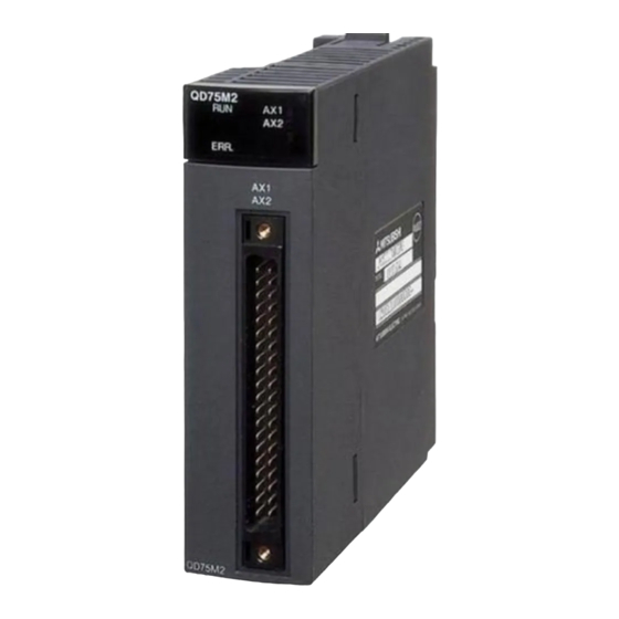
4 INSTALLATION, WIRING AND MAINTENANCE OF THE PRODUCT MELSEC-Q 4.1.2 Names of each part (1) The part names of the QD75 are shown below: For QD75M4 (1) RUN indicator LED, ERR indicator LED QD75M4 (2) Axis display LED QD75M4 (3) External device connector (40-pin connector) AX1: Axis 1 AX2: Axis 2... - Page 75 AX1 to AX4 are stopped or on OFF. standby. The symbols in the Display column indicate the following statuses: : Turns OFF. : Illuminates. : Flashes. The interface for each QD75 is shown below: QD75M1 QD75M2 QD75M4 QD75M1 QD75M2 QD75M4 QD75M4 QD75M1 QD75M2...
-
Page 76: Handling Precautions
4 INSTALLATION, WIRING AND MAINTENANCE OF THE PRODUCT MELSEC-Q 4.1.3 Handling precautions Handle the QD75 and cable while observing the following precautions. [1] Handling precautions CAUTION Use the PLC within the general specifications environment given in this manual. Using the PLC outside the general specification range environment could lead to electric shocks, fires, malfunctioning, product damage or deterioration. - Page 77 4 INSTALLATION, WIRING AND MAINTENANCE OF THE PRODUCT MELSEC-Q [2] Other precautions (1) Main body • The main body case is made of plastic. Take care not to drop or apply strong impacts onto the case. • Do not remove the QD75 PCB from the case. Failure to observe this could lead to faults.
-
Page 78: Installation
4 INSTALLATION, WIRING AND MAINTENANCE OF THE PRODUCT MELSEC-Q 4.2 Installation 4.2.1 Precautions for installation The precautions for installing the QD75 are given below. Refer to this section as well as "4.1.3 Handling precautions" when carrying out the work. [1] Precautions for SSCNET cable wiring If the duct is below the bottom of the module, leave sufficient clearance to eliminate effects on the SSCNET cable, limit the space height to 70 mm (2.76 inch) MIN. -
Page 79: Precautions For Installation
4 INSTALLATION, WIRING AND MAINTENANCE OF THE PRODUCT MELSEC-Q [2] Precautions for installation DANGER Always turn all phases of the power supply OFF externally before cleaning or tightening the screws. Failure to turn all phases OFF could lead to electric shocks. CAUTION Never disassemble or modify the module. -
Page 80: Wiring
4 INSTALLATION, WIRING AND MAINTENANCE OF THE PRODUCT MELSEC-Q 4.3 Wiring The precautions for wiring the QD75 are given below. Refer to this section as well as "4.1.3 Handling precautions" when carrying out the work. 4.3.1 Precautions for wiring DANGER Switch all phases of the external power supply off when installing or placing wiring. -
Page 81: Precautions For Wiring
4 INSTALLATION, WIRING AND MAINTENANCE OF THE PRODUCT MELSEC-Q [1] Precautions for wiring (1) Use separate cables for connecting to the QD75 and for the power cable that create surge and inductance. (2) The shielded cable for connecting QD75 can be secured in place. If the shielded cable is not secured, unevenness or movement of the shielded cable or careless pulling on it could result in damage to the QD75 or drive unit or shielded cable or defective cable connections could cause... - Page 82 4 INSTALLATION, WIRING AND MAINTENANCE OF THE PRODUCT MELSEC-Q [Processing example of shielded cables] Connections of FG wire and each shielded cable Remove the covering from all shielded cables and bind the appeared shield with a conductive tape. Coat the wire with insulaing tape.
- Page 83 (5) To make this product conform to the EMC directive and low voltage instruction, be sure to used of a AD75CK type cable clamp (manufactured by Mitsubishi Electric) for grounding connected to the control box and the shielded cable/ the SSCNET cable.
- Page 84 4 INSTALLATION, WIRING AND MAINTENANCE OF THE PRODUCT MELSEC-Q [Wiring examples using duct (incorrect example and corrected example)] Wiring duct Relay Relay Servo Servo Relay amplifier amplifier Control panel The servo amplifiers are placed Noise source near the noise source. (Power system, The connection cable between etc.)
-
Page 85: Confirming The Installation And Wiring
4 INSTALLATION, WIRING AND MAINTENANCE OF THE PRODUCT MELSEC-Q 4.4 Confirming the installation and wiring 4.4.1 Items to confirm when installation and wiring are completed Check the following points when completed with the QD75 installation and wiring. • Is the module correctly wired? ... "Connection confirmation" With "connection confirmation", the following three points are confirmed using GX Configurator-QP's connection confirmation function. -
Page 86: Maintenance
4 INSTALLATION, WIRING AND MAINTENANCE OF THE PRODUCT MELSEC-Q 4.5 Maintenance 4.5.1 Precautions for maintenance The precautions for servicing the QD75 are given below. Refer to this section as well as "4.1.3 Handling precautions" when carrying out the work. DANGER Always turn all phases of the power supply OFF externally before cleaning or tightening the screws. - Page 87 4 INSTALLATION, WIRING AND MAINTENANCE OF THE PRODUCT MELSEC-Q MEMO 4 - 16...
- Page 88 Chapter 5 Data Used for Positioning Control The parameters and data used to carry out positioning control with the QD75 are explained in this chapter. With the positioning system using the QD75, the various parameters and data explained in this chapter are used for control. The parameters and data include parameters set according to the device configuration, such as the system configuration, and parameters and data set according to each control.
-
Page 89: Types Of Data
5 DATA USED FOR POSITIONING CONTROL MELSEC-Q 5.1 Types of data 5.1.1 Parameters and data required for control The parameters and data required to carry out control with the QD75 include the "setting data", "monitor data" and "control data" shown below. Setting data (Data set beforehand according to the machine and application, and stored in the flash ROM.) Positioning... - Page 90 5 DATA USED FOR POSITIONING CONTROL MELSEC-Q The only valid data assigned to these parameters are the data read at the moment when a positioning or JOG operation is started. Once the operation has started, any modification to the data is ignored. Exceptionally, however, modifications to the following are valid even when they are made during a positioning operation: acceleration time 0 to 3, deceleration time 0 to 3, and external start command.
-
Page 91: Setting Items For Positioning Parameters
5 DATA USED FOR POSITIONING CONTROL MELSEC-Q 5.1.2 Setting items for positioning parameters The table below lists items set to the positioning parameters. Setting of positioning parameters is similarly done for individual axes for all controls achieved by the QD75. For details of controls, refer to Section 2. - Page 92 5 DATA USED FOR POSITIONING CONTROL MELSEC-Q Control Major positioning control Manual control Position control Other control Positioning parameter Pr.25 Acceleration time 1 – – – Pr.26 Acceleration time 2 – – – Pr.27 Acceleration time 3 – – – 12.7.7 Pr.28 Deceleration time 1...
-
Page 93: Setting Items For Opr Parameters
5 DATA USED FOR POSITIONING CONTROL MELSEC-Q 5.1.3 Setting items for OPR parameters When carrying out "OPR control", the "OPR parameters" must be set. The setting items for the "OPR parameters" are shown below. The "OPR parameters" are set commonly for each axis. Refer to "Chapter 8 OPR control"... -
Page 94: Setting Items For Servo Parameters
5 DATA USED FOR POSITIONING CONTROL MELSEC-Q 5.1.4 Setting items for servo parameters The servo parameters are used to control the servomotor and the data that is determined by the specification of the servo being used. The table below lists items set to the servo parameters. Servo amplifier MR-H-BN MR-H-BN4 MR-J2-B... - Page 95 5 DATA USED FOR POSITIONING CONTROL MELSEC-Q Servo amplifier MR-H-BN MR-H-BN4 MR-J2-B MR-J2S-B MR-J2-Jr MR-J2M-B Remark Servo parameters Pr.127 Monitor output 1 offset – Pr.128 Monitor output 2 offset – Pr.129 Pre-alarm data selection – – – – Pr.130 Zero speed Pr.131 Error excessive alarm level Pr.132 Optional function 5 Pr.133 Optional function 6...
-
Page 96: Setting Items For Positioning Data
5 DATA USED FOR POSITIONING CONTROL MELSEC-Q 5.1.5 Setting items for positioning data Positioning data must be set for carrying out any "major positioning control". The table below lists the items to be set for producing the positioning data. One to 600 positioning data items can be set for each axis. For details of the major positioning controls, refer to "Chapter 9 Major Positioning Control". - Page 97 5 DATA USED FOR POSITIONING CONTROL MELSEC-Q Checking the positioning data Da.1 Da.10 The items are checked at the following timings: (1) Startup of a positioning operation (2) Error check performed by GX Configurator-QP 5 - 10...
- Page 98 5 DATA USED FOR POSITIONING CONTROL MELSEC-Q MEMO 5 - 11...
-
Page 99: Setting Items For Block Start Data
5 DATA USED FOR POSITIONING CONTROL MELSEC-Q 5.1.6 Setting items for block start data The "block start data" must be set when carrying out "high-level positioning control". The setting items for the " block start data" are shown below. Up to 50 points of " block start data" can be set for each axis. Refer to "Chapter 10 High-level Positioning Control"... -
Page 100: Setting Items For Condition Data
5 DATA USED FOR POSITIONING CONTROL MELSEC-Q 5.1.7 Setting items for condition data When carrying out "high-level positioning control" or using the JUMP instruction in the "major positioning control", the "condition data" must be set as required. The setting items for the "condition data" are shown below. Up to 10 "condition data"... -
Page 101: Types And Roles Of Monitor Data
5 DATA USED FOR POSITIONING CONTROL MELSEC-Q 5.1.8 Types and roles of monitor data The monitor data area in the buffer memory stores data relating to the operating state of the positioning system, which are monitored as required while the positioning system is operating. - Page 102 5 DATA USED FOR POSITIONING CONTROL MELSEC-Q [2] Monitoring the axis operation state Monitoring the position Monitor details Corresponding item • Md.21 Machine feed value Monitor the current machine feed value • Md.20 Current feed value Monitor the current "current feed value" •...
- Page 103 5 DATA USED FOR POSITIONING CONTROL MELSEC-Q Monitoring the state Monitor details Corresponding item • Md.26 Axis operation status Monitor the axis operation state • Md.23 Axis error No. Monitor the latest error code that occurred with the axis • Md.24 Axis warning No.
- Page 104 5 DATA USED FOR POSITIONING CONTROL MELSEC-Q MEMO 5 - 17...
-
Page 105: Types And Roles Of Control Data
5 DATA USED FOR POSITIONING CONTROL MELSEC-Q 5.1.9 Types and roles of control data Operation of the positioning system is achieved through the execution of necessary controls. (Data required for controls are given through the default values when the power is switched ON, which can be modified as required by the sequence program.) Controls are performed over system data or machine operation. - Page 106 5 DATA USED FOR POSITIONING CONTROL MELSEC-Q [2] Controlling the operation Controlling the operation Control details Corresponding item • Cd.3 Positioning start No. Set which positioning to execute (start No.). • Cd.5 Md.23 Md.24 Clear (reset) the axis error ( ) and warning ( Axis error reset •...
- Page 107 5 DATA USED FOR POSITIONING CONTROL MELSEC-Q Making settings related to operation Control details Corresponding item • Cd.7 M code OFF request Turn M code ON signal OFF. • Cd.9 New current value Set new value when changing current value. •...
- Page 108 5 DATA USED FOR POSITIONING CONTROL MELSEC-Q MEMO 5 - 21...
-
Page 109: List Of Parameters
5 DATA USED FOR POSITIONING CONTROL MELSEC-Q 5.2 List of parameters 5.2.1 Basic parameters 1 Setting value buffer memory Setting value, setting range Default address Item value Value set with sequence Value set with peripheral device Axis 1 Axis 2 Axis 3 Axis 4 program 0 : mm 1 : inch... - Page 110 Pr.2 No. of pulses per rotation (AP) Set the number of pulses required for a complete rotation of the motor shaft. If you are using the Mitsubishi servo amplifier MR-H-BN/MR-J2-B/MR-J2S-B/MR- J2-03B5 set the value given as the "resolution per servomotor rotation" in the speed/position detector specifications.
- Page 111 5 DATA USED FOR POSITIONING CONTROL MELSEC-Q However, the maximum value that can be set for this "movement amount per rotation (AL)" parameter is 20000000.0 µ m (20m). Set the "movement amount per rotation (AL)" as shown below so that the "movement amount per rotation (AL)" does not exceed this maximum value.
- Page 112 5 DATA USED FOR POSITIONING CONTROL MELSEC-Q MEMO 5 - 25...
-
Page 113: Basic Parameters 2
5 DATA USED FOR POSITIONING CONTROL MELSEC-Q 5.2.2 Basic parameters 2 Setting value buffer memory Setting value, setting range Default address Item value Value set with sequence Value set with peripheral device Axis 1 Axis 2 Axis 3 Axis 4 program Pr.1 The setting range differs depending on the "... - Page 114 5 DATA USED FOR POSITIONING CONTROL MELSEC-Q [Table 1] Pr.1 setting value Value set with peripheral device (unit) Value set with sequence program (unit) 1 to 2000000000 (×10 mm/min) 0 : mm 0.01 to 20000000.00 (mm/min) 1 : inch 0.001 to 2000000.000 (inch/min) 1 to 2000000000 (×10 inch/min) 1 to 2000000000 (×10...
-
Page 115: Detailed Parameters 1
5 DATA USED FOR POSITIONING CONTROL MELSEC-Q 5.2.3 Detailed parameters 1 Setting value buffer memory Setting value, setting range address Item Default value Value set with Value set with peripheral device Axis 1 Axis 2 Axis 3 Axis 4 sequence program Pr.1 The setting value range differs according to the Unit... - Page 116 5 DATA USED FOR POSITIONING CONTROL MELSEC-Q Pr.11 Backlash compensation amount) Pr.2 No. of pulses per rotation) 0 ≤ ( = A) ≤ 65535 (PLS) ….(1) Pr.3 Movement amount per pulse) Pr.2 An error (error code: 920) occurs when " No.
- Page 117 5 DATA USED FOR POSITIONING CONTROL MELSEC-Q 1) Generally, the OP is set at the lower limit or upper limit of the stroke limit. 2) By setting the upper limit value or lower limit value of the software stroke limit, overrun can be prevented in the software.
- Page 118 5 DATA USED FOR POSITIONING CONTROL MELSEC-Q Pr.17 Torque limit setting value Set the maximum value of the torque generated by the servomotor as a percentage between 1 and 500%. The torque limit function limits the torque generated by the servomotor within the set range.
- Page 119 5 DATA USED FOR POSITIONING CONTROL MELSEC-Q Setting value buffer memory Setting value, setting range Default address Item value Value set with sequence Value set with peripheral device Axis 1 Axis 2 Axis 3 Axis 4 program 0 : Standard speed switching mode Pr.19 1 : Front-loading speed switching Speed switching mode...
- Page 120 5 DATA USED FOR POSITIONING CONTROL MELSEC-Q Pr.19 Speed switching mode Set whether to switch the speed switching mode with the standard switching or front-loading switching mode. 0 : Standard switching....Switch the speed when executing the next positioning data. 1 : Front-loading switching ..
- Page 121 5 DATA USED FOR POSITIONING CONTROL MELSEC-Q Pr.21 Current feed value during speed control Md.20 Specify whether you wish to enable or disable the update of " Current feed value" while operations are performed under the speed control (including the speed-position and position-speed switching control).
- Page 122 5 DATA USED FOR POSITIONING CONTROL MELSEC-Q MEMO 5 - 35...
-
Page 123: Detailed Parameters 2
5 DATA USED FOR POSITIONING CONTROL MELSEC-Q 5.2.4 Detailed parameters 2 Setting value buffer memory Setting value, setting range Default address Item value Value set with sequence Value set with peripheral device Axis 1 Axis 2 Axis 3 Axis 4 program Pr.25 Acceleration time 1... - Page 124 5 DATA USED FOR POSITIONING CONTROL MELSEC-Q [Table 1] Value set with peripheral device Value set with sequence program Pr.1 setting value (unit) (unit) 1 to 2000000000 ( × 10 0 : mm 0.01 to 20000000.00 (mm/min) mm/min) 1 to 2000000000 ( × 10 1 : inch 0.001 to 2000000.000 (inch/min) inch/min)
- Page 125 5 DATA USED FOR POSITIONING CONTROL MELSEC-Q Setting value buffer memory Setting value, setting range Default address Item value Value set with sequence Value set with peripheral device Axis 1 Axis 2 Axis 3 Axis 4 program 0 : Automatic trapezoid Pr.34 acceleration/deceleration process Acceleration/deceleration...
- Page 126 5 DATA USED FOR POSITIONING CONTROL MELSEC-Q Pr.35 S-pattern ratio Set the S-pattern ratio (1 to 100%) for carrying out the S-pattern acceleration/deceleration process. The S-pattern ratio indicates where to draw the acceleration/deceleration curve using the Sin curve as shown below. (Example) Positioning speed...
- Page 127 5 DATA USED FOR POSITIONING CONTROL MELSEC-Q Pr.36 Sudden stop deceleration time Pr.8 Set the time to reach speed 0 from " Speed limit value" during the sudden stop. The illustration below shows the relationships with other parameters. 1) Positioning start 2) Sudden stop cause occurrence 3) Positioning stop When positioning is started,...
- Page 128 5 DATA USED FOR POSITIONING CONTROL MELSEC-Q Pr.37 Stop group 1 sudden stop selection Pr.39 Stop group 3 sudden stop selection Set the method to stop when the stop causes in the following stop groups occur. • Stop group 1 ....Stop with hardware stroke limit •...
- Page 129 5 DATA USED FOR POSITIONING CONTROL MELSEC-Q Setting value buffer memory Setting value, setting range Default address Item value Value set with sequence Value set with peripheral device Axis 1 Axis 2 Axis 3 Axis 4 program 0 to 65535 (ms) 0 to 32767 : Pr.40 Set as a decimal...
- Page 130 5 DATA USED FOR POSITIONING CONTROL MELSEC-Q [Table 1] Value set with peripheral device Value set with sequence program Pr.1 setting value (unit) (unit) 0 to 100000 ( × 10 µ m) 0 to 10000.0 ( µ m) 0 : mm 0 to 100000 ( ×...
- Page 131 5 DATA USED FOR POSITIONING CONTROL MELSEC-Q Pr.42 External command function selection Select a command with which the external command signal should be associated. 0: External positioning start The external command signal input is used to start a positioning operation. 1: External speed change request The external command signal input is used to change the speed in the current positioning operation.
- Page 132 5 DATA USED FOR POSITIONING CONTROL MELSEC-Q 2) When the difference between the last command position of the QD75 at the time the servo stop signal turned ON and the present value at the time the servo stop signal turned OFF is greater than the value set in the buffer memory for the restart allowable range setting, the positioning operation is judged as on-standby and cannot be restarted.
- Page 133 5 DATA USED FOR POSITIONING CONTROL MELSEC-Q (3) Precautionary notes (a) The setting for the "restart allowable range when servo OFF changes to ON" is validated when the PLC READY signal (Y0) rises (OFF to ON). After setting the "restart allowable range when servo OFF changes to ON", the PLC READY signal (Y0) rises (OFF to ON).
- Page 134 5 DATA USED FOR POSITIONING CONTROL MELSEC-Q MEMO 5 - 47...
-
Page 135: Opr Basic Parameters
5 DATA USED FOR POSITIONING CONTROL MELSEC-Q 5.2.5 OPR basic parameters Setting value buffer memory Setting value, setting range Default address Item value Value set with sequence Value set with peripheral device Axis 1 Axis 2 Axis 3 Axis 4 program 0 : Near-point dog method Pr.43... - Page 136 5 DATA USED FOR POSITIONING CONTROL MELSEC-Q 4 : Count method 1) (1) Start OPR. Pr.46 (Start movement at the OPR speed in Pr.50 OPR speed Pr.46 Pr.44 Setting for the movement OPR direction.) amount after near-poing dog ON Pr.47 Creep speed (2) Detect the near-point dog ON, and start deceleration.
- Page 137 5 DATA USED FOR POSITIONING CONTROL MELSEC-Q Setting value buffer memory Setting value, setting range Default address Item value Value set with sequence Value set with peripheral device Axis 1 Axis 2 Axis 3 Axis 4 program 0 : Positive direction (address Pr.44 increment direction) 1 : Negative direction (address...
- Page 138 5 DATA USED FOR POSITIONING CONTROL MELSEC-Q [Table 1] Value set with peripheral device Value set with sequence program Pr.1 setting value (unit) (unit) -2147483648 to 2147483647 ( × 10 µ m) -214748364.8 to 214748364.7 ( µ m) 0 : mm -2147483648 to 2147483647 ( ×...
- Page 139 5 DATA USED FOR POSITIONING CONTROL MELSEC-Q Setting value buffer memory Setting value, setting range Default address Item value Value set with sequence Value set with peripheral device Axis 1 Axis 2 Axis 3 Axis 4 program Pr.1 The setting value range differs depending on the Unit setting.
- Page 140 5 DATA USED FOR POSITIONING CONTROL MELSEC-Q [Table 1] Value set with peripheral device Value set with sequence program Pr.1 setting value (unit) (unit) 1 to 2000000000 ( × 10 0 : mm 0.01 to 20000000.00 (mm/min) mm/min) 1 to 2000000000 ( × 10 1 : inch 0.001 to 2000000.000 (inch/min) inch/min)
-
Page 141: Opr Detailed Parameters
5 DATA USED FOR POSITIONING CONTROL MELSEC-Q 5.2.6 OPR detailed parameters Setting value buffer memory Setting value, setting range Default address Item value Value set with sequence Value set with peripheral device Axis 1 Axis 2 Axis 3 Axis 4 program The setting value range differs depending on the Pr.1... - Page 142 5 DATA USED FOR POSITIONING CONTROL MELSEC-Q [Table 1] Value set with peripheral device Value set with sequence program Pr.1 setting value (unit) (unit) 0 to 2147483647 ( × 10 µ m) 0 to 214748364.7 ( µ m) 0 : mm 0 to 2147483647 ( ×...
- Page 143 5 DATA USED FOR POSITIONING CONTROL MELSEC-Q Setting value buffer memory Setting value, setting range Default address Item value Value set with peripheral Value set with sequence program Axis 1 Axis 2 Axis 3 Axis 4 device Pr.1 The setting value range differs depending on the Unit setting.
- Page 144 5 DATA USED FOR POSITIONING CONTROL MELSEC-Q [Table 1] Value set with peripheral device Value set with sequence program Pr.1 setting value (unit) (unit) -2147483648 to 2147483647 ( × 10 µ m) -214748364.8 to 214748364.7 ( µ m) 0 : mm -2147483648 to 2147483647 ( ×...
-
Page 145: Servo Basic Parameters
5 DATA USED FOR POSITIONING CONTROL MELSEC-Q 5.2.7 Servo basic parameters The Pr.101 correspond with "parameter No.1 of the servo amplifier". The following parameter correspond with "servo amplifier parameters No." in the same way. Item Setting details Setting value 1 0: MR-H-BN Used to select the servo amplifier series, which is 1: MR-H-BN4-B... - Page 146 5 DATA USED FOR POSITIONING CONTROL MELSEC-Q Setting Value, setting range Setting value buffer memory address Value set with peripheral device Default Servo amplifier setting invalid ( : Invalid, : Valid) Value set with sequence program value Axis 1 Axis 2 Axis 3 Axis 4 H-BN H-BN4 J2-B...
- Page 147 5 DATA USED FOR POSITIONING CONTROL MELSEC-Q Item Setting details Setting value 1 00: HA-SH Standard 01: HA-LH Low inertia 02: HA-UH Flat 03: HA-FH/HA-FF 05: HA-MH Used to select the motor type. 07: HC-SF Use it "0080 : Automatic setting" usually. 08: HC-RF POINT Pr.103...
- Page 148 5 DATA USED FOR POSITIONING CONTROL MELSEC-Q Setting Value, setting range Setting value buffer memory address Value set with peripheral device Default Servo amplifier setting invalid ( : Invalid, : Valid) value Value set with sequence program Axis 1 Axis 2 Axis 3 Axis 4 H-BN H-BN4 J2-B...
- Page 149 5 DATA USED FOR POSITIONING CONTROL MELSEC-Q Item Setting details Setting value 1 0: Auto tuning selected for use of interpolation axis control, etc. in position 1: Auto tuning for ordinary operation. Pr.108 Auto tuning Used to select the auto tuning. 2: Invalid (No auto tuning) 0: Interpolation mode 1: Auto tuning mode 1...
- Page 150 5 DATA USED FOR POSITIONING CONTROL MELSEC-Q Setting Value, setting range Setting value buffer memory address Value set with peripheral device Default Servo amplifier setting invalid ( : Invalid, : Valid) value Value set with sequence program Axis 1 Axis 2 Axis 3 Axis 4 H-BN H-BN4 J2-B...
-
Page 151: Servo Adjustment Parameters
5 DATA USED FOR POSITIONING CONTROL MELSEC-Q 5.2.8 Servo adjustment parameters Item Setting details Setting value 1 Used to set the ratio of the load inertia to the inertia moment of the servomotor. When auto tuning is selected, the result of auto tuning 0 to 100.0[times] is automatically used. - Page 152 5 DATA USED FOR POSITIONING CONTROL MELSEC-Q Setting Value, setting range Setting value buffer memory address Value set with peripheral device Default Servo amplifier setting invalid ( : Invalid, : Valid) value Value set with sequence program Axis 1 Axis 2 Axis 3 Axis 4 H-BN H-BN4 J2-B...
- Page 153 5 DATA USED FOR POSITIONING CONTROL MELSEC-Q Item Setting details Setting value 1 00: Not used 01: 1125[Hz] 02: 563[Hz] 03: 375[Hz] 04: 282[Hz] 05: 225[Hz] 06: 188[Hz] 07: 161[Hz] 00: Invalid 08: 141[Hz] 01: 1125[Hz] 09: 125[Hz] 02: 563[Hz] 10: 113[Hz] 03: 375[Hz] 11: 102[Hz]...
- Page 154 5 DATA USED FOR POSITIONING CONTROL MELSEC-Q Setting Value, setting range Setting value buffer memory address Value set with peripheral device Default Servo amplifier setting invalid ( : Invalid, : Valid) value Value set with sequence program Axis 1 Axis 2 Axis 3 Axis 4 H-BN H-BN4 J2-B...
- Page 155 5 DATA USED FOR POSITIONING CONTROL MELSEC-Q Item Setting details Setting value 1 Used to set the droop pulse range in which the in- position signal will be output to the servo system controller. Pr.120 In-position range 0 to 50000[PLS] POINT Only MR-J2S-B sets up Pr.106 F eed back pulse in the feed back pulse unit.
- Page 156 5 DATA USED FOR POSITIONING CONTROL MELSEC-Q Setting Value, setting range Setting value buffer memory address Value set with peripheral device Default Servo amplifier setting invalid ( : Invalid, : Valid) value Value set with sequence program Axis 1 Axis 2 Axis 3 Axis 4 H-BN H-BN4 J2-B...
- Page 157 5 DATA USED FOR POSITIONING CONTROL MELSEC-Q Item Setting details Setting value 1 0: Servo motor speed ( 8V/max. speed) 1: Generated torque ( 8V/max. torque) 2: Motor speed ( + 8V/max. speed) 3: Generated torque ( + 8V/max. torque) 4: Current command ( 8V/max.
- Page 158 5 DATA USED FOR POSITIONING CONTROL MELSEC-Q Setting Value, setting range Setting value buffer memory address Value set with peripheral device Default Servo amplifier setting invalid ( : Invalid, : Valid) value Value set with sequence program Axis 1 Axis 2 Axis 3 Axis 4 H-BN H-BN4 J2-B...
- Page 159 5 DATA USED FOR POSITIONING CONTROL MELSEC-Q Item Setting details Setting value 1 0: Invalid Slight vibration 1: Valid(Gain adjustment suppression control mode: Manual mode Pr.108 selection is set up "2" )) Motor-less operation 0: Invalid selection 1: Valid Pr.124 Used to set the optional function 2.
- Page 160 5 DATA USED FOR POSITIONING CONTROL MELSEC-Q Setting Value, setting range Setting value buffer memory address Value set with peripheral device Default Servo amplifier setting invalid ( : Invalid, : Valid) value Value set with sequence program Axis 1 Axis 2 Axis 3 Axis 4 H-BN H-BN4 J2-B...
-
Page 161: Servo Expansion Parameters
5 DATA USED FOR POSITIONING CONTROL MELSEC-Q 5.2.9 Servo expansion parameters Item Setting details Setting value 1 -9999 to 9999 Monitor output 1 offset Pr.127 Used to set the offset voltage for monitor output 1. (Analog monitor 1 offset) -999 to 999 -9999 to 9999 Monitor output 2 offset Pr.128... - Page 162 5 DATA USED FOR POSITIONING CONTROL MELSEC-Q Setting Value, setting range Setting value buffer memory address Value set with peripheral device Default Servo amplifier setting invalid ( : Invalid, : Valid) value Value set with sequence program Axis 1 Axis 2 Axis 3 Axis 4 H-BN H-BN4 J2-B...
- Page 163 5 DATA USED FOR POSITIONING CONTROL MELSEC-Q Item Setting details Setting value 1 Serial communication 0: 9600[bps] 2: 38400[bps] baud rate selection 1: 19200[bps] 3: 57600[bps] A communication baud rate selection and Serial communication 0: Invalid communication answer delay time and encoder output response delay time 1: Valid (It answer after delay selection...
- Page 164 5 DATA USED FOR POSITIONING CONTROL MELSEC-Q Setting Value, setting range Setting value buffer memory address Value set with peripheral device Default Servo amplifier setting invalid ( : Invalid, : Valid) value Value set with sequence program Axis 1 Axis 2 Axis 3 Axis 4 H-BN H-BN4 J2-B...
-
Page 165: Servo Expansion Parameters 2
5 DATA USED FOR POSITIONING CONTROL MELSEC-Q 5.2.10 Servo expansion parameters 2 Item Setting details Setting value 1 Position gain 2 shift value 0: 1.0[times] Pr.143 Used to set each of the gain shift value which the 1: 0.75[times] Speed gain 2 shift slight vibration suppression control selected. - Page 166 5 DATA USED FOR POSITIONING CONTROL MELSEC-Q Setting Value, setting range Setting value buffer memory address Value set with peripheral device Default Servo amplifier setting invalid ( : Invalid, : Valid) value Value set with sequence program Axis 1 Axis 2 Axis 3 Axis 4 H-BN H-BN4 J2-B...
- Page 167 5 DATA USED FOR POSITIONING CONTROL MELSEC-Q Item Setting details Setting value 1 Speed integral compensation Used to set the ratio of changing the speed integral changing ratio Pr.155 compensation when gain changing is valid. Made 50 to 1000[%] (VEL. INTGRL. COMPS. valid when auto tuning is invalid.
- Page 168 5 DATA USED FOR POSITIONING CONTROL MELSEC-Q Setting Value, setting range Setting value buffer memory address Value set with peripheral device Default Servo amplifier setting invalid ( : Invalid, : Valid) Value set with sequence program value Axis 1 Axis 2 Axis 3 Axis 4 H-BN H-BN4 J2-B...
-
Page 169: List Of Positioning Data
5 DATA USED FOR POSITIONING CONTROL MELSEC-Q 5.3 List of positioning data Da.1 Da.10 Before explaining the positioning data setting items , the configuration of the positioning data will be shown below. The positioning data stored in the QD75 buffer memory has the following type of configuration. - Page 170 5 DATA USED FOR POSITIONING CONTROL MELSEC-Q ˆ Ê ’ u Œ ˆ ‚ ß Ž ¯ • Ê Ž q ˆ Ê ’ u Œ ˆ ‚ ß Ž ¯ • Ê Ž q 19990 19980 Da.1@ ` @ Da.4 Da.1@ ` @ Da.4 Positioning data No.
- Page 171 5 DATA USED FOR POSITIONING CONTROL MELSEC-Q Setting value buffer memory Default Setting value Item address value Value set with peripheral device Value set with sequence program Axis 1 Axis 2 Axis 3 Axis 4 00: Positioning complete Da.1 Operation pattern Operation 01: Continuous positioning control pattern...
- Page 172 5 DATA USED FOR POSITIONING CONTROL MELSEC-Q Da.1 Operation pattern The operation pattern designates whether positioning of a certain data No. is to be ended with just that data, or whether the positioning for the next data No. is to be carried out in succession.
- Page 173 5 DATA USED FOR POSITIONING CONTROL MELSEC-Q Da.4 Deceleration time No. Set which of "deceleration time 0 to 3" to use for the deceleration time during positioning. Pr.10 0 : Use the value set in Deceleration time 0. Pr.28 1 : Use the value set in Deceleration time 1.
- Page 174 5 DATA USED FOR POSITIONING CONTROL MELSEC-Q (2) Incremental (INC) system, fixed-feed 1, fixed-feed 2, fixed-feed 3, fixed-feed 4 • The setting value (movement amount) for the INC system is set as a movement amount with sign. When movement amount is positive: Moves in the positive direction (address increment direction) When movement amount is negative: Moves in the negative direction (address decrement direction)
- Page 175 5 DATA USED FOR POSITIONING CONTROL MELSEC-Q (3) Speed-position switching control • INC mode: Set the amount of movement after the switching from speed control to position control. • ABS mode: Set the absolute address which will be the target value after speed control is switched to position control.
- Page 176 5 DATA USED FOR POSITIONING CONTROL MELSEC-Q Pr.1 When " Unit Setting" is "PLS" The table below lists the control systems that require the setting of the positioning address or movement amount and the associated setting ranges. (With any control system excluded from the table below, neither the positioning address nor the movement amount needs to be set.) Value set with peripheral device Value set with sequence program...
- Page 177 5 DATA USED FOR POSITIONING CONTROL MELSEC-Q Pr.1 When " Unit Setting" is "inch" The table below lists the control systems that require the setting of the positioning address or movement amount and the associated setting ranges. (With any control system excluded from the table below, neither the positioning address nor the movement amount needs to be set.) Value set with sequence program Value set with peripheral device...
- Page 178 5 DATA USED FOR POSITIONING CONTROL MELSEC-Q MEMO 5 - 91...
- Page 179 5 DATA USED FOR POSITIONING CONTROL MELSEC-Q Setting value buffer memory Setting value, setting range Default address Item value Value set with sequence Value set with peripheral device Axis 1 Axis 2 Axis 3 Axis 4 program Da.2 The setting value range differs according to the Control system.
- Page 180 5 DATA USED FOR POSITIONING CONTROL MELSEC-Q [Table 1] Pr.1 When " Unit Setting" is "mm" The table below lists the control systems that require the setting of the arc address and shows the setting range. (With any control system excluded from the table below, the arc address does not need to be set.) Value set with sequence program Value set with peripheral device...
- Page 181 5 DATA USED FOR POSITIONING CONTROL MELSEC-Q Setting value buffer memory Setting value, setting range Default address Item value Value set with sequence Value set with peripheral device Axis 1 Axis 2 Axis 3 Axis 4 program Pr.1 The setting value range differs depending on the Unit setting.
- Page 182 5 DATA USED FOR POSITIONING CONTROL MELSEC-Q Da.10 M code (or condition data No./No. of LOOP to LEND repetitions) Set an "M code", a "condition data No. ", or the "number of LOOP to LEND Da.2 repetitions" depending on how the " Control system"...
- Page 183 5 DATA USED FOR POSITIONING CONTROL MELSEC-Q Da.9 Dwell time/JUMP designation positioning data No. Da.2 Set the "dwell time" or "positioning data No." corresponding to the " Control system". • Da.2 When a method other than "JUMP instruction " is set for " Control system"...
- Page 184 5 DATA USED FOR POSITIONING CONTROL MELSEC-Q MEMO 5 - 97...
-
Page 185: List Of Block Start Data
5 DATA USED FOR POSITIONING CONTROL MELSEC-Q 5.4 List of block start data The illustrations below show the organization of the block start data stored in the QD75 Da.11 Da.14 buffer memory. The block start data setting items are explained in the pages that follow. - Page 186 5 DATA USED FOR POSITIONING CONTROL MELSEC-Q 50th point Buffer memory Setting item address 2nd point Buffer memory 1st point Setting item address 28049 Buffer memory Setting item address œ ˆ Ê ’ u Œ ˆ ‚ ß Ž n “ ® ƒ f [ ƒ ^ 28001 28000 Da.12 Start data No.
- Page 187 5 DATA USED FOR POSITIONING CONTROL MELSEC-Q REMARK To perform an high-level positioning control using block start data, set a number Cd.3 between 7000 and 7004 to the " Positioning start No." and use the Cd.4 " Positioning starting point No." to specify a point number between 1 and 50, a position counted from the beginning of the block.
- Page 188 5 DATA USED FOR POSITIONING CONTROL MELSEC-Q Setting value buffer memory Setting value Default address Item value Value set with peripheral Value set with sequence program Axis 1 Axis 2 Axis 3 Axis 4 device 0 : End Da.11 Shape 0 0 0 1 : Continue 0000...
- Page 189 5 DATA USED FOR POSITIONING CONTROL MELSEC-Q Da.11 Shape Set whether to carry out only the local "block start data" and then end control, or to execute the "block start data" set in the next point. Setting value Setting details 0 : End Execute the designated point's "block start data", and then complete the control.
- Page 190 5 DATA USED FOR POSITIONING CONTROL MELSEC-Q MEMO 5 - 103...
-
Page 191: List Of Condition Data
5 DATA USED FOR POSITIONING CONTROL MELSEC-Q 5.5 List of condition data The illustrations below show the organization of the condition data stored in the QD75 Da.15 Da.19 buffer memory. The condition data setting items are explained in the pages that follow. 10th point Up to 10 block start data points can be set (stored) Buffer memory... - Page 192 5 DATA USED FOR POSITIONING CONTROL MELSEC-Q 10th point Buffer memory Setting item address 2nd point Buffer memory 1st point Setting item address 28190 Buffer memory Setting item address 28110 28191 28192 28100 28193 Da.16 Condition Da.15 Condition 28194 operator target 28111 28195...
- Page 193 5 DATA USED FOR POSITIONING CONTROL MELSEC-Q REMARK To perform an high-level positioning control using block start data, set a number Cd.3 between 7000 and 7004 to the " Positioning start No." and use the Cd.4 " Positioning starting point No." to specify a point number between 1 and 50, a position counted from the beginning of the block.
- Page 194 5 DATA USED FOR POSITIONING CONTROL MELSEC-Q Setting value buffer memory Default Setting value Item address value Value set with peripheral device Value set with sequence program Axis 1 Axis 2 Axis 3 Axis 4 01 : Device X 02 : Device Y Da.15 Condition target 03 : Buffer memory (1-word)
- Page 195 5 DATA USED FOR POSITIONING CONTROL MELSEC-Q Da.15 Condition target Set the condition target as required for each control. Setting value Setting details : Device X Set the input/output signal ON/OFF as the conditions. : Device Y : Buffer memory (1-word) Set the value stored in the buffer memory as the condition.
- Page 196 5 DATA USED FOR POSITIONING CONTROL MELSEC-Q Da.18 Parameter 1 Da.16 Set the parameters as required for the " Condition operator". Da.16 Setting value Setting details Condition operator : ∗∗=P1 : ∗∗ ≠ P1 The value of P1 should be equal to or smaller than the value of : ∗∗≤P1 P2.
-
Page 197: List Of Monitor Data
5 DATA USED FOR POSITIONING CONTROL MELSEC-Q 5.6 List of monitor data 5.6.1 System monitor data Storage item Storage details Whether the mode is the test mode from the peripheral device or not is stored. • Md.1 In test mode flag When not in test mode : OFF •... - Page 198 5 DATA USED FOR POSITIONING CONTROL MELSEC-Q Storage buffer memory address Reading the monitor value Default value (common for axis 1 to axis 4) Monitoring is carried out with a decimal. Monitor Storage value 1200 value 0: Not in test mode 1: In test mode (Unless noted in particular, the monitor value is saved as binary data.) 5 - 111...
- Page 199 5 DATA USED FOR POSITIONING CONTROL MELSEC-Q Storage item Storage details Reading the monitor value [Storage details] This area stores the start information (restart flag, start origin, and start axis): • Restart flag: Indicates whether the operation has or has not been halted and restarted.
- Page 200 5 DATA USED FOR POSITIONING CONTROL MELSEC-Q Default value Storage buffer memory address (common to axes 1 to 4) Md.8 1292 Pointer 0000 Indicates a pointer No. that is next to the Pointer No. assigned to the latest of the existing starting history records. Pointer No.
- Page 201 5 DATA USED FOR POSITIONING CONTROL MELSEC-Q Storage item Storage details Reading the monitor value [Storage details] This area stores the following results of the error judgment performed upon starting: • BUSY start warning flag • Error flag • Error No. [Reading the monitor value] Monitoring is carried out with a hexadecimal display.
- Page 202 5 DATA USED FOR POSITIONING CONTROL MELSEC-Q Default value Storage buffer memory address (common to axes 1 to 4) Md.8 1292 Start history pointer Indicates a pointer No. that is next to the Pointer No. assigned to the latest of the existing starting history records. Pointer No.
- Page 203 5 DATA USED FOR POSITIONING CONTROL MELSEC-Q Storage item Storage details Reading the monitor value Monitoring is carried out with a decimal display. Md.9 Stores a number (Axis No.) Monitor Storage value Axis in which that indicates the axis that value 1: Axis 1 2: Axis 2...
- Page 204 5 DATA USED FOR POSITIONING CONTROL MELSEC-Q Default value Storage buffer memory address (common to axes 1 to 4) Md.13 1357 Error history pointer Indicates a pointer No. that is next to the Pointer No. assigned to the latest of the existing error history records. Pointer No.
- Page 205 5 DATA USED FOR POSITIONING CONTROL MELSEC-Q Storage item Storage details Reading the monitor value Monitoring is carried out with a decimal display. Md.14 Stores a number (Axis No.) Monitor Storage value Axis in which that indicates the axis that value 1: Axis 1 the warning...
- Page 206 5 DATA USED FOR POSITIONING CONTROL MELSEC-Q Default value Storage buffer memory address (common to axes 1 to 4) Md.18 1422 Warning history pointer Indicates a pointer No. that is next to the Pointer No. assigned to the latest of the existing warning history records. Pointer No.
-
Page 207: Axis Monitor Data
5 DATA USED FOR POSITIONING CONTROL MELSEC-Q 5.6.2 Axis monitor data Storage item Storage details The currently commanded address is stored. (Different from the actual motor position during operation) The current position address is stored. If "degree" is selected as the unit, the addresses will have a ring structure for values Md.20 between 0 and 359.9999 degrees. - Page 208 5 DATA USED FOR POSITIONING CONTROL MELSEC-Q Storage buffer Default memory address Reading the monitor value value Axis 1 Axis 2 Axis 3 Axis 4 Monitoring is carried out with a hexadecimal. 1100 1000 0000 Low-order buffer memory Example) 800 1001 1101 Monitor...
- Page 209 5 DATA USED FOR POSITIONING CONTROL MELSEC-Q Storage item Storage details Whenever an axis warning is reported, a related warning code is stored. • This area stores the latest warning code always. (Whenever an axis warning is reported, a new warning code replaces the stored warning code.) Md.24 Axis warning No.
- Page 210 5 DATA USED FOR POSITIONING CONTROL MELSEC-Q Storage buffer Default memory address Reading the monitor value value Axis 1 Axis 2 Axis 3 Axis 4 Monitoring is carried out with a decimal display. Monitor Warning No. 1007 1107 value For details of warning Nos. (warning codes), refer to "15.3 List of warnings".
- Page 211 5 DATA USED FOR POSITIONING CONTROL MELSEC-Q Storage item Storage details • The speed which is actually output as a command at that time in each axis is stored. (May be different from the actual motor speed) "0" is stored when the axis is at a stop. Update timing: 56.8ms Md.28 Axis feedrate...
- Page 212 5 DATA USED FOR POSITIONING CONTROL MELSEC-Q Storage buffer Default memory address Reading the monitor value value Axis 1 Axis 2 Axis 3 Axis 4 Monitoring is carried out with a hexadecimal. Low-order buffer memory Example) 812 Monitor value High-order buffer memory Example) 813 1012 1112 0000...
- Page 213 5 DATA USED FOR POSITIONING CONTROL MELSEC-Q Storage item Storage details This area stores the states (ON/OFF) of various flags. Information on the following flags is stored. In speed control flag: This signal that comes ON under the speed control can be used to judge whether the operation is performed under the speed control or position control.
- Page 214 5 DATA USED FOR POSITIONING CONTROL MELSEC-Q Storage buffer Default memory address Reading the monitor value value Axis 1 Axis 2 Axis 3 Axis 4 Monitoring is carried out with a hexadecimal display. Monitor value Buffer 0 0 0 0 0 0 0 0 0 0 0 0 0 0 0 0 memory Not used Not used...
- Page 215 5 DATA USED FOR POSITIONING CONTROL MELSEC-Q Storage item Storage details • During operation with positioning data : The actual target speed, considering the override and speed limit value, etc., is stored. "0" is stored when positioning is completed. • During interpolation : The composite speed or reference axis speed is stored in the reference...
- Page 216 5 DATA USED FOR POSITIONING CONTROL MELSEC-Q Storage buffer Default memory address Reading the monitor value value Axis 1 Axis 2 Axis 3 Axis 4 Monitoring is carried out with a hexadecimal display. Low-order buffer memory Example) 820 Monitor value High-order buffer memory Example) 821 1020 1120...
- Page 217 5 DATA USED FOR POSITIONING CONTROL MELSEC-Q Storage item Storage details • Md.36 Special start data instruction The " instruction code" used with special start and indicated by the start data pointer currently being executed is stored. code setting value The "...
- Page 218 5 DATA USED FOR POSITIONING CONTROL MELSEC-Q Storage buffer Default memory address Reading the monitor value value Axis 1 Axis 2 Axis 3 Axis 4 Monitoring is carried out with a decimal display. Monitor Storage value value 00: Block start (Normal start) 01: Condition start 1027 1127 02: Wait start...
- Page 219 5 DATA USED FOR POSITIONING CONTROL MELSEC-Q Storage item Storage details • This area stores the remaining number of repetitions during "repetitions" specific to special starting. Md.41 Special start repetition • The count is decremented by one (-1) at the loop end. counter •...
- Page 220 5 DATA USED FOR POSITIONING CONTROL MELSEC-Q Storage buffer Default memory address Reading the monitor value value Axis 1 Axis 2 Axis 3 Axis 4 Monitoring is carried out with a decimal display. Storage value 1032 1132 0 to 255 Monitor value Monitoring is carried out with a hexadecimal display.
- Page 221 5 DATA USED FOR POSITIONING CONTROL MELSEC-Q Storage item Storage details • This area stores the travel distance during the OPR travel to the zero point that was executed last time. OPR re-travel value For setting units Md.100 Example) mm (Buffer memory 0.1) µm •...
- Page 222 5 DATA USED FOR POSITIONING CONTROL MELSEC-Q Storage buffer Default memory address Reading the monitor value value Axis 1 Axis 2 Axis 3 Axis 4 Monitoring is carried out with a decimal display. Low-order buffer memory Example) 800 1048 1148 Monitor 1049 1149...
- Page 223 5 DATA USED FOR POSITIONING CONTROL MELSEC-Q Storage item Storage details Parameter error (No.1 to 15) Parameter error (No.16 to 31) • Parameter error (No.32 to 47) When a servo parameter error occurs, the Parameter error No. bit that corresponds to the parameter Md.107 Parameter error (No.48 to 63) number affected by the error comes ON.
- Page 224 5 DATA USED FOR POSITIONING CONTROL MELSEC-Q Storage buffer Default memory address Reading the monitor value value Axis 1 Axis 2 Axis 3 Axis 4 1070 1170 1071 1171 1072 1172 Monitoring is carried out with a decimal display. 1073 1173 1074 1174 1075 1175 1076 1176...
-
Page 225: List Of Control Data
5 DATA USED FOR POSITIONING CONTROL MELSEC-Q 5.7 List of control data 5.7.1 System control data Setting item Setting details • Requests writing of data (parameters, positioning data, and block start data) from the buffer memory to the flash ROM. POINT (1) Do not turn the power OFF or reset the PLC CPU while writing to the flash ROM. - Page 226 5 DATA USED FOR POSITIONING CONTROL MELSEC-Q Storage buffer memory address Setting value Default value (common to axes 1 to 4) Set with a decimal. Setting value 1900 Flash ROM write request 1: Requests write access to flash ROM. The QD75 resets the value to "0" automatically when the write access completes. (This indicates the completion of write operation.) Set with a decimal.
-
Page 227: Axis Control Data
5 DATA USED FOR POSITIONING CONTROL MELSEC-Q 5.7.2 Axis control data Setting item Setting details • Set the positioning start No. Cd.3 Positioning start No. (Only 1 to 600 for the Pre-reading start function. For details, refer to "Section 12.7.8 Pre-reading start function".) •... - Page 228 5 DATA USED FOR POSITIONING CONTROL MELSEC-Q Storage buffer Default memory address Setting value value Axis 1 Axis 2 Axis 3 Axis 4 Set with a decimal. Setting value 1500 1600 1700 1800 Positioning data No. : Positioning data No. 1 to 600 : Block start designation 7000 to7004...
- Page 229 5 DATA USED FOR POSITIONING CONTROL MELSEC-Q Setting item Setting details • Cd.8 External command valid Validates or in validates external command signals. • When changing the "current feed value" using the start No. "9003", use this data item to specify a new feed value. •...
- Page 230 5 DATA USED FOR POSITIONING CONTROL MELSEC-Q Storage buffer Default memory address Setting value value Axis 1 Axis 2 Axis 3 Axis 4 Set with a decimal. Setting value 1505 1605 1705 1805 External command valid 0: Invalidates an external command. 1: Validates an external command.
- Page 231 5 DATA USED FOR POSITIONING CONTROL MELSEC-Q Setting item Setting details • When changing the acceleration time during a speed change, use this data item to specify a new acceleration time. Cd.10 New acceleration time value Cd.10 setting range (unit) 0 to 8388608 (ms) •...
- Page 232 5 DATA USED FOR POSITIONING CONTROL MELSEC-Q Storage buffer Default memory address Setting value value Axis 1 Axis 2 Axis 3 Axis 4 1508 1608 1708 1808 Set with a decimal. 1509 1609 1709 1809 Cd.10 New acceleration time value Setting value Cd.11 New deceleration time value...
- Page 233 5 DATA USED FOR POSITIONING CONTROL MELSEC-Q Setting item Setting details • To use the positioning operation speed override function, use this data item to specify an "override" value. For details of the override function, refer to "12.5.2 Override function". Cd.13 Positioning operation speed override...
- Page 234 5 DATA USED FOR POSITIONING CONTROL MELSEC-Q Storage buffer Default memory address Setting value value Axis 1 Axis 2 Axis 3 Axis 4 Set with a decimal. Setting value 1513 1613 1713 1813 Override value (%) 1 to 300 Set with a decimal. 1514 1614 1714...
- Page 235 5 DATA USED FOR POSITIONING CONTROL MELSEC-Q Setting item Setting details • Use this data item to set the amount of movement by inching. • The machine performs a JOG operation if "0" is set. • Set a value within the following range: inch degree Pr.1...
- Page 236 5 DATA USED FOR POSITIONING CONTROL MELSEC-Q Storage buffer Default memory address Setting value value Axis 1 Axis 2 Axis 3 Axis 4 Set with a decimal. Actual value Cd.16 Inching movement amount Conversion into an integer value Unit conversion table ( Cd.16 ) Unit Setting value 1517 1617 1717 1817...
- Page 237 5 DATA USED FOR POSITIONING CONTROL MELSEC-Q Setting item Setting details • Cd.19 OPR request flag OFF The sequence program can use this data item to forcibly turn the OPR request flag from ON to OFF. request • This data item determines the factor by which the number of pulses from the manual pulse generator is magnified.
- Page 238 5 DATA USED FOR POSITIONING CONTROL MELSEC-Q Storage buffer Default memory address Setting value value Axis 1 Axis 2 Axis 3 Axis 4 Set with a decimal. Setting value OPR request flag OFF request 1521 1621 1721 1821 1: Turns the "OPR request flag" from ON to OFF.
- Page 239 5 DATA USED FOR POSITIONING CONTROL MELSEC-Q Setting item Setting details • During the speed control stage of the speed-position switching control (INC mode), it is possible to change the specification of the movement amount during the position control stage. For that, use this data item to specify a new movement amount.
- Page 240 5 DATA USED FOR POSITIONING CONTROL MELSEC-Q Storage buffer Default memory address Setting value value Axis 1 Axis 2 Axis 3 Axis 4 Set with a decimal. Speed-position switching Cd.23 Actual value control movement amount change register Conversion into an integer value Unit conversion table ( Cd.23 ) Unit 1526...
- Page 241 5 DATA USED FOR POSITIONING CONTROL MELSEC-Q Setting item Setting details • Cd.26 Position-speed switching Set whether the external control signal (external command signal [CHG]: "speed- control enable flag position, position-speed switching request" is selected) is enabled or not. • When changing the target position during a positioning operation, use this data item to specify a new positioning address.
- Page 242 5 DATA USED FOR POSITIONING CONTROL MELSEC-Q Storage buffer Default memory address Setting value value Axis 1 Axis 2 Axis 3 Axis 4 Set with a decimal. Setting value Position-speed switching 1532 1632 1732 1832 enable flag 0: Position control will not be taken over by speed control even when the external command signal comes ON.
- Page 243 5 DATA USED FOR POSITIONING CONTROL MELSEC-Q Setting item Setting details Cd.30 Simultaneous starting axis start data No. (axis 1 start data No.) Cd.31 Simultaneous starting axis start data No. (axis 2 start data No.) • Use these data items to specify a start data No. for each axis that has to start simultaneously.
- Page 244 5 DATA USED FOR POSITIONING CONTROL MELSEC-Q Storage buffer Default memory address Setting value value Axis 1 Axis 2 Axis 3 Axis 4 1540 1640 1740 1840 Set with a decimal. 1541 1641 1741 1841 Setting value Cd.30 to Cd.33 Simultaneous starting axis start data No.: 1542 1642 1742 1842...
- Page 245 5 DATA USED FOR POSITIONING CONTROL MELSEC-Q Setting item Setting details • During a step operation, this data item determines whether the operation is Cd.36 Step start information continued or restarted. • To skip the current positioning operation, set "1" in this data item. Cd.37 Skip command •...
- Page 246 5 DATA USED FOR POSITIONING CONTROL MELSEC-Q Storage buffer Default memory address Setting value value Axis 1 Axis 2 Axis 3 Axis 4 Set with a decimal. Setting value 1546 1646 1746 1846 Step start information 1: Continues step opration 2: Restarts operation The QD75 resets the value to "0"...
- Page 247 5 DATA USED FOR POSITIONING CONTROL MELSEC-Q Setting item Setting details • Turns OFF each axis servo. POINT Cd.100 Servo OFF command When you want to turn ON the servo for two to four axes with only the servo for one axis turned OFF, write "1"...
- Page 248 5 DATA USED FOR POSITIONING CONTROL MELSEC-Q Storage buffer Default memory address Setting value value Axis 1 Axis 2 Axis 3 Axis 4 Set with a decimal. Setting value 1551 1651 1751 1851 Servo OFF command 0: Servo ON 1: Servo OFF When all axis servo ON is valid.
- Page 249 5 DATA USED FOR POSITIONING CONTROL MELSEC-Q MEMO 5 - 162...
- Page 250 Chapter 6 Sequence Program Used for Positioning Control The programs required to carry out positioning control with the QD75 are explained in this chapter. The sequence program required for control is created allowing for the "start conditions", "start time chart", "device settings" and general control configuration. (The parameters, positioning data, block start data and condition data, etc., must be set in the QD75 according to the control to be executed, and program for setting the control data or a program for starting the various control must be created.)
-
Page 251: Precautions For Creating Program
6 SEQUENCE PROGRAM USED FOR POSITIONING CONTROL MELSEC-Q 6.1 Precautions for creating program The common precautions to be taken when writing data from the PLC CPU to the QD75 buffer memory are described below. (1) Reading/writing the data Setting the data explained in this chapter (various parameters, positioning data, block start data) should be set using GX Configurator-QP. - Page 252 6 SEQUENCE PROGRAM USED FOR POSITIONING CONTROL MELSEC-Q (4) System configuration Unless particularly designated, the sequence program for the following system is shown in this chapter and subsequent. Refer to section 6.2. for the application of the devices to be used. Q35B X40 to X4F Extenal...
- Page 253 6 SEQUENCE PROGRAM USED FOR POSITIONING CONTROL MELSEC-Q (b) When the circuit uses the "intelligent function device" on the source(s) side and the destination (D) side of a MOV command, change the command to a FROM command and a TO command. MOVP G826 Set the...
-
Page 254: List Of Devices Used
6 SEQUENCE PROGRAM USED FOR POSITIONING CONTROL MELSEC-Q 6.2 List of devices used In the sequence programs shown in this chapter and subsequent, the application of the devices used are as follows. The I/O numbers for QD75 indicate those when QD75 is mounted in the 0-slot of the main base. - Page 255 6 SEQUENCE PROGRAM USED FOR POSITIONING CONTROL MELSEC-Q Device Device Application Details when ON name Axis 1 Axis 2 Axis 3 Axis 4 M code OFF command Commanding M code OFF JOG operation speed setting Commanding JOG operation speed command setting Commanding forward run JOG/inching Forward run JOG/inching command...
- Page 256 6 SEQUENCE PROGRAM USED FOR POSITIONING CONTROL MELSEC-Q Device Device Application Details when ON name Axis 1 Axis 2 Axis 3 Axis 4 OPR request OFF command Commanding OPR request OFF OPR request OFF command pulse OPR request OFF commanded OPR request OFF command storage OPR request OFF command held Fast OPR command Commanding fast OPR...
- Page 257 6 SEQUENCE PROGRAM USED FOR POSITIONING CONTROL MELSEC-Q Device Device Application Details when ON name Axis 1 Axis 2 Axis 3 Axis 4 TEACH1 instruction complete device TEACH1 instruction completed TEACH1 instruction error complete TEACH1 instruction error completed device PINIT instruction complete device PINIT instruction completed PINIT instruction error complete device PINIT instruction error completed...
- Page 258 6 SEQUENCE PROGRAM USED FOR POSITIONING CONTROL MELSEC-Q Device Device Application Details of storage name Axis 1 Axis 2 Axis 3 Axis 4 Acceleration time setting (low-order 16 bits) Cd.10 New acceleration time Acceleration time setting value) (high-order 16 bits) Deceleration time setting (low-order 16 bits) Cd.11...
- Page 259 6 SEQUENCE PROGRAM USED FOR POSITIONING CONTROL MELSEC-Q Device Device Application Details of storage name Axis 1 Axis 2 Axis 3 Axis 4 No. of pulses per rotation (low-order 16 bits) Pr.2 No. of pulses per rotation) No. of pulses per rotation (high-order 16 bits) Movement amount per rotation (low-order 16 bits)
- Page 260 6 SEQUENCE PROGRAM USED FOR POSITIONING CONTROL MELSEC-Q Device Device Application Details of storage name Axis 1 Axis 2 Axis 3 Axis 4 D107 Positioning address (high-order 16 bits) Da.7 Circular interpolation address) Circular interpolation address Da.8 Command speed) D108 (low-order 16 bits) Da.9 Dwell time)
- Page 261 6 SEQUENCE PROGRAM USED FOR POSITIONING CONTROL MELSEC-Q Device Device Application Details of storage name Axis 1 Axis 2 Axis 3 Axis 4 D144 Command speed (low-order 16 bits) Da.4 Deceleration time No.) D145 Command speed (low-order 16 bits) Da.5 Axis to be interpolated) D146 Positioning address (low-order 16 bits)
- Page 262 6 SEQUENCE PROGRAM USED FOR POSITIONING CONTROL MELSEC-Q Device Device Application Details of storage name Axis 1 Axis 2 Axis 3 Axis 4 Data No.15 D240 Positioning identifier Da.1 Operation pattern) D241 M code Da.2 Control system) D242 Dwell time Da.3 Acceleration time No.) D243...
- Page 263 6 SEQUENCE PROGRAM USED FOR POSITIONING CONTROL MELSEC-Q Device Device Application Details of storage name U0\G806 Error code Md.23 Axis error No.) U0\G809 Axis operation status Md.26 Axis operation status) U0\G817 Status Md.31 Status) U0\G1500 Positioning start No. Cd.3 Positioning start No.) U0\G1502 Axis error reset Cd.5...
-
Page 264: Creating A Program
6 SEQUENCE PROGRAM USED FOR POSITIONING CONTROL MELSEC-Q 6.3 Creating a program The "positioning control operation program" actually used is explained in this chapter. The functions and programs explained in "Section 2" are assembled into the "positioning control operation program" explained here. (To monitor the control, add the required monitor program that matches the system. -
Page 265: Positioning Control Operation Program
6 SEQUENCE PROGRAM USED FOR POSITIONING CONTROL MELSEC-Q 6.3.2 Positioning control operation program The various programs that configure the "positioning control operation program" are shown below. When creating the program, refer to the explanation of each program and section "6.4 Positioning program examples", and create an operation program that matches the positioning system. - Page 266 6 SEQUENCE PROGRAM USED FOR POSITIONING CONTROL MELSEC-Q Continued from previous page Initialization program Not carried out OPR is... No.5 Refer to section 6.5.1 OPR request OFF program Carried out No.6 External command function valid Refer to section 6.5.1 setting program No.7 PLC READY signal [Y0] ON Required...
- Page 267 6 SEQUENCE PROGRAM USED FOR POSITIONING CONTROL MELSEC-Q Continued from previous page Start details setting program Program required to carry out • "OPR control" • "Major positioning control" No.9 • "High-level positioning control" Positioning start No. Refer to section 6.5.2 setting program Start program No.10...
- Page 268 6 SEQUENCE PROGRAM USED FOR POSITIONING CONTROL MELSEC-Q Continued from previous page Sub program Program added according to control details. (Create as required.) No.16 Speed change program Refer to section 12.5.1 No.17 Override program Refer to section 12.5.2 No.18 Acceleration/deceleration time Refer to section 12.5.3 change program No.19...
-
Page 269: Positioning Program Examples
6 SEQUENCE PROGRAM USED FOR POSITIONING CONTROL MELSEC-Q 6.4 Positioning program examples An example of the "Axis 1" positioning program is given in this section. [No. 1] to [No. 3] parameter and data setting program When setting the parameters or data with the sequence program, set them in the QD75 using the TO command from the PLC CPU. - Page 270 6 SEQUENCE PROGRAM USED FOR POSITIONING CONTROL MELSEC-Q 6 - 21...
- Page 271 6 SEQUENCE PROGRAM USED FOR POSITIONING CONTROL MELSEC-Q 6 - 22...
- Page 272 6 SEQUENCE PROGRAM USED FOR POSITIONING CONTROL MELSEC-Q 6 - 23...
- Page 273 6 SEQUENCE PROGRAM USED FOR POSITIONING CONTROL MELSEC-Q 6 - 24...
- Page 274 6 SEQUENCE PROGRAM USED FOR POSITIONING CONTROL MELSEC-Q 6 - 25...
- Page 275 6 SEQUENCE PROGRAM USED FOR POSITIONING CONTROL MELSEC-Q 6 - 26...
- Page 276 6 SEQUENCE PROGRAM USED FOR POSITIONING CONTROL MELSEC-Q 6 - 27...
- Page 277 6 SEQUENCE PROGRAM USED FOR POSITIONING CONTROL MELSEC-Q 6 - 28...
- Page 278 6 SEQUENCE PROGRAM USED FOR POSITIONING CONTROL MELSEC-Q 6 - 29...
- Page 279 6 SEQUENCE PROGRAM USED FOR POSITIONING CONTROL MELSEC-Q 6 - 30...
- Page 280 6 SEQUENCE PROGRAM USED FOR POSITIONING CONTROL MELSEC-Q 6 - 31...
- Page 281 6 SEQUENCE PROGRAM USED FOR POSITIONING CONTROL MELSEC-Q 6 - 32...
- Page 282 6 SEQUENCE PROGRAM USED FOR POSITIONING CONTROL MELSEC-Q 6 - 33...
- Page 283 6 SEQUENCE PROGRAM USED FOR POSITIONING CONTROL MELSEC-Q 6 - 34...
- Page 284 6 SEQUENCE PROGRAM USED FOR POSITIONING CONTROL MELSEC-Q 6 - 35...
- Page 285 6 SEQUENCE PROGRAM USED FOR POSITIONING CONTROL MELSEC-Q 6 - 36...
- Page 286 6 SEQUENCE PROGRAM USED FOR POSITIONING CONTROL MELSEC-Q 6 - 37...
- Page 287 6 SEQUENCE PROGRAM USED FOR POSITIONING CONTROL MELSEC-Q 6 - 38...
- Page 288 6 SEQUENCE PROGRAM USED FOR POSITIONING CONTROL MELSEC-Q 6 - 39...
- Page 289 6 SEQUENCE PROGRAM USED FOR POSITIONING CONTROL MELSEC-Q 6 - 40...
- Page 290 6 SEQUENCE PROGRAM USED FOR POSITIONING CONTROL MELSEC-Q 6 - 41...
- Page 291 6 SEQUENCE PROGRAM USED FOR POSITIONING CONTROL MELSEC-Q 6 - 42...
- Page 292 6 SEQUENCE PROGRAM USED FOR POSITIONING CONTROL MELSEC-Q 6 - 43...
- Page 293 6 SEQUENCE PROGRAM USED FOR POSITIONING CONTROL MELSEC-Q 6 - 44...
- Page 294 6 SEQUENCE PROGRAM USED FOR POSITIONING CONTROL MELSEC-Q 6 - 45...
- Page 295 6 SEQUENCE PROGRAM USED FOR POSITIONING CONTROL MELSEC-Q 6 - 46...
- Page 296 6 SEQUENCE PROGRAM USED FOR POSITIONING CONTROL MELSEC-Q 6 - 47...
- Page 297 6 SEQUENCE PROGRAM USED FOR POSITIONING CONTROL MELSEC-Q 6 - 48...
- Page 298 6 SEQUENCE PROGRAM USED FOR POSITIONING CONTROL MELSEC-Q 6 - 49...
- Page 299 6 SEQUENCE PROGRAM USED FOR POSITIONING CONTROL MELSEC-Q 6 - 50...
- Page 300 6 SEQUENCE PROGRAM USED FOR POSITIONING CONTROL MELSEC-Q 6 - 51...
- Page 301 6 SEQUENCE PROGRAM USED FOR POSITIONING CONTROL MELSEC-Q 6 - 52...
-
Page 302: Program Details
6 SEQUENCE PROGRAM USED FOR POSITIONING CONTROL MELSEC-Q 6.5 Program details 6.5.1 Initialization program [1] OPR request OFF program Md.31 This program forcibly turns OFF the "OPR request flag" ( Status signal: b3) which is ON. When using a system that does not require OPR, assemble the program to cancel the "OPR request"... -
Page 303: Start Details Setting Program
6 SEQUENCE PROGRAM USED FOR POSITIONING CONTROL MELSEC-Q 6.5.2 Start details setting program This program sets which control, out of "OPR", "major positioning control" or "high-level positioning control" to execute. For " high-level positioning control", "fast OPR", "speed- position switching control" and "position-speed switching control", add the respectively required sequence program. - Page 304 6 SEQUENCE PROGRAM USED FOR POSITIONING CONTROL MELSEC-Q (4) For "position-speed switching control", set the control data shown below. Cd.25 (As required, set the " Position-speed switching control speed change resister".) Buffer memory address Setting Setting item Setting details value Axis 1 Axis 2 Axis 3 Axis 4 Position-speed switching 1530...
-
Page 305: Start Program
6 SEQUENCE PROGRAM USED FOR POSITIONING CONTROL MELSEC-Q 6.5.3 Start program This program is used to start the control with start commands. The control can be started with the following two methods. [1] Starting by inputting positioning start signal [Y10, Y11, Y12, Y13] [2] Starting by inputting external command signal Buffer memory Servo amplifier... - Page 306 6 SEQUENCE PROGRAM USED FOR POSITIONING CONTROL MELSEC-Q Servo ON conditions Setting of servo parameter PLC READY signal Y0 ON All axis servo ON Y1 ON Starting conditions To start the control, the following conditions must be satisfied. The necessary start conditions must be incorporated in the sequence program so that the control is not started when the conditions are not satisfied.
- Page 307 6 SEQUENCE PROGRAM USED FOR POSITIONING CONTROL MELSEC-Q [1] Starting by inputting positioning start signal Operation when starting (1) When the positioning start signal turns ON, the start complete signal and BUSY signal turn ON, and the positioning operation starts. It can be seen that the axis is operating when the BUSY signal is ON.
- Page 308 6 SEQUENCE PROGRAM USED FOR POSITIONING CONTROL MELSEC-Q Starting time chart The time chart for starting each control is shown below. (1) Time chart for starting "machine OPR" Near-point dog Zero signal [Y10] Positioning start signal [Y1] All axis servo ON [Y0] PLC READY signal [X0]...
- Page 309 6 SEQUENCE PROGRAM USED FOR POSITIONING CONTROL MELSEC-Q (2) Time chart for starting "fast OPR" [Y10] Positioning start signal All axis servo ON [Y1] PLC READY signal [Y0] [X0] QD75 READY signal [X10] Start complete signal BUSY signal [XC] Error detection signal [X8] Cd.
- Page 310 6 SEQUENCE PROGRAM USED FOR POSITIONING CONTROL MELSEC-Q (4) Time chart for starting "speed-position switching control" Operation pattern(00) Speed control Position control Dwell time Positioning data No.(1) Positioning start signal [Y10] All axis servo ON [Y1] PLC READY signal [Y0] [X0] QD75 READY signal [X10]...
- Page 311 6 SEQUENCE PROGRAM USED FOR POSITIONING CONTROL MELSEC-Q Machine OPR operation timing and process time Positioning start [Y10, Y11, Y12, Y13] signal [XC, XD, XE, XF] BUSY signal Start complete signal [X10, X11, X12, X13] Waiting In OPR Waiting Md. 26 Axis operation status Positioning operation OPR request flag [ Md.
- Page 312 6 SEQUENCE PROGRAM USED FOR POSITIONING CONTROL MELSEC-Q Position control operation timing and process time Positioning start signal [Y10, Y11, Y12, Y13] BUSY signal [XC, XD, XE, XF] M code ON signal (WITH mode) [X4, X5, X6, X7] Cd. 7 M code OFF request Positioning start complete [X10, X11, X12, X13] signal...
- Page 313 6 SEQUENCE PROGRAM USED FOR POSITIONING CONTROL MELSEC-Q [2] Starting by inputting external command signal When starting positioning control by inputting the external command signal, the start command can be directly input into the QD75. This allows the variation time equivalent to one scan time of the PLC CPU to be eliminated.
-
Page 314: Continuous Operation Interrupt Program
6 SEQUENCE PROGRAM USED FOR POSITIONING CONTROL MELSEC-Q 6.5.4 Continuous operation interrupt program During positioning control, the control can be interrupted during continuous positioning control and continuous path control (continuous operation interrupt function). When "continuous operation interruption" is execution, the control will stop when the operation of the positioning data being executed ends. - Page 315 6 SEQUENCE PROGRAM USED FOR POSITIONING CONTROL MELSEC-Q (3) If the operation cannot be decelerated to a stop because the remaining distance is insufficient when "continuous operation interrupt request" is executed with continuous path control, the interruption of the continuous operation will be postponed until the positioning data shown below.
-
Page 316: Restart Program
6 SEQUENCE PROGRAM USED FOR POSITIONING CONTROL MELSEC-Q 6.5.5 Restart program When a stop factor occurs during position control and the operation stops, the positioning can be restarted from the stopped position to the position control end point Cd.6 by using the "restart command" ( Restart command). - Page 317 6 SEQUENCE PROGRAM USED FOR POSITIONING CONTROL MELSEC-Q REMARK Restarting after stopping is possible even for the following control. • • Incremental system position control Continuous positioning control • • Continuous path control Block start [3] Control data requiring setting Set the following data to execute restart.
- Page 318 6 SEQUENCE PROGRAM USED FOR POSITIONING CONTROL MELSEC-Q (5) Time chart for restarting Dwell time Positioning start signal [Y10] All axis servo ON [Y1] Axis stop signal [Y4] PLC READY signal [Y0] QD75 READY signal [X0] Start complete signal [X10] BUSY signal [XC] [X14]...
-
Page 319: Stop Program
6 SEQUENCE PROGRAM USED FOR POSITIONING CONTROL MELSEC-Q 6.5.6 Stop program The axis stop signal [Y4, Y5, Y6, Y7] or a stop signal from an external source is used to stop the control. Create a program to turn ON the axis stop signal [Y4, Y5, Y6, Y7] as the stop program. The process for stopping control is explained below. - Page 320 6 SEQUENCE PROGRAM USED FOR POSITIONING CONTROL MELSEC-Q [2] Types of stop processes The operation can be stopped with deceleration stop, sudden stop or immediate stop. (1) Deceleration stop Pr.10 Pr.28 Pr.29 The operation stops with "deceleration time 0 to 3" ( Pr.30 Which time from "deceleration time 0 to 3"...
- Page 321 6 SEQUENCE PROGRAM USED FOR POSITIONING CONTROL MELSEC-Q [3] Order of priority for stop process The order of priority for the QD75 stop process is as follows. Deceleration stop < Sudden stop < Servo OFF (1) During deceleration (including automatic deceleration), the operation will stop at that deceleration speed even if the decelerations to command turns ON or a deceleration stop cause occurs.
- Page 322 Chapter 7 Memory Configuration and Data Process The QD75 memory configuration and data transmission are explained in this chapter. The QD75 is configured of two memories. By understanding the configuration and roles of two memories, the QD75 internal data transmission process, such as "when the power is turned ON"...
-
Page 323: Configuration And Roles Of Qd75 Memory
7 MEMORY CONFIGURATION AND DATA PROCESS MELSEC-Q 7.1 Configuration and roles of QD75 memory 7.1.1 Configuration and roles of QD75 memory The QD75 is configured of the following two memories. Area configuration Memory Role configuration Area that can be directly accessed •... - Page 324 7 MEMORY CONFIGURATION AND DATA PROCESS MELSEC-Q Details of areas • Parameter area Area where parameters, such as positioning parameters and OPR parameters, required for positioning control are set and stored. Pr.1 Pr.57 Pr.201 (Set the items indicated with Pr.200 for each axis.) •...
- Page 325 7 MEMORY CONFIGURATION AND DATA PROCESS MELSEC-Q User accesses Data is backed up here. here. Flash ROM Buffer memory Parameter area Parameter area Positioning data area Positioning data area (No.1 to 600) (No.1 to 600) Block start data area Block start data area (No.7000 to 7004) (No.
-
Page 326: Buffer Memory Area Configuration
7 MEMORY CONFIGURATION AND DATA PROCESS MELSEC-Q 7.1.2 Buffer memory area configuration The QD75 buffer memory is configured of the following types of areas. Buffer memory address Writing Buffer memory area configuration possibility Axis 1 Axis 2 Axis 3 Axis 4 Basic parameter area 0 to 15 150 to 165... - Page 327 7 MEMORY CONFIGURATION AND DATA PROCESS MELSEC-Q Buffer memory address Writing Buffer memory area configuration possibility Axis 1 Axis 2 Axis 3 Axis 4 30100 to 30200 to 30300 to 30400 to Servo basic parameter area 30111 30211 30311 30411 Servo adjustment parameter 30112 to 30212 to...
- Page 328 7 MEMORY CONFIGURATION AND DATA PROCESS MELSEC-Q MEMO 7 - 7...
-
Page 329: Data Transmission Process
7 MEMORY CONFIGURATION AND DATA PROCESS MELSEC-Q 7.2 Data transmission process The data is transmitted between the QD75 memories with steps (1) to (10) shown below. The data transmission patterns numbered (1) to (10) on the right page correspond to the numbers (1) to (10) on the left page. - Page 330 7 MEMORY CONFIGURATION AND DATA PROCESS MELSEC-Q (1) Transmitting data when power is turned ON or PLC CPU is reset When the power is turned ON or the PLC CPU is reset, the "parameters", "positioning data" and "block start data" stored (backed up) in the flash ROM is transmitted to the buffer memory.
- Page 331 7 MEMORY CONFIGURATION AND DATA PROCESS MELSEC-Q (3) Validate parameters when PLC READY signal [Y0] changes from OFF to ON When the PLC READY signal [Y0] changes from OFF to ON, the data stored in the buffer memory's "parameter area (a) 2"...
- Page 332 7 MEMORY CONFIGURATION AND DATA PROCESS MELSEC-Q MEMO 7 - 11...
- Page 333 7 MEMORY CONFIGURATION AND DATA PROCESS MELSEC-Q Pheripharal devices (7) Flash ROM request (Write) PLC CPU (6) Flash ROM write (7) Flash ROM request (Write) (Set "1" in Cd.1 with TO command) QD75 Buffer memory Parameter area (a) Pr.1 to Pr.7 Parameter area (a) Pr.11...
- Page 334 7 MEMORY CONFIGURATION AND DATA PROCESS MELSEC-Q (6) Writing the flash ROM by a PLC CPU request ( Cd.1 The following transmission process is carried out by setting "1" in Flash ROM write request (buffer memory [1900]). 1) The "parameters", "positioning data (No. 1 to 600)", "block start data (No. 7000 to 7004)"...
- Page 335 7 MEMORY CONFIGURATION AND DATA PROCESS MELSEC-Q • ü • Ó ‹ @ Š í Pheripharal devices (9) Data write (8) Data read PLC CPU (9) Data write (8) Data read QD75 Buffer memory Parameter area (a) Pr.1 to Pr.7 Parameter area (a) Pr.11 Pr.24...
- Page 336 7 MEMORY CONFIGURATION AND DATA PROCESS MELSEC-Q (8) Reading data from buffer memory to peripheral device ( The following transmission processes are carried out with the [Module read] from the peripheral device. 1) The "parameters", "positioning data (No. 1 to 600)" and "block start data (No. 7000 to 7004)"...
- Page 337 7 MEMORY CONFIGURATION AND DATA PROCESS MELSEC-Q The basic data transmission is carried out as shown in the previous pages, but the main method of using this data process is shown below. (Ex.) Setting the positioning data The following methods can be used to set the positioning data. From peripheral device Using sequense program Write positioning data into buffer...
- Page 338 Section 2 Control Details and Setting Section 2 is configured for the following purposes shown in (1) to (3). (1) Understanding of the operation and restrictions of each control. (2) Carrying out the required settings in each control (3) Dealing with errors The required settings in each control include parameter setting, positioning data setting, control data setting by a sequence program, etc.
- Page 339 MEMO...
- Page 340 Chapter 8 OPR Control The details and usage of "OPR control" are explained in this chapter. OPR control includes "machine OPR" that establish a machine OP without using address data, and "fast OPR" that store the coordinates established by the machine OPR, and carry out positioning to that position.
-
Page 341: Outline Of Opr Control
8 OPR CONTROL MELSEC-Q 8.1 Outline of OPR control 8.1.1 Two types of OPR control In "OPR control" a position is established as the starting point (or "OP") when carrying out positioning control, and positioning is carried out toward that starting point. It is used to return a machine system at any position other than the OP to the OP when the QD75 issues a "OPR request"... - Page 342 8 OPR CONTROL MELSEC-Q OPR sub functions Refer to section "3.2.4 Combination of QD75 main functions and sub functions" for details on "sub functions" that can be combined with OPR control. Also refer to "Chapter 12 Control sub functions" for details on each sub function. [Remarks] The following two sub functions are only related to machine OPR.
-
Page 343: Machine Opr
8 OPR CONTROL MELSEC-Q 8.2 Machine OPR 8.2.1 Outline of the machine OPR operation Important Use the OPR retry function when the OP position is not always in the same direction from the workpiece operation area (when the OP is not set near the upper or lower limit of the machine). -
Page 344: Machine Opr Method
8 OPR CONTROL MELSEC-Q 8.2.2 Machine OPR method The method by which the machine OP is established (method for judging the OP position and OPR completion) is designated in the machine OPR according to the configuration and application of the positioning method. The following table shows the methods that can be used for this OPR method. -
Page 345: Opr Method (1): Near-Point Dog Method
8 OPR CONTROL MELSEC-Q 8.2.3 OPR method (1): Near-point dog method The following shows an operation outline of the "near-point dog method" OPR method. Operation chart The machine OPR is started. (The machine begins the acceleration designated in " Pr.51 OPR acceleration time selection", in the direction designated in "... - Page 346 8 OPR CONTROL MELSEC-Q Precautions during operation (1) An error "Start at OP (error code: 201)" will occur if another OPR is attempted after Pr.48 an OPR completion when the OPR retry function is not set ("0" is set in " OPR retry").
-
Page 347: Opr Method (2): Count Method 1)
8 OPR CONTROL MELSEC-Q 8.2.4 OPR method (2): Count method 1) The following shows an operation outline of the "count method 1)" OPR method. In the "count method 1)" OPR, the following can be performed: • Machine OPR on near-point dog •... - Page 348 8 OPR CONTROL MELSEC-Q Precautions during operation (1) An error "Count method movement amount fault (error code: 206)" will occur Pr.50 and the operation will not start if the " Setting for the movement amount after near-point dog ON" is smaller than the deceleration distance Pr.46 Pr.47 from the "...
-
Page 349: Opr Method (3): Count Method 2)
8 OPR CONTROL MELSEC-Q 8.2.5 OPR method (3): Count method 2) The following shows an operation outline of the "method 2)" OPR method. The "count method 2)" method is effective when a "zero signal" cannot be received. (Note that compared to the "count method 1)" method, using this method will result in more deviation in the stop position during machine OPR.) Operation chart The machine OPR is started. - Page 350 8 OPR CONTROL MELSEC-Q Restrictions When this method is used, a deviation will occur in the stop position (OP) compared to other OPR methods because an error of about 1 ms occurs in taking in the near-point dog ON. Precautions during operation (1) An error "Count method movement amount fault (error code: 206)"...
-
Page 351: Opr Method (4): Data Set Method
8 OPR CONTROL MELSEC-Q 8.2.6 OPR method (4): Data set method The following shows an operation outline of the "Data set method" OPR method. The " Data set method" method is effective when a "Near-point dog" does not used. It can be used with absolute position system. With the data set method OPR, the position where the OPR has been carried out, is registered into the QD75 as the OP, and the current feed value and feed machine value is overwritten to an OP address. -
Page 352: Fast Opr
8 OPR CONTROL MELSEC-Q 8.3 Fast OPR 8.3.1 Outline of the fast OPR operation Fast OPR operation Md.21 In a fast OPR, positioning is carried out by a "machine OPR" to the " Machine feed value" stored in the QD75. The following shows the operation during a basic "fast OPR"... - Page 353 8 OPR CONTROL MELSEC-Q Operation timing and processing time of fast OPR The following shows details about the operation timing and time during fast OPR. Positioning start signal [Y10,Y11,Y12,Y13] [XC,XD,XE,XF] BUSY signal Start complete signal [X10,X11,X12,X13] Standing by In position control Standing by Md.26 Axis operation status Positioning operation...
- Page 354 Chapter 9 Major Positioning Control The details and usage of the major positioning controls (control functions using the "positioning data") are explained in this chapter. The major positioning controls include such controls as "positioning control" in which positioning is carried out to a designated position using the address information, "speed control"...
-
Page 355: Outline Of Major Positioning Controls
9 MAJOR POSITIONING CONTROL MELSEC-Q 9.1 Outline of major positioning controls "Major positioning controls" are carried out using the "positioning data" stored in the QD75. The basic controls such as position control and speed control are executed by setting the required items in this "positioning data", and then starting that positioning data. The control system for the "major positioning controls"... - Page 356 9 MAJOR POSITIONING CONTROL MELSEC-Q Major positioning control Details Da.2 Control system Forward run The control is continued as position control (positioning for speed/position the designated address or movement amount) by turning Speed-position switching control Reverse run ON the "speed-position switching signal" after first carrying speed/position out speed control.
-
Page 357: Data Required For Major Positioning Control
9 MAJOR POSITIONING CONTROL MELSEC-Q 9.1.1 Data required for major positioning control The following table shows an outline of the "positioning data" configuration and setting details required to carry out the "major positioning controls". Setting item Setting details Set the method by which the continuous positioning data (Ex: positioning data No. 1, Da.1 Operation pattern No. -
Page 358: Operation Patterns Of Major Positioning Controls
9 MAJOR POSITIONING CONTROL MELSEC-Q 9.1.2 Operation patterns of major positioning controls In "major positioning control" (high-level positioning control), " Da.1 Operation pattern" can be set to designate whether to continue executing positioning data after the started positioning data. The "operation pattern" includes the following 3 types. Positioning terminated (1) Independent positioning control (operation pattern: 00) - Page 359 9 MAJOR POSITIONING CONTROL MELSEC-Q [1] Independent positioning control (positioning terminated) This control is set when executing only one designated data item of positioning. If a dwell time is designated, the positioning will complete after the designated time elapses. This data (operation pattern [00] data) becomes the end of block data when carrying out block positioning.
- Page 360 9 MAJOR POSITIONING CONTROL MELSEC-Q [2] Continuous positioning control (1) The machine always automatically decelerates each time the positioning is completed. Acceleration is then carried out after the QD75 command speed reaches 0 to carry out the next positioning data operation. If a dwell time is designated, the acceleration is carried out after the designated time elapses.
- Page 361 9 MAJOR POSITIONING CONTROL MELSEC-Q [3] Continuous path control (1) Continuous path control (a) The speed is changed without deceleration stop between the command speed of the positioning data currently being run and the speed of the positioning data that will be run next. The speed is not changed if the current speed and the next speed are equal.
- Page 362 9 MAJOR POSITIONING CONTROL MELSEC-Q Positioning continue (11) Dwell time Positioning continue (11) Positioning terminated (00) Address (+) direction Time Address (-) direction Positioning start signal [Y10, Y11, Y12, Y13] Start complete signal [X10, X11, X12, X13] BUSY signal [XC, XD, XE, XF] Positioning complete signal [X14, X15, X16, X17] Fig.
- Page 363 9 MAJOR POSITIONING CONTROL MELSEC-Q (b) When the operation pattern of the positioning data currently being executed is "continuous path control: 11", and the movement amount of the next positioning data is "0". (c) During operation by step operation. (Refer to "12.7.1 Step function".) (d) When there is an error in the positioning data to carry out the next operation.
- Page 364 9 MAJOR POSITIONING CONTROL MELSEC-Q (3) Speed handling (a) Continuous path control command speeds are set with each positioning data. The QD75 then carries out the positioning at the speed designated with each positioning data. (b) The command speed can be set to "–1" in continuous path control. The control will be carried out at the speed used in the previous positioning data No.
- Page 365 9 MAJOR POSITIONING CONTROL MELSEC-Q (4) Speed switching Pr.19 (Refer to " Speed switching mode".) (a) Standard speed switching mode If the respective command speeds differ in the "positioning data currently being executed" and the "positioning data to carry out the next operation", the machine will accelerate or decelerate after reaching the positioning point set in the "positioning data currently being executed"...
- Page 366 9 MAJOR POSITIONING CONTROL MELSEC-Q [When the speed cannot change over in P2] [When the movement amount is small during automatic deceleration] When the relation of the speeds is P1 = P4, P2 = P3, P1 < P2. The movement amount required to carry out the automatic deceleration cannot be secured, so the machine immediately stops in a speed ≠...
- Page 367 9 MAJOR POSITIONING CONTROL MELSEC-Q Speed switching condition If the movement amount is small in regard to the target speed, the current speed may not reach the target speed even if acceleration/deceleration is carried out. In this case, the machine is accelerated/decelerated so that it nears the target speed.
-
Page 368: Designating The Positioning Address
9 MAJOR POSITIONING CONTROL MELSEC-Q 9.1.3 Designating the positioning address The following shows the two methods for commanding the position in control using positioning data. Absolute system Positioning is carried out to a designated position (absolute address) having the OP as a reference. This address is regarded as the positioning address. (The start point can be anywhere.) Address Start point... -
Page 369: Confirming The Current Value
9 MAJOR POSITIONING CONTROL MELSEC-Q 9.1.4 Confirming the current value Values showing the current value The following two types of addresses are used as values to show the position in the QD75. These addresses ("current feed value" and "machine feed value") are stored in the monitor data area, and used in monitoring the current value display, etc. - Page 370 9 MAJOR POSITIONING CONTROL MELSEC-Q Restrictions (1) A 3.5ms error will occur in the current value update timing when the stored "current feed value" is used in the control. A 56.8ms error will occur in the current value update timing when the stored "machine feed value"...
-
Page 371: Control Unit "Degree" Handling
9 MAJOR POSITIONING CONTROL MELSEC-Q 9.1.5 Control unit "degree" handling When the control unit is set to "degree", the following items differ from when other control units are set. [1] Current feed value and machine value addresses Md.20 The address of " Current feed value"... - Page 372 9 MAJOR POSITIONING CONTROL MELSEC-Q [3] Positioning control method when the control unit is set to "degree" 1) Absolute system (a) When the software stroke limit is invalid Positioning is carried out in the nearest direction to the designated address, using the current value as a reference. (This is called "shortcut control".) Example 1) Positioning is carried out in a clockwise direction when the current value is moved from 315°...
- Page 373 9 MAJOR POSITIONING CONTROL MELSEC-Q (b) When the software stroke limit is valid The positioning is carried out in a clockwise/counterclockwise direction depending on the software stroke limit range setting method. Because of this, positioning with "shortcut control" may not be possible.
- Page 374 9 MAJOR POSITIONING CONTROL MELSEC-Q 9.1.6 Interpolation control Meaning of interpolation control In "2-axis linear interpolation control", "3-axis linear interpolation control", "4-axis linear interpolation control", "2-axis fixed-feed control", "3-axis fixed-feed control", "4-axis fixed-feed control", "2-axis speed control", "3-axis speed control", "4-axis speed control", and "2-axis circular interpolation control", control is carried out so that linear and arc paths are drawn using a motor set in two to four axis directions.
- Page 375 9 MAJOR POSITIONING CONTROL MELSEC-Q Setting the positioning data during interpolation control When carrying out interpolation control, the same positioning data Nos. are set for the "reference axis" and the "interpolation axis". The following table shows the "positioning data" setting items for the reference axis and interpolation axis.
- Page 376 9 MAJOR POSITIONING CONTROL MELSEC-Q Starting the interpolation control The positioning data Nos. of the reference axis (axis in which interpolation control Da.2 was set in " Control system") are started when starting the interpolation control. (Starting of the interpolation axis is not required.) The following errors or warnings will occur and the positioning will not start if both reference axis and the interpolation axis are started.
- Page 377 9 MAJOR POSITIONING CONTROL MELSEC-Q POINT • When the "reference axis speed" is set during interpolation control, set so the major axis side becomes the reference axis. If the minor axis side is set as the Pr.8 reference axis, the major axis side speed may exceed the " Speed limit value".
-
Page 378: Interpolation Control
9 MAJOR POSITIONING CONTROL MELSEC-Q 9.2 Setting the positioning data 9.2.1 Relation between each control and positioning data The setting requirements and details for the setting items of the positioning data to be Da.2 set differ according to the " Control system". - Page 379 9 MAJOR POSITIONING CONTROL MELSEC-Q REMARK • It is recommended that the "positioning data" be set whenever possible with GX Configurator-QP. Execution by sequence program uses many sequence programs and devices. The execution becomes complicated, and the scan times will increase. Major positioning control Other control Current value...
-
Page 380: 1-Axis Linear Control
9 MAJOR POSITIONING CONTROL MELSEC-Q 9.2.2 1-axis linear control Da.2 In "1-axis linear control" (" Control system" = ABS linear 1, INC linear 1), one motor is used to carry out position control in a set axis direction. [1] 1-axis linear control (ABS linear 1) Operation chart In absolute system 1-axis linear control, addresses established by a machine OPR are used. - Page 381 9 MAJOR POSITIONING CONTROL MELSEC-Q [2] 1-axis linear control (INC linear 1) Operation chart In incremental system 1-axis linear control, addresses established by a machine OPR are used. Positioning is carried out from the current stop position (start point Da.6 address) to a position at the end of the movement amount set in "...
-
Page 382: 2-Axis Linear Interpolation Control
9 MAJOR POSITIONING CONTROL MELSEC-Q 9.2.3 2-axis linear interpolation control Da.2 In "2-axis linear interpolation control" (" Control system" = ABS linear 2, INC linear 2), two motors are used to carry out position control in a linear path while carrying out interpolation for the axis directions set in each axis. - Page 383 9 MAJOR POSITIONING CONTROL MELSEC-Q Restrictions An error will occur and the positioning will not start in the following cases. The machine will immediately stop if the error is detected during a positioning control. • When the movement amount for each axis exceeds "1073741824 (=2 )"...
- Page 384 9 MAJOR POSITIONING CONTROL MELSEC-Q [2] 2-axis linear interpolation control (INC linear 2) Operation chart In incremental system 2-axis linear interpolation control, addresses established by a machine OPR on a 2-axis coordinate plane are used. Linear interpolation positioning is carried out from the current stop position (start point address) to a Da.6 position at the end of the movement amount set in "...
- Page 385 9 MAJOR POSITIONING CONTROL MELSEC-Q Restrictions An error will occur and the positioning will not start in the following cases. The machine will immediately stop if the error is detected during a positioning operation. • When the movement amount for each axis exceeds "1073741824 (=2 )"...
-
Page 386: 3-Axis Linear Interpolation Control
9 MAJOR POSITIONING CONTROL MELSEC-Q 9.2.4 3-axis linear interpolation control Da.2 In "3-axis linear interpolation control" (" Control system" = ABS linear 3, INC linear 3), three motors are used to carry out position control in a linear path while carrying out interpolation for the axis directions set in each axis. - Page 387 9 MAJOR POSITIONING CONTROL MELSEC-Q Restrictions An error will occur and the positioning will not start in the following cases. The machine will immediately stop if the error is detected during a positioning control. • When the movement amount for each axis exceeds "1073741824 (=2 )"...
- Page 388 9 MAJOR POSITIONING CONTROL MELSEC-Q POINTS • When the "reference axis speed" is set during 3-axis linear interpolation control, set so the major axis side becomes the reference axis. If the minor axis side is set Pr.8 as the reference axis, the major axis side speed may exceed the " Speed limit value".
- Page 389 9 MAJOR POSITIONING CONTROL MELSEC-Q [2] 3-axis linear interpolation control (INC linear 3) Operation chart In the incremental system 3-axis linear interpolation control, using an address established by a machine OPR in the 3-axis coordinate space, a linear interpolation positioning is carried out from the current stop position (start point Da.6 address) to a position at the end of the movement amount set in the "...
- Page 390 9 MAJOR POSITIONING CONTROL MELSEC-Q Restrictions An error will occur and the positioning will not start in the following cases. The machine will immediately stop if the error is detected during a positioning operation. • When the movement amount for each axis exceeds "1073741824 (=2 )"...
- Page 391 9 MAJOR POSITIONING CONTROL MELSEC-Q POINTS • When the "reference axis speed" is set during 3-axis linear interpolation control, set so the major axis side becomes the reference axis. If the minor axis side is set Pr.8 as the reference axis, the major axis side speed may exceed the " Speed limit value".
-
Page 392: 4-Axis Linear Interpolation Control
9 MAJOR POSITIONING CONTROL MELSEC-Q 9.2.5 4-axis linear interpolation control Da.2 In "4-axis linear interpolation control" (" Control system" = ABS linear 4, INC linear 4), four motors are used to carry out position control in a linear path while carrying out interpolation for the axis directions set in each axis. - Page 393 9 MAJOR POSITIONING CONTROL MELSEC-Q Positioning data setting example [Reference axis is designated as axis 1.] The following table shows setting examples when "4-axis linear interpolation control (ABS linear 4)" is set in positioning data No. 1 of axis 1. (The required values are also set in positioning data No.
- Page 394 9 MAJOR POSITIONING CONTROL MELSEC-Q [2] 4-axis linear interpolation control (INC linear 4) Operation chart In the incremental system 4-axis linear interpolation control, using an address established by a machine OPR in the 4-axis coordinate plane, a linear interpolation positioning is carried out from the current stop position (start point address) to a Da.6 position at the end of the movement amount set in the "...
- Page 395 9 MAJOR POSITIONING CONTROL MELSEC-Q Positioning data setting example [Reference axis is designated as axis 1.] The following table shows setting examples when "4-axis linear interpolation control (INC linear 4)" is set in positioning data No. 1 of axis 1. (The required values are also set in positioning data No.
-
Page 396: 1-Axis Fixed-Feed Control
9 MAJOR POSITIONING CONTROL MELSEC-Q 9.2.6 1-axis fixed-feed control Da.2 In "1-axis fixed-feed control" (" Control system" = fixed-feed 1), one motor is used to carry out fixed-feed control in a set axis direction. In fixed-feed control, any remainder of the movement amount designated in the positioning data is rounded down if less than that required for control accuracy to output the same amount of pulses. - Page 397 9 MAJOR POSITIONING CONTROL MELSEC-Q Positioning data setting example The following table shows setting examples when "1-axis fixed-feed control (fixed- feed 1)" is set in positioning data No. 1 of axis 1. Setting item Setting example Setting details Set "Termination" assuming the next positioning data will not be Da.1 Operation pattern Termination executed.
-
Page 398: 2-Axis Fixed-Feed Control (Interpolation)
9 MAJOR POSITIONING CONTROL MELSEC-Q 9.2.7 2-axis fixed-feed control (interpolation) Da.2 In "2-axis fixed-feed control" (" Control system" = fixed-feed 2), two motors are used to carry out fixed-feed control in a linear path while carrying out interpolation for the axis directions set in each axis. In fixed-feed control, any remainder of the movement amount designated in the positioning data is rounded down if less than that required for control accuracy to output the same amount of pulses. - Page 399 9 MAJOR POSITIONING CONTROL MELSEC-Q Positioning data setting example [Reference axis and interpolation axis are designated as axis 1 and axis 2, respectively.] The following table shows setting examples when "2-axis fixed-dimension feed control (fixed-feed 2)" is set in positioning data No. 1 of axis 1. (The required values are also set in positioning data No.
-
Page 400: 3-Axis Fixed-Feed Control (Interpolation)
9 MAJOR POSITIONING CONTROL MELSEC-Q 9.2.8 3-axis fixed-feed control (interpolation) Da.2 In "3-axis fixed-feed control" (" Control system" = fixed-feed 3), three motors are used to carry out fixed-feed control in a linear path while carrying out interpolation for the axis directions set in each axis. In fixed-feed control, any remainder of the movement amount designated in the positioning data is rounded down if less than that required for control accuracy to output the same amount of pulses. - Page 401 9 MAJOR POSITIONING CONTROL MELSEC-Q Operation chart Md.20 In incremental system 3-axis fixed-feed control, the addresses ( Current feed value) of the current stop position (start addresses) of every axes are set to "0". Linear interpolation positioning is then carried out from that position to a Da.6 position at the end of the movement amount set in "...
- Page 402 9 MAJOR POSITIONING CONTROL MELSEC-Q Restrictions (1) An axis error "Continuous path control not possible (error code: 516)" will occur and the operation cannot start if "continuous path control" is set in Da.1 " Operation pattern". ("Continuous path control" cannot be set in fixed- feed control.) (2) If the movement amount for each axis exceeds "1073741824 (=2 )", an...
- Page 403 9 MAJOR POSITIONING CONTROL MELSEC-Q Axis 1 Axis 2 Axis 3 Axis (reference (interpolation (interpolation Setting details axis) setting axis) setting axis) setting Setting item example example example Set "Termination" assuming the next Da.1 Operation pattern Termination – – positioning data will not be executed. Da.2 Control method Fixed-feed 3 –...
-
Page 404: 4-Axis Fixed-Feed Control (Interpolation)
9 MAJOR POSITIONING CONTROL MELSEC-Q 9.2.9 4-axis fixed-feed control (interpolation) Da.2 In "4-axis fixed-feed control" (" Control system" = fixed-feed 4), four motors are used to carry out fixed-feed control in a linear path while carrying out interpolation for the axis directions set in each axis. In fixed-feed control, any remainder of the movement amount designated in the positioning data is rounded down if less than that required for control accuracy to output the same amount of pulses. - Page 405 9 MAJOR POSITIONING CONTROL MELSEC-Q Positioning data setting example [Reference axis is designated as axis 1.] The following table shows setting examples when "4-axis fixed-feed control (fixed- feed 4)" is set in positioning data No. 1 of axis 1. (The required values are also set in positioning data No.
-
Page 406: 2-Axis Circular Interpolation Control With Sub Point Designation
9 MAJOR POSITIONING CONTROL MELSEC-Q 9.2.10 2-axis circular interpolation control with sub point designation In "2-axis circular interpolation control" (" Da.2 Control system" = ABS circular sub, INC circular sub), two motors are used to carry out position control in an arc path passing through designated sub points, while carrying out interpolation for the axis directions set in each axis. - Page 407 9 MAJOR POSITIONING CONTROL MELSEC-Q Restrictions (1) 2-axis circular interpolation control cannot be set in the following cases. • Pr.1 When "degree" is set in " Unit setting" • Pr.1 When the units set in " Unit setting" are different for the reference axis and interpolation axis.
- Page 408 9 MAJOR POSITIONING CONTROL MELSEC-Q Positioning data setting example [Reference axis and interpolation axis are designated as axis 1 and axis 2, respectively.] The following table shows setting examples when "2-axis circular interpolation control with sub point designation (ABS circular sub)" is set in positioning data No. 1 of axis 1.
- Page 409 9 MAJOR POSITIONING CONTROL MELSEC-Q [2] 2-axis circular interpolation control with sub point designation (INC circular sub) Operation chart In the incremental system, 2-axis circular interpolation control with sub point designation, positioning is carried out from the current stop position (start point Da.6 address) to a position at the end of the movement amount set in "...
- Page 410 9 MAJOR POSITIONING CONTROL MELSEC-Q Restrictions (1) 2-axis circular interpolation control cannot be set in the following cases. • Pr.1 When "degree" is set in " Unit setting" • Pr.1 When the units set in " Unit setting" are different for the reference axis and interpolation axis.
- Page 411 9 MAJOR POSITIONING CONTROL MELSEC-Q Positioning data setting example [Reference axis and interpolation axis are designated as axis 1 and axis 2, respectively.] The following table shows setting examples when "2-axis circular interpolation control with sub point designation (INC circular sub)" is set in positioning data No. 1 of axis 1.
-
Page 412: 2-Axis Circular Interpolation Control With Center Point Designation
9 MAJOR POSITIONING CONTROL MELSEC-Q 9.2.11 2-axis circular interpolation control with center point designation Da.2 In "2-axis circular interpolation control" (" Control system" = ABS circular right, INC circular right, ABS circular left, INC circular left), two motors are used to carry out position control in an arc path having a designated center point, while carrying out interpolation for the axis directions set in each axis. - Page 413 9 MAJOR POSITIONING CONTROL MELSEC-Q Circular interpolation error compensation In circular interpolation control with center point designation, the arc path calculated from the start point address and arc address may deviate from the position of the end point address set in " Da.6 Positioning address/movement amount".
- Page 414 9 MAJOR POSITIONING CONTROL MELSEC-Q [1] 2-axis circular interpolation control with center point designation (ABS circular right, ABS circular left) Operation chart In the absolute system, 2-axis circular interpolation control with center point designation, addresses established by a machine OPR on a 2-axis coordinate plane are used.
- Page 415 9 MAJOR POSITIONING CONTROL MELSEC-Q In circular interpolation control with center point designation, an angular velocity is calculated on the assumption that operation is carried out at a command speed on the arc using the radius calculated from the start point address and center point address, and the radius is compensated in proportion to the angular velocity deviated from that at the start point.
- Page 416 9 MAJOR POSITIONING CONTROL MELSEC-Q Positioning data setting examples [Reference axis and interpolation axis are designated as axis 1 and axis 2, respectively.] The following table shows setting examples when "2-axis circular interpolation control with center point designation (ABS right arc, ABS left arc)" is set in positioning data No.
- Page 417 9 MAJOR POSITIONING CONTROL MELSEC-Q [2] 2-axis circular interpolation control with center point designation (INC circular right, INC circular left) Operation chart In the incremental system, 2-axis circular interpolation control with center point designation, addresses established by a machine OPR on a 2-axis coordinate plane are used.
- Page 418 9 MAJOR POSITIONING CONTROL MELSEC-Q In circular interpolation control with center point designation, an angular velocity is calculated on the assumption that operation is carried out at a command speed on the arc using the radius calculated from the start point address and center point address, and the radius is compensated in proportion to the angular velocity deviated from that at the start point.
- Page 419 9 MAJOR POSITIONING CONTROL MELSEC-Q Positioning data setting examples [Reference axis and interpolation axis are designated as axis 1 and axis 2, respectively.] The following table shows setting examples when "2-axis circular interpolation control with center point designation (INC circular right, INC circular left)" is set in positioning data No.
-
Page 420: 1-Axis Speed Control
9 MAJOR POSITIONING CONTROL MELSEC-Q 9.2.12 1-axis speed control In "1-axis speed control" (" Da.2 Control system" = Forward run: speed 1, Reverse run: speed 1), control is carried out in the axis direction in which the positioning data Da.8 has been set by continuously outputting pulses for the speed set in "... - Page 421 9 MAJOR POSITIONING CONTROL MELSEC-Q Current feed value during 1-axis speed control Md.20 The following table shows the " Current feed value" during 1-axis speed Pr.21 control corresponding to the " current feed value during speed control" settings. Pr.21 Current feed value during speed Md.20 Current feed value control"...
- Page 422 9 MAJOR POSITIONING CONTROL MELSEC-Q Positioning data setting examples The following table shows the setting examples when "1-axis speed control (forward run: speed 1)" is set in the positioning data No. 1 of axis 1. Setting item Setting example Setting details Da.1 Operation pattern Termination Setting other than "termination"...
-
Page 423: 2-Axis Speed Control
9 MAJOR POSITIONING CONTROL MELSEC-Q 9.2.13 2-axis speed control Da.2 In "2-axis speed control" (" Control system" = Forward run: speed 2, Reverse run: speed 2), control is carried out in the 2-axis direction in which the positioning data Da.8 has been set by continuously outputting pulses for the speed set in "... - Page 424 9 MAJOR POSITIONING CONTROL MELSEC-Q Current feed value during 2-axis speed control Md.20 The following table shows the " Current feed value" during 2-axis speed Pr.21 control corresponding to the " current feed value during speed control" settings. (Note that the reference axis setting values are used for parameters.) Pr.21 Current feed value during speed Md.20 Current feed value control"...
- Page 425 9 MAJOR POSITIONING CONTROL MELSEC-Q (5) A "No command speed error (error code: 503)" occurs if a current speed (-1) is Da.8 set in " Command speed". (6) The software stroke limit check is not carried out when the control unit is set to "degree".
-
Page 426: 3-Axis Speed Control
9 MAJOR POSITIONING CONTROL MELSEC-Q 9.2.14 3-axis speed control Da.2 In "3-axis speed control" (" Control system" = Forward run: speed 3, Reverse run: speed 3), control is carried out in the 3-axis direction in which the positioning data Da.8 has been set by continuously outputting pulses for the speed set in "... - Page 427 9 MAJOR POSITIONING CONTROL MELSEC-Q Current feed value during 3-axis speed control Md.20 The following table shows the " Current feed value" during 3-axis speed Pr.21 control corresponding to the " current feed value during speed control" settings. (Note that the reference axis setting values are used for parameters.) Pr.21 Current feed value during speed Md.20 Current feed value control"...
- Page 428 9 MAJOR POSITIONING CONTROL MELSEC-Q (4) When either of three axes exceeds the speed limit, that axis is controlled with the speed limit value. The speeds of the other axes are limited at the ratios of Da.8 " Command speed". (Examples) Axis Axis 1 setting...
- Page 429 9 MAJOR POSITIONING CONTROL MELSEC-Q Positioning data setting examples The following table shows the setting examples when "3-axis speed control (forward run: speed 3)" is set in the positioning data No. 1 of axis 1 (reference axis). Axis 1 Axis 2 Axis 3 Axis (reference...
-
Page 430: 4-Axis Speed Control
9 MAJOR POSITIONING CONTROL MELSEC-Q 9.2.15 4-axis speed control Da.2 In "4-axis speed control" (" Control system" = Forward run: speed 4, Reverse run: speed 4), control is carried out in the 4-axis direction in which the positioning data Da.8 has been set by continuously outputting pulses for the speed set in "... - Page 431 9 MAJOR POSITIONING CONTROL MELSEC-Q Operation chart The following chart shows the operation timing for 4-axis speed control with axis 1 as the reference axis. Md.31 The "in speed control" flag (" Status: b0") is turned ON during speed control. The "positioning complete signal"...
- Page 432 9 MAJOR POSITIONING CONTROL MELSEC-Q Current feed value during 4-axis speed control Md.20 The following table shows the " Current feed value" during 4-axis speed Pr.21 control corresponding to the " current feed value during speed control" settings. (Note that the reference axis setting values are used for parameters.) Pr.21 Current feed value during speed Md.20 Current feed value control"...
- Page 433 9 MAJOR POSITIONING CONTROL MELSEC-Q (4) When either of four axes exceeds the speed limit, that axis is controlled with the speed limit value. The speeds of the other axes are limited at the ratios of Da.8 " Command speed". (Examples) Axis Axis 1...
- Page 434 9 MAJOR POSITIONING CONTROL MELSEC-Q Positioning data setting examples The following table shows the setting examples when "4-axis speed control (forward run: speed 4)" is set in the positioning data No. 1 of axis 1 (reference axis). Axis 1 Axis 2 Axis 3 Axis 4 Axis...
-
Page 435: Speed-Position Switching Control (Inc Mode)
9 MAJOR POSITIONING CONTROL MELSEC-Q 9.2.16 Speed-position switching control (INC mode) In "speed-position switching control (INC mode)" ( Da.2 Control system: Forward run: Da.8 speed/position, Reverse run: speed/position), the pulses of the speed set in " Command speed" are kept output on the axial direction set to the positioning data. When the "speed-position switching signal"... - Page 436 9 MAJOR POSITIONING CONTROL MELSEC-Q Operation chart The following chart (Fig.9.13) shows the operation timing for speed-position Md.31 switching control (INC mode). The "in speed control flag" (" Status: b0") is turned ON during speed control of speed-position switching control (INC mode). Da.
- Page 437 9 MAJOR POSITIONING CONTROL MELSEC-Q [Operation example] The following operation assumes that the speed-position switching signal is input at the position of the current feed value of 90.00000 [degree] during execution of " Da.2 Control system" "Forward run: speed/position" at " Pr.1 Unit setting"...
- Page 438 9 MAJOR POSITIONING CONTROL MELSEC-Q Operation timing and processing time during speed-position switching control (INC mode) Positioning start signal [Y10,Y11,Y12,Y13] BUSY signal [XC,XD,XE,XF] M code ON signal [X4,X5,X6,X7](WITH mode) Cd.7 M code OFF request Start complete signal [X10,X11,X12,X13] Standing by Md.26 Axis operation status In speed control In position control...
- Page 439 9 MAJOR POSITIONING CONTROL MELSEC-Q Current feed value during speed-position switching control (INC mode) Md.20 The following table shows the " Current feed value" during speed-position Pr.21 switching control (INC mode) corresponding to the " Current feed value during speed control" settings. Pr.21 Current feed value during Md.20 Current feed value...
-
Page 440: Speed-Position Switching Control (Abs Mode)
9 MAJOR POSITIONING CONTROL MELSEC-Q Speed-position switching signal setting The following table shows the items that must be set to use the external command signals (CHG) as speed-position switching signals. Setting Buffer memory address Setting item Setting details value Axis 1 Axis 2 Axis 3 Axis 4... - Page 441 9 MAJOR POSITIONING CONTROL MELSEC-Q POINT • The machine recognizes the presence of a movement amount change request when the data is Cd.23 written to " Speed-position switching control movement amount change register" with the sequence program. • The new movement amount is validated after execution of the speed-position switching control (INC mode), before the input of the speed-position switching signal.
- Page 442 9 MAJOR POSITIONING CONTROL MELSEC-Q Positioning data setting examples The following table shows setting examples when "speed-position switching control (INC mode) by forward run" is set in positioning data No. 1 of axis 1. Setting item Setting example Setting details Set "Termination"...
-
Page 443: Speed-Position Switching Control (Abs Mode)
9 MAJOR POSITIONING CONTROL MELSEC-Q 9.2.17 Speed-position switching control (ABS mode) In case of "speed-position switching control (ABS mode)" ( Da.2 Control system: Forward run: speed/position, Reverse run: speed/position), the pulses of the speed set in " Da.8 Command speed" are kept output in the axial direction set to the positioning data. - Page 444 9 MAJOR POSITIONING CONTROL MELSEC-Q Operation chart The following chart (Fig.9.16) shows the operation timing for speed-position Md.31 switching control (ABS mode). The "in speed control flag" (" Status: b0") is turned ON during speed control of speed-position switching control (ABS mode). Da.
- Page 445 9 MAJOR POSITIONING CONTROL MELSEC-Q [Operation example] The following operation assumes that the speed-position switching signal is input at the position of the current feed value of 90.00000 [degree] during execution of " Da.2 Control system" "Forward run: speed/position" at " Pr.1 Unit setting"...
- Page 446 9 MAJOR POSITIONING CONTROL MELSEC-Q Operation timing and processing time during speed-position switching control (ABS mode) Positioning start signal [Y10,Y11,Y12,Y13] BUSY signal [XC,XD,XE,XF] M code ON signal [X4,X5,X6,X7](WITH mode) Cd.7 M code OFF request Start complete signal [X10,X11,X12,X13] Standing by Md.26 Axis operation status In speed control In position control...
- Page 447 9 MAJOR POSITIONING CONTROL MELSEC-Q Current feed value during speed-position switching control (ABS mode) Md.20 The following table shows the " Current feed value" during speed-position Pr.21 switching control (ABS mode) corresponding to the " Current feed value during speed control" settings. Pr.21 Current feed value during Md.20 Current feed value...
- Page 448 9 MAJOR POSITIONING CONTROL MELSEC-Q Speed-position switching signal setting The following table shows the items that must be set to use the external command signals (CHG) as speed-position switching signals. Setting Buffer memory address Setting item Setting details value Axis 1 Axis 2 Axis 3 Axis 4...
- Page 449 9 MAJOR POSITIONING CONTROL MELSEC-Q Restrictions (1) An axis error (error code: 516) will occur and the operation cannot start if Da.1 "continuous positioning control" or "continuous path control" is set in " Operation pattern". (2) "Speed-position switching control" cannot be set in " Da.2 Control system"...
- Page 450 9 MAJOR POSITIONING CONTROL MELSEC-Q Positioning data setting examples The following table shows setting examples when "speed-position switching control (ABS mode) by forward run" is set in positioning data No. 1 of axis 1. Setting item Setting example Setting details Set "Termination"...
-
Page 451: Position-Speed Switching Control
9 MAJOR POSITIONING CONTROL MELSEC-Q 9.2.18 Position-speed switching control Da.2 In "position-speed switching control" (" Control system" = Forward run: position/speed, Reverse run: position/speed), before the position-speed switching signal is input, position control is carried out for the movement amount set in Da.6 "... - Page 452 9 MAJOR POSITIONING CONTROL MELSEC-Q Operation chart The following chart shows the operation timing for position-speed switching control. Md.31 The "in speed control" flag (" Status: b0") is turned ON during speed control of position-speed switching control. Command speed Da. 8 Position Speed control control...
- Page 453 9 MAJOR POSITIONING CONTROL MELSEC-Q Operation timing and processing time during position-speed switching control Positioning start signal [Y10,Y11,Y12,Y13] BUSY signal [XC,XD,XE,XF] M code ON signal [X4,X5,X6,X7](WITH mode) Cd. 7 M code OFF request Start complete signal [X10,X11,X12,X13] Axis operation status Standing by In position control In speed control...
- Page 454 9 MAJOR POSITIONING CONTROL MELSEC-Q Current feed value during position-speed switching control Md.20 The following table shows the " Current feed value" during position-speed Pr.21 switching control corresponding to the " Current feed value during speed control" settings. Pr.21 Current feed value during Md.20 Current feed value speed control"...
- Page 455 9 MAJOR POSITIONING CONTROL MELSEC-Q Position-speed switching signal setting The following table shows the items that must be set to use the external command signals (CHG) as position-speed switching signals. Setting Buffer memory address Setting item Setting details value Axis 1 Axis 2 Axis 3 Axis 4...
- Page 456 9 MAJOR POSITIONING CONTROL MELSEC-Q POINTS • The machine recognizes the presence of a command speed change request when the data is Cd.25 written to " Position-speed switching control speed change register" with the sequence program. • The new command speed is validated after execution of the position-speed switching control before the input of the position-speed switching signal.
- Page 457 9 MAJOR POSITIONING CONTROL MELSEC-Q Positioning data setting examples The following table shows setting examples when "position-speed switching control (forward run: position/speed)" is set in positioning data No. 1 of axis 1. Setting item Setting example Setting details Set "Termination" assuming the next positioning data will not be Da.1 Operation pattern Termination executed.
-
Page 458: Current Value Changing
9 MAJOR POSITIONING CONTROL MELSEC-Q 9.2.19 Current value changing When the current value is changed to a new value, control is carried out in which the Md.20 " Current feed value" of the stopped axis is changed to a random address set Md.21 by the user. - Page 459 9 MAJOR POSITIONING CONTROL MELSEC-Q Da.6 (4) If the value set in " Positioning address/movement amount" is outside Pr.12 Pr.13 the software stroke limit ( ) setting range, an error "Software stroke limit +, (error code: 507 or 508)" will occur at the positioning start, and the operation will not start.
- Page 460 9 MAJOR POSITIONING CONTROL MELSEC-Q [2] Changing to a new current value using the start No. (No. 9003) for a current value changing Operation chart The current value is changed by setting the new current value in the current value Cd.9 changing buffer memory "...
- Page 461 9 MAJOR POSITIONING CONTROL MELSEC-Q Setting method for the current value changing function The following shows an example of a sequence program and data setting to change the current value to a new value with the positioning start signal. (The Current feed value is changed to "5000.0 µ...
- Page 462 9 MAJOR POSITIONING CONTROL MELSEC-Q (3) Add the following sequence program to the control program, and write it to the PLC CPU. Example Current value changing Store new current feed value in D106 and D107 <Pulsate current value changing command> <Write current value changing to the QD75>...
-
Page 463: Nop Instruction
9 MAJOR POSITIONING CONTROL MELSEC-Q 9.2.20 NOP instruction The NOP instruction is used for the nonexecutable control system. Operation The positioning data No. to which the NOP instruction is set transfers, without any processing, to the operation for the next positioning data No. Positioning data setting examples The following table shows the setting examples when "NOP instruction"... -
Page 464: Jump Instruction
9 MAJOR POSITIONING CONTROL MELSEC-Q 9.2.21 JUMP instruction The JUMP instruction is used to control the operation so it jumps to a positioning data No. set in the positioning data during "continuous positioning control" or "continuous path control". JUMP instruction include the following two types of JUMP. (1) Unconditional JUMP When no execution conditions are set for the JUMP instruction (When "0"... - Page 465 9 MAJOR POSITIONING CONTROL MELSEC-Q (2) The operation pattern, if set, is ignored in the JUMP instruction. (3) Use unconditional JUMP instructions when setting JUMP instructions at the end of continuous path control/continuous positioning control. When conditional JUMP instructions are set at the end of continuous path control/continuous positioning control, the positioning data of the next positioning data No.
-
Page 466: Loop
9 MAJOR POSITIONING CONTROL MELSEC-Q 9.2.22 LOOP The LOOP is used for loop control by the repetition of LOOP to LEND. Operation The LOOP to LEND loop is repeated by set repeat cycles. Positioning data setting examples The following table shows the setting examples when "LOOP" is set in positioning data No. -
Page 467: Lend
9 MAJOR POSITIONING CONTROL MELSEC-Q 9.2.23 LEND The LEND is used to return the operation to the top of the repeat (LOOP to LEND) loop. Operation When the repeat cycle designated by the LOOP becomes 0, the loop is terminated, and the next positioning data No. processing is started. (The operation pattern, if set to "termination", will be ignored.) When the operation is stopped after the repeat operation is executed by designated cycles, the dummy positioning data (for example, incremental... - Page 468 Chapter 10 High-Level Positioning Control The details and usage of high-level positioning control (control functions using the "block start data") are explained in this chapter. High-level positioning control is used to carry out applied control using the "positioning data". Examples of applied control are using conditional judgment to control "positioning data"...
-
Page 469: Outline Of High-Level Positioning Control
10 HIGH-LEVEL POSITIONING CONTROL MELSEC-Q 10.1 Outline of high-level positioning control In "high-level positioning control" the execution order and execution conditions of the "positioning data" are set to carry out more applied positioning. (The execution order and execution conditions are set in the "block start data" and "condition data".) The following applied positioning controls can be carried out with "high-level positioning control". -
Page 470: Data Required For High-Level Positioning Control
10 HIGH-LEVEL POSITIONING CONTROL MELSEC-Q 10.1.1 Data required for high-level positioning control "High-level positioning control" is executed by setting the required items in the "block start data" and "condition data", then starting that "block start data". Judgment about whether execution is possible, etc., is carried out at execution using the "condition data"... -
Page 471: Block Start Data" And "Condition Data" Configuration
10 HIGH-LEVEL POSITIONING CONTROL MELSEC-Q 10.1.2 "Block start data" and "condition data" configuration The "block start data" and "condition data" corresponding to "block No. 7000" can be stored in the buffer memory. (The following drawing shows an example for axis 1.) 50th point Buffer memory Setting item... - Page 472 10 HIGH-LEVEL POSITIONING CONTROL MELSEC-Q Set in QD75 the " block start data" and "condition data" corresponding to the following "block Nos. 7001 to 7004" using GX Configurator-QP or the sequence program. (The following drawing shows an example for axis 1.) th point th point Buffer memory...
-
Page 473: High-Level Positioning Control Execution Procedure
10 HIGH-LEVEL POSITIONING CONTROL MELSEC-Q 10.2 High-level positioning control execution procedure High-level positioning control is carried out using the following procedure. "High-level positioning control" executes each control Preparation STEP 1 ("major positioning control") set in the positioning data Carry out the "major positioning control" setting. Refer to Chapter 9 with the designated conditions,so first carry out preparations so that "major positioning control"... -
Page 474: Setting The Block Start Data
10 HIGH-LEVEL POSITIONING CONTROL MELSEC-Q 10.3 Setting the block start data 10.3.1 Relation between various controls and block start data The " block start data" must be set to carry out "high-level positioning control". The setting requirements and details of each " block start data" item to be set differ according to the "... -
Page 475: Block Start (Normal Start)
10 HIGH-LEVEL POSITIONING CONTROL MELSEC-Q 10.3.2 Block start (normal start) In a "block start (normal start)", the positioning data groups of a block are continuously Da.12 executed in a set sequence starting from the positioning data set in " Start data No."... - Page 476 10 HIGH-LEVEL POSITIONING CONTROL MELSEC-Q [2] Control examples The following shows the control executed when the "block start data" of the 1st point of axis 1 is set as shown in section [1] and started. <1> The positioning data is executed in the following order before stopping. Axis 1 positioning data No.
-
Page 477: Condition Start
10 HIGH-LEVEL POSITIONING CONTROL MELSEC-Q 10.3.3 Condition start Da.14 In a "condition start", the "condition data" conditional judgment designated in " Da.12 Parameter" is carried out for the positioning data set in " Start data No.". If the conditions have been established, the " block start data" set in "1: condition start" is executed. -
Page 478: Wait Start
10 HIGH-LEVEL POSITIONING CONTROL MELSEC-Q 10.3.4 Wait start Da.14 In a "wait start", the "condition data" conditional judgment designated in " Da.12 Parameter" is carried out for the positioning data set in " Start data No.". If the conditions have been established, the " block start data" is executed. If the conditions have not been established, the control stops (waits) until the conditions are established. -
Page 479: Simultaneous Start
10 HIGH-LEVEL POSITIONING CONTROL MELSEC-Q 10.3.5 Simultaneous start Da.12 In a "simultaneous start", the positioning data set in the " Start data No." and positioning data of other axes set in the "condition data" are simultaneously executed (pulses are output with the same timing). Da.14 (The "condition data"... -
Page 480: Repeated Start (For Loop)
10 HIGH-LEVEL POSITIONING CONTROL MELSEC-Q 10.3.6 Repeated start (FOR loop) In a "repeated start (FOR loop)", the data between the " block start data" in which "4: Da.13 FOR loop" is set in " Special start instruction" and the "block start data" in Da.13 which "6: NEXT start"... -
Page 481: Repeated Start (For Condition)
10 HIGH-LEVEL POSITIONING CONTROL MELSEC-Q 10.3.7 Repeated start (FOR condition) In a "repeated start (FOR condition)", the data between the " block start data" in which Da.13 "5: FOR condition" is set in " Special start instruction" and the " block start Da.13 data"... -
Page 482: Restrictions When Using The Next Start
10 HIGH-LEVEL POSITIONING CONTROL MELSEC-Q 10.3.8 Restrictions when using the NEXT start The "NEXT start" is a instruction indicating the end of the repetitions when executing "Section 10.3.6 Repeated start (FOR loop)" and "Section 10.3.7 Repeated start (FOR condition)". The following shows the restrictions when setting "6: NEXT start" in the " block start data". -
Page 483: Setting The Condition Data
10 HIGH-LEVEL POSITIONING CONTROL MELSEC-Q 10.4 Setting the condition data 10.4.1 Relation between various controls and the condition data "Condition data" is set in the following cases. (1) When setting conditions during execution of "Section 9.2.21 JUMP instruction" (major positioning control) (2) When setting conditions during execution of "high-level positioning control"... - Page 484 10 HIGH-LEVEL POSITIONING CONTROL MELSEC-Q Da.16 The setting requirements and details of the following "condition data" " " to " Da.19 " setting items differ according to the " Da.15 Condition target" setting. Da.16 The following shows the " " to " Da.19 "...
- Page 485 10 HIGH-LEVEL POSITIONING CONTROL MELSEC-Q REMARK The "PLC CPU memo area" can be designated as the buffer memory address to be Da.17 designated in " ". (Refer to section "7.1.1 Configuration and roles of QD75 memory".) QD75 buffer memory Address 30000 30001 30099...
-
Page 486: Condition Data Setting Examples
10 HIGH-LEVEL POSITIONING CONTROL MELSEC-Q 10.4.2 Condition data setting examples The following shows setting examples for "condition data". (1) Setting the device ON/OFF as a condition [Condition] Device "X0" (=QD75 READY) is OFF Da.15 Da.16 Da.17 Da.18 Da.19 Condition Condition target Address Parameter 1 Parameter 2... -
Page 487: Multiple Axes Simultaneous Start Control
10 HIGH-LEVEL POSITIONING CONTROL MELSEC-Q 10.5 Multiple axes simultaneous start control The "multiple axes simultaneous start control" starts and controls the multiple axes simultaneously by outputting pulses to the axis to be started at the same timing as the start axis. The maximum of four axes can be started simultaneously. - Page 488 10 HIGH-LEVEL POSITIONING CONTROL MELSEC-Q [4] Multiple axis simultaneous start control function setting method The following shows the setting of the data used to execute the multiple axis simultaneous start control with positioning start signals (The axis control data on the start axis is set).
- Page 489 10 HIGH-LEVEL POSITIONING CONTROL MELSEC-Q POINTS (1) The "multiple axis simultaneous start control" carries out an operation equivalent to the "simultaneous start" using the "block start data". (2) The setting of the "multiple axis simultaneous start control" is easier than that of the "simultaneous start"...
-
Page 490: Start Program For High-Level Positioning Control
10 HIGH-LEVEL POSITIONING CONTROL MELSEC-Q 10.6 Start program for high-level positioning control 10.6.1 Starting high-level positioning control To execute high-level positioning control, a sequence program must be created to start the control in the same method as for major positioning control. The following shows the procedure for starting the "1st point block start data"... -
Page 491: Example Of A Start Program For High-Level Positioning Control
10 HIGH-LEVEL POSITIONING CONTROL MELSEC-Q 10.6.2 Example of a start program for high-level positioning control The following shows an example of a start program for high-level positioning control in which the 1st point " block start data" of axis 1 is started. (The block No. is regarded as "7000".) Control data that require setting The following control data must be set to execute high-level positioning control. - Page 492 10 HIGH-LEVEL POSITIONING CONTROL MELSEC-Q Start time chart The following chart shows a time chart in which the positioning data No. 1, 2, 10, 11, and 12 of axis 1 are continuously executed as an example. (1) Block start data setting example Da.11 Da.12 Da.13...
- Page 493 10 HIGH-LEVEL POSITIONING CONTROL MELSEC-Q Creating the program Example Set the block start data beforehand. Positioning start command <Pulse the positioning start command.> M104 M104 <Write the positioning data No. 7000 K1500 K7000 for block positioning.> K1501 <Write the positioning start point No.> <Turn ON the positioning start signal.>...
- Page 494 Chapter 11 Manual Control The details and usage of manual control are explained in this chapter. In manual control, pulse output commands are issued during a JOG operation and an inching operation executed by the turning ON of the JOG START signal, or from a manual pulse generator connected to the QD75.
-
Page 495: Outline Of Manual Control
11 MANUAL CONTROL MELSEC-Q 11.1 Outline of manual control 11.1.1 Three manual control methods "Manual control" refers to control in which positioning data is not used, and a positioning operation is carried out in response to signal input from an external source. The three types of this "manual control"... - Page 496 11 MANUAL CONTROL MELSEC-Q [3] Manual pulse generator operation "Manual pulse generator operation" is a control method in which positioning is carried out in response to the No. of pulses input from a manual pulse generator (the No. of input pulses is output). This operation is used for manual fine adjustment, etc., when carrying out accurate positioning to obtain the positioning address.
-
Page 497: Jog Operation
11 MANUAL CONTROL MELSEC-Q 11.2 JOG operation 11.2.1 Outline of JOG operation Important Use the hardware stroke limit function when carrying out JOG operation near the upper or lower limits. (Refer to section "12.4.4"). * If the hardware stroke limit function is not used, the workpiece may exceed the moving range, causing an accident. - Page 498 11 MANUAL CONTROL MELSEC-Q Precautions during operation The following details must be understood before carrying out JOG operation. Cd.17 (1) For safety, first set " JOG speed" to a smaller value and check the movement. Then gradually increase the value. (2) An axis error will occur and the operation will not start (error code: 300) if the "JOG speed"...
- Page 499 11 MANUAL CONTROL MELSEC-Q JOG operation timing and processing time The following drawing shows details of the JOG operation timing and processing time. Forward run JOG start signal [Y8, YA, YC, YE] Reverse run JOG start signal [Y9, YB, YD, YF] BUSY signal [XC, XD, XE, XF] Md.
-
Page 500: Jog Operation Execution Procedure
11 MANUAL CONTROL MELSEC-Q 11.2.2 JOG operation execution procedure The JOG operation is carried out by the following procedure. Preparation One of the following two methods can be used. STEP 1 Set the positioning parameters <Method 1> Pr.1 Pr.39 Refer to Chapter 5 Directly set (write) the parameters in the QD75 using GX and section 11.2.3. -
Page 501: Setting The Required Parameters For Jog Operation
11 MANUAL CONTROL MELSEC-Q 11.2.3 Setting the required parameters for JOG operation The "Positioning parameters" must be set to carry out JOG operation. The following table shows the setting items of the required parameters for carrying out JOG operation. When only JOG operation will be carried out, no parameters other than those shown below need to be set. - Page 502 11 MANUAL CONTROL MELSEC-Q Factory-set initial value Setting item Setting requirement (setting details) Pr.25 Acceleration time 1 (Unit: ms) 1000 Pr.26 Acceleration time 2 (Unit: ms) 1000 Pr.27 Acceleration time 3 (Unit: ms) 1000 Pr.28 Deceleration time 1 (Unit: ms) 1000 Pr.29 Deceleration time 2 (Unit: ms) 1000...
-
Page 503: Creating Start Programs For Jog Operation
11 MANUAL CONTROL MELSEC-Q 11.2.4 Creating start programs for JOG operation A sequence program must be created to execute a JOG operation. Consider the "required control data setting", "start conditions" and "start time chart" when creating the program. The following shows an example when a JOG operation is started for axis 1. ("... - Page 504 11 MANUAL CONTROL MELSEC-Q Start time chart Forward JOG run Reverse JOG run [Y8] Forward run JOG start signal [Y9] Reverse run JOG start signal [Y0] PLC READY signal [Y1] All axis servo ON [X0] QD75 READY signal [XC] BUSY signal [X8] Error detection signal Fig.
- Page 505 11 MANUAL CONTROL MELSEC-Q Creating the program — á Example No. 10 JOG operation setting program <Set JOG operation speed (100.00mm/min)> <Set a "0" for inching movement amount> <Write JOG operation speed> No.12 JOG operation/inching operation execution program <JOG/inching operation flag ON> <JOG/inching operation termination>...
-
Page 506: Jog Operation Example
11 MANUAL CONTROL MELSEC-Q 11.2.5 JOG operation example When the "stop signal" is turned ON during JOG operation When the "stop signal" is turned ON during JOG operation, the JOG operation will stop by the "deceleration stop" method. JOG start signals will be ignored while the stop signal is ON. The operation can be started by turning the stop signal OFF, and turning the JOG start signal from OFF to ON again. - Page 507 11 MANUAL CONTROL MELSEC-Q When both the "forward run JOG start signal" and "reverse run JOG start signal" are turned ON simultaneously for one axis When both the "forward run JOG start signal" and "reverse run JOG start signal" are turned ON simultaneously for one axis, the "forward run JOG start signal" is given priority.
- Page 508 11 MANUAL CONTROL MELSEC-Q When the "JOG start signal" is turned ON again during deceleration caused by the ON OFF of the "JOG start signal" When the "JOG start signal" is turned ON again during deceleration caused by the OFF of the "JOG start signal", the JOG operation will be carried out from the time the "JOG start signal"...
- Page 509 11 MANUAL CONTROL MELSEC-Q When the "JOG start signal" is turned ON immediately after the stop signal OFF (within 100ms) When the "JOG start signal" is turned ON immediately after the stop signal OFF (within 100ms), it will be ignored and the JOG operation will not be carried out. Forward run JOG operation Forward run JOG start signal [Y8, YA, YC, YE]...
-
Page 510: Inching Operation
11 MANUAL CONTROL MELSEC-Q 11.3 Inching operation 11.3.1 Outline of inching operation Important When the inching operation is carried out near the upper or lower limit, use the hardware stroke limit function (Refer to section 12.4.4). If the hardware stroke limit function is not used, the workpiece may exceed the movement range, and an accident may result. - Page 511 11 MANUAL CONTROL MELSEC-Q Precautions during operation The following details must be understood before inching operation is carried out. (1) Acceleration/deceleration processing is not carried out during inching operation. (Pulses corresponding to the designated inching movement amount are output at the first control cycle of the QD75 (3.5 ms). The movement direction of inching operation is reversed and, when a backlash compensation is carried out, first pulses corresponding to the backlash amount are output in the first control cycle of the QD75 and then pulses corresponding to the designated...
- Page 512 11 MANUAL CONTROL MELSEC-Q Inching operation timing and processing times The following drawing shows the details of the inching operation timing and processing time. Forward run JOG start signal [Y8,YA,YC,YE] Reverse run JOG start signal [Y9,YB,YD,YF] BUSY signal [XC,XD,XE,XF] Md.26 Axis operation Standing by Inching operation...
-
Page 513: Inching Operation Execution Procedure
11 MANUAL CONTROL MELSEC-Q 11.3.2 Inching operation execution procedure The inching operation is carried out by the following procedure. Preparation One of the following two methods can be used. STEP 1 Set the positioning parameters. <Method 1> Pr.1 Pr.31 Refer to Chapter 5 Directly set (write) the parameters in the QD75 using GX and section 11.3.3. -
Page 514: Setting The Required Parameters For Inching Operation
11 MANUAL CONTROL MELSEC-Q 11.3.3 Setting the required parameters for inching operation The "Positioning parameters" must be set to carry out inching operation. The following table shows the setting items of the required parameters for carrying out inching operation. When only inching operation will be carried out, no parameters other than those shown below need to be set. -
Page 515: Creating A Program To Enable/Disable The Inching Operation
11 MANUAL CONTROL MELSEC-Q 11.3.4 Creating a program to enable/disable the inching operation A sequence program must be created to execute an inching operation. Consider the "required control data setting", "start conditions", and "start time chart" when creating the program. The following shows an example when an inching operation is started for axis 1. - Page 516 11 MANUAL CONTROL MELSEC-Q Start time chart Forward run inching operation Reverse run inching operation Forward run JOG start signal [Y8] Reverse run JOG start signal [Y9] PLC READY signal [Y0] All axis servo ON [Y1] QD75 READY signal [X0] BUSY signal [XC] Error detection signal [X8] Positioning complete signal [X14]...
- Page 517 11 MANUAL CONTROL MELSEC-Q Creating the program — á Example No.11 Inching operation setting program <Set inching movement amount> <Write inching movement amount> No.12 JOG operation/inching operation execution program <JOG/inching operation flag ON> <JOG/inching operation termination> <Execute forward JOG/inching operation> <Execute reverse JOG operation>...
-
Page 518: Inching Operation Example
11 MANUAL CONTROL MELSEC-Q 11.3.5 Inching operation example When "stop signal" is turned ON during inching operation: If "stop signal" is turned ON during inching operation, the inching operation will be stopped. While the stop signal is turned ON, the JOG start signal is ignored. The inching operation can be re-started when the stop signal is turned OFF and then re-turned ON. - Page 519 11 MANUAL CONTROL MELSEC-Q When "JOG start signal" is turned ON when peripheral devices are in the test mode: If "JOG star signal" is turned ON when peripheral devices are in the test mode, the "JOG start signal" will be ignored and inching operation will not be carried out. Inching operation not Forward run inching possible because JOG...
-
Page 520: Manual Pulse Generator Operation
11 MANUAL CONTROL MELSEC-Q 11.4 Manual pulse generator operation 11.4.1 Outline of manual pulse generator operation Important Create the sequence program so that " Cd.21 Manual pulse generator enable flag" is always set to "0" (disabled) when a manual pulse generator operation is not carried out. - Page 521 11 MANUAL CONTROL MELSEC-Q Restricted items A manual pulse generator is required to carry out manual pulse generator operation. Precautions during operation The following details must be understood before carrying out manual pulse generator operation. (1) The speed during manual pulse generator operation is not limited by the Pr.8 "...
- Page 522 11 MANUAL CONTROL MELSEC-Q REMARK • One QD75 module can be connected to one manual pulse generator. • The QD75 module can simultaneously command to the 1-axis to 4-axis servo amplifier by one manual pulse generator. (1-axis to 4-axis simultaneous operation is possible.) Errors during operation If the operation is stopped by the stroke limit (limit switch OFF), manual pulse generator operation can be carried out in the direction in which the limit switch...
- Page 523 11 MANUAL CONTROL MELSEC-Q Position control by manual pulse generator operation In manual pulse generator operation, the position is moved by a "manual pulse generator 1 pulse movement amount" per pulse. The current feed value in the positioning control by manual pulse generator operation can be calculated using the expression shown below.
-
Page 524: Manual Pulse Generator Operation Execution Procedure
11 MANUAL CONTROL MELSEC-Q 11.4.2 Manual pulse generator operation execution procedure The manual pulse generator operation is carried out by the following procedure. One of the following two methods can be used. Preparation STEP 1 Set the positioning parameters <Method 1> Pr.1 Pr.24 Refer to Chapter 5... -
Page 525: Setting The Required Parameters For Manual Pulse Generator Operation
11 MANUAL CONTROL MELSEC-Q 11.4.3 Setting the required parameters for manual pulse generator operation The "Positioning parameters" must be set to carry out manual pulse generator operation. The following table shows the setting items of the required parameters for carrying out manual pulse generator operation. -
Page 526: Creating A Program To Enable/Disable The Manual Pulse Generator Operation
11 MANUAL CONTROL MELSEC-Q 11.4.4 Creating a program to enable/disable the manual pulse generator operation A sequence program must be created to execute a manual pulse generator operation. Consider the "required control data setting", "start conditions" and "start time chart" when creating the program. - Page 527 11 MANUAL CONTROL MELSEC-Q Start time chart Forward run Reverse run Pulse input A phase Pulse input B phase [Y0] PLC READY signal [Y1] All axis servo ON [X0] QD75 READY signal [X10] Start complete signal [XC] BUSY signal Error detection signal [X8] Cd.
- Page 528 11 MANUAL CONTROL MELSEC-Q Creating the program — á Example No.13 Manual pulse generator operation program <Pulsate manual pulse generator operation command> <Set manual pulse generator input scale per pulse> <Write manual pulse generator operation enable> <Write data for manual pulse generator> <Turn ON manual pulse generator operating flag>...
- Page 529 11 MANUAL CONTROL MELSEC-Q MEMO 11 - 36...
- Page 530 Chapter 12 Control Sub Functions The details and usage of the "sub functions" added and used in combination with the main functions are explained in this chapter. A variety of sub functions are available, including functions specifically for machine OPR and generally related functions such as control compensation, etc. More appropriate, finer control can be carried out by using these sub functions.
-
Page 531: Outline Of Sub Functions
12 CONTROL SUB FUNCTIONS MELSEC-Q 12.1 Outline of sub functions "Sub functions" are functions that compensate, limit, add functions, etc., to the control when the main functions are executed. These sub functions are executed by parameter settings, commands from GX Configurator-QP, sub function sequence programs, etc. - Page 532 12 CONTROL SUB FUNCTIONS MELSEC-Q Sub function Details This function holds the current value. This function sets the absolute position coordinate in relation to the OP in the Absolute position system function machine movement range, and prevent the OP from being lost even if the power supply is turned OFF to ON.
-
Page 533: Sub Functions Specifically For Machine Opr
12 CONTROL SUB FUNCTIONS MELSEC-Q 12.2 Sub functions specifically for machine OPR The sub functions specifically for machine OPR include the "OPR retry function" and "OP shift function". Each function is executed by parameter setting. 12.2.1 OPR retry function When the workpiece goes past the OP without stopping during positioning control, it may not move back in the direction of the OP although a machine OPR is commanded, depending on the workpiece position. - Page 534 12 CONTROL SUB FUNCTIONS MELSEC-Q (2) OPR retry operation when the workpiece is outside the range between the upper and lower limits. 1) When the direction from the workpiece to the OP is the same as the " OPR direction", a Pr.44 normal machine OPR is carried out.
- Page 535 12 CONTROL SUB FUNCTIONS MELSEC-Q (3) Setting the dwell time during an OPR retry The OPR retry function can perform such function as the dwell time using Pr.57 " Dwell time at OPR retry" when the reverse run operation is carried out due to detection by the limit switches for upper and lower limits and when the OPR is executed after the near point dog is turned OFF to stop the operation.
- Page 536 12 CONTROL SUB FUNCTIONS MELSEC-Q [2] Precaution during control (1) The following table shows whether the OPR retry function may be executed Pr.43 by the " OPR method". Pr.43 OPR method Execution status of OPR retry function Near-point dog method : Execution possible Count method 1) : Execution possible...
-
Page 537: Op Shift Function
12 CONTROL SUB FUNCTIONS MELSEC-Q 12.2.2 OP shift function When a machine OPR is carried out, the OP is normally established using the near- point dog, stopper, and zero signal. However, by using the OP shift function, the machine can be moved a designated movement amount from the position where the zero signal was detected. - Page 538 12 CONTROL SUB FUNCTIONS MELSEC-Q [2] Setting range for the OP shift amount Set the OP shift amount within the range from the detected zero signal to the upper/lower limit switches. Setting range of the negative OP Setting range of the positive OP shift amount shift amount Address decrease Address increase...
- Page 539 12 CONTROL SUB FUNCTIONS MELSEC-Q Pr.47 (2) OP shift operation at the " Creep speed" Pr.56 (When " Speed designation during OP shift" is 1) Pr. 44 OPR direction Pr. 47 Creep When the Pr. 53 OP speed shift amount is positive Zero point OPR start When the Pr.
-
Page 540: Functions For Compensating The Control
12 CONTROL SUB FUNCTIONS MELSEC-Q 12.3 Functions for compensating the control The sub functions for compensating the control include the "backlash compensation function", "electronic gear function", and "near pass function". Each function is executed by parameter setting or sequence program creation and writing. 12.3.1 Backlash compensation function The "backlash compensation function"... - Page 541 12 CONTROL SUB FUNCTIONS MELSEC-Q [2] Precautions during control (1) The feed command of the backlash compensation amount are not added to Md.20 Md.21 the " Current feed value" or " Machine feed value". (2) Always carry out a machine OPR before starting the control when using the backlash compensation function (when "...
-
Page 542: Electronic Gear Function
12 CONTROL SUB FUNCTIONS MELSEC-Q 12.3.2 Electronic gear function The "electronic gear function" adjusts the pulses calculated and output according to the parameters set in the QD75 with the actual machine movement amount. The "electronic gear function" has the following three functions ( [A] to [C] ). [A] During machine movement, the function increments in the QD75 values less than one pulse that could not be pulse output, and outputs the incremented amount of pulses when the total incremented value reached one pulse or... - Page 543 12 CONTROL SUB FUNCTIONS MELSEC-Q [1] Basic concept of the electronic gear The electronic gear is an item which determines how many rotations (rotations by how many pulses) the motor must make in order to move the machine according to the programmed movement amount. QD75 Machine Reduction retio...
- Page 544 12 CONTROL SUB FUNCTIONS MELSEC-Q (1) For "Ball screw" + "Reduction gear" When the ball screw pitch is 10mm, the motor is the HC-MF (8192 PLS/rev) and the reduction ratio of the reduction gear is 9/44. Machine Reduction ratio 9/44 First, find how many millimeters the load (machine) will travel ( ) when the motor turns one revolution (AP).
- Page 545 12 CONTROL SUB FUNCTIONS MELSEC-Q (2) When "PLS (pulse)" is set as the control unit When using PLS (pulse) as the control unit, set the electronic gear as follows. AP = "No. of pulses per rotation" AL = "Movement amount per rotation" AM = 1 Example) When the motor is the HC-MF (8192PLS/rev) AP = 8192 …...
- Page 546 12 CONTROL SUB FUNCTIONS MELSEC-Q Thus, AP, AL and AM to be set are as follows. AP = 11264 ……. Pr.2 AP = 11264 …... Pr.2 AL = 67.50000 … Pr.3 AL = 0.06750 … Pr.3 AM = 1 ………..… Pr.4 AM = 1000 …….
- Page 547 12 CONTROL SUB FUNCTIONS MELSEC-Q AL has a significant number to first decimal place, round down numbers to two decimal places. Reduce a fraction in the above result. 2605056 2605056 (AP) AL × AM 2968805.0 (AL) × 1(AM) 2968805.0 Thus, AP, AL and AM to be set are as follows. AP = 2605056 …….
- Page 548 12 CONTROL SUB FUNCTIONS MELSEC-Q [2] The method for compensating the error When the position control is carried out using the "Electronic gear" set in a parameter, this may produce an error between the command movement amount (L) and the actual movement amount (L'). With QD75, this error is compensated by adjusting the electronic gear.
-
Page 549: Near Pass Function
12 CONTROL SUB FUNCTIONS MELSEC-Q 12.3.3 Near pass function When continuous pass control is carried out using interpolation control, the near pass function is carried out. The "near pass function" is a function to suppress the mechanical vibration occurring at the time of switching the positioning data when continuous pass control is carried out using interpolation control. - Page 550 12 CONTROL SUB FUNCTIONS MELSEC-Q Precautions during control (1) If the movement amount designated by the positioning data is small when the continuous path control is executed, the output speed may not reach the designated speed. (2) If continuous path control is carried out, the output will suddenly reverse when the reference axis movement direction changes from the positioning data No.
- Page 551 12 CONTROL SUB FUNCTIONS MELSEC-Q (3) When continuous path control of a circular interpolation is being carried out in the near pass, an address in which the extra movement amount is subtracted from the positioning address of the positioning data currently being executed is replaced by the starting point address of the next positioning data No.
-
Page 552: Functions To Limit The Control
12 CONTROL SUB FUNCTIONS MELSEC-Q 12.4 Functions to limit the control Functions to limit the control include the "speed limit function", "torque limit function", "software stroke limit", and "hardware stroke limit". Each function is executed by parameter setting or sequence program creation and writing. 12.4.1 Speed limit function The speed limit function limits the command speed to a value within the "speed limit value"... - Page 553 12 CONTROL SUB FUNCTIONS MELSEC-Q [2] Precautions during control If any axis exceeds " Pr.8 Speed limit value" during 2- to 4-axis speed control, the axis in excess of the speed limit value is controlled at the speed limit value. The speeds of the other axes interpolated are suppressed depending on their command speed ratios.
-
Page 554: Torque Limit Function
12 CONTROL SUB FUNCTIONS MELSEC-Q 12.4.2 Torque limit function The "torque limit function" limits the generated torque to a value within the "torque limit value" setting range when the torque generated in the servomotor exceeds the "torque limit value". The "torque limit function" protects the deceleration function, limits the power of the operation pressing against the stopper, etc. - Page 555 12 CONTROL SUB FUNCTIONS MELSEC-Q [2] Control details The following drawing shows the operation of the torque limit function. Each operations PLC READY signal (Y0) All axis servo ON (Y1) Start signal (Y10) Torque limit setting Pr.17 value (26) Torque output setting Cd.101 value (1552) New toruque value...
- Page 556 12 CONTROL SUB FUNCTIONS MELSEC-Q [4] Setting the torque limit function (1) To use the "torque limit function", set the "torque limit value" in the parameters shown in the following table, and write them to the QD75. a) The set details are validated at the rising edge (OFF ON) of the PLC READY signal (Y0).
- Page 557 12 CONTROL SUB FUNCTIONS MELSEC-Q Md.35 The following table shows the " Torque limit stored value" of the buffer memory address. Buffer memory address Monitor Monitor item Storage details Axis Axis Axis Axis value The "torque limit value" valid at that time is Torque limit stored stored.
-
Page 558: Software Stroke Limit Function
12 CONTROL SUB FUNCTIONS MELSEC-Q 12.4.3 Software stroke limit function In the "software stroke limit function" the address established by a machine OPR is used to set the upper and lower limits of the moveable range of the workpiece. Movement commands issued to addresses outside that setting range will not be executed. - Page 559 12 CONTROL SUB FUNCTIONS MELSEC-Q Md.20 The following drawing shows the differences in the operation when " Md.21 Current feed value" and " Machine feed value" are used in the moveable range limit check. [Conditions] Assume the current stop position is 2000, and the upper stroke limit is set to 5000. Moveable range Md.
- Page 560 12 CONTROL SUB FUNCTIONS MELSEC-Q [2] Software stroke limit check details Processing when Check details an error occurs An error shall occur if the current value 1 is outside the software stroke limit range (Check " Md.20 Current feed value" or " Md.21 Machine feed value".) An "axis error"...
- Page 561 12 CONTROL SUB FUNCTIONS MELSEC-Q [4] Precautions during software stroke limit check (1) A machine OPR must be executed beforehand for the "software stroke limit function" to function properly. (2) During interpolation control, a stroke limit check is carried out for the every current value of both the reference axis and the interpolation axis.
- Page 562 12 CONTROL SUB FUNCTIONS MELSEC-Q (5) During simultaneous start, a stroke limit check is carried out for the current values of every axis to be started. Every axis will not start if an error occurs, even if it only occurs in one axis. [5] Setting the software stroke limit function To use the "software stroke limit function", set the required values in the parameters shown in the following table, and write them to the QD75.
- Page 563 12 CONTROL SUB FUNCTIONS MELSEC-Q [7] Setting when the control unit is "degree" Current value address The " Current feed value" address is a ring address between 0 and Md.20 359.99999 ° . 359.99999° 359.99999° 0° 0° 0° Fig. 12.17 Current value address when the control unit is "degree". Setting the software stroke limit The upper limit value/lower limit value of the software stroke limit is a value between 0 and 359.99999 °...
-
Page 564: Hardware Stroke Limit Function
12 CONTROL SUB FUNCTIONS MELSEC-Q 12.4.4 Hardware stroke limit function DANGER When the hardware stroke limit is required to be wired, ensure to wire it in the negative logic using b-contact. If it is set in positive logic using a-contact, a serious accident may occur. In the "hardware stroke limit function", limit switches are set at the upper/lower limit of the physical moveable range, and the control is stopped (by deceleration stop) by the input of a signal from the limit switch. - Page 565 12 CONTROL SUB FUNCTIONS MELSEC-Q [2] Wiring the hardware stroke limit When using the hardware stroke limit function, wire the terminals of the QD75 upper/lower limit stroke limit as shown in the following drawing. Pr.22 (When " Input signal logic selection" is set to the initial value) QD75 24VDC Fig.
-
Page 566: Functions To Change The Control Details
12 CONTROL SUB FUNCTIONS MELSEC-Q 12.5 Functions to change the control details Functions to change the control details include the "speed change function", "override function", "acceleration/deceleration time change function" and "torque change function". Each function is executed by parameter setting or sequence program creation and writing. - Page 567 12 CONTROL SUB FUNCTIONS MELSEC-Q [1] Control details The following drawing shows the operation during a speed change. Speed changes to V2. Speed changes to V3. Operation during positioning by V1. Md. 40 In speed change processing flag Fig. 12.22 Speed change operation [2] Precautions during control (1) Control is carried out as follows at the speed change during continuous path control.
- Page 568 12 CONTROL SUB FUNCTIONS MELSEC-Q (3) When the stop command was given to make a stop after a speed change that had been made during position control, the restarting speed depends Cd.14 on the " New speed value". Da. 8 Command speed Speed change Cd.
- Page 569 12 CONTROL SUB FUNCTIONS MELSEC-Q (5) A warning "Deceleration/stop speed change (warning code: 500)" occurs and the speed cannot be changed in the following cases. • During deceleration by a stop command • During automatic deceleration during positioning control (6) A warning "Speed limit value over (warning code: 501)" occurs and the Pr.8 speed is controlled at the "...
- Page 570 12 CONTROL SUB FUNCTIONS MELSEC-Q (2) The following shows the speed change time chart. Dwell time Positioning start signal [Y10] PLC READY signal [Y0] All axis servo ON [Y1] [X0] QD75 READY signal [X10] Start complete signal [XC] BUSY signal Positioning complete signal [X14] [X8]...
- Page 571 12 CONTROL SUB FUNCTIONS MELSEC-Q [4] Setting the speed change function using an external command signal The speed can also be changed using an "external command signal". The following shows the data settings and sequence program example for changing the control speed of axis 1 using an "external command signal". (In this example, the control speed is changed to "10000.00mm/min".) (1) Set the following data to change the speed using an external command signal.
- Page 572 12 CONTROL SUB FUNCTIONS MELSEC-Q (3) Add the following sequence program to the control program, and write it to the PLC CPU. Example Write 1000000 to D108 and D109. External command [Speed change processing] valid signal DTOP K1514 D108 <Write the new speed. > <Set the external command function selection to external speed change request.
-
Page 573: Override Function
12 CONTROL SUB FUNCTIONS MELSEC-Q 12.5.2 Override function The override function changes the command speed by a designated percentage (1 to 300%) for all control to be executed. The speed can be changed by setting the percentage (%) by which the speed is changed in "... - Page 574 12 CONTROL SUB FUNCTIONS MELSEC-Q [2] Precaution during control (1) When changing the speed during continuous path control, the speed change will be ignored if there is not enough distance remaining to carry out the change. (2) A warning "Deceleration/stop speed change (warning code: 500)" occurs and the speed cannot be changed in the following cases.
- Page 575 12 CONTROL SUB FUNCTIONS MELSEC-Q (3) Add the following sequence program to the control program, and write it to the PLC CPU. — á E xample No.15 Override program <Pulsate override command> <Set override value (200%)> <Write override value> 12 - 46...
-
Page 576: Acceleration/Deceleration Time Change Function
12 CONTROL SUB FUNCTIONS MELSEC-Q 12.5.3 Acceleration/deceleration time change function The "acceleration/deceleration time change function" is used to change the acceleration/deceleration time during a speed change to a random value when carrying out the speed change indicated in section "12.5.1 Speed change function". In a normal speed change (when the acceleration/deceleration time is not changed), Pr.9 Pr.10... - Page 577 12 CONTROL SUB FUNCTIONS MELSEC-Q [2] Precautions during control Cd.10 Cd.11 (1) When "0" is set in " New acceleration time value" and " deceleration time value", the acceleration/deceleration time will not be changed even if the speed is changed. In this case, the operation will be controlled at the acceleration/deceleration time previously set in the parameters.
- Page 578 12 CONTROL SUB FUNCTIONS MELSEC-Q (4) If the "new acceleration/deceleration time" is set to "0" and the speed is changed after the "new acceleration/deceleration time" is validated, the operation will be controlled with the previous "new acceleration/deceleration time". Example New acceleration/deceleration time ( Cd.
- Page 579 12 CONTROL SUB FUNCTIONS MELSEC-Q Example No.16 Acceleration/deceleration time change program <Pulsate acceleration/deceleration time change command> <Set 2000ms for acceleration time> <Set 0 (not change) for deceleration time> <Write acceleration/deceleration time> <Write acceleration/deceleration time change enable> <Write acceleration/deceleration time change disable>...
-
Page 580: Torque Change Function
12 CONTROL SUB FUNCTIONS MELSEC-Q 12.5.4 Torque change function The "torque change function" is used to change the torque limit value during torque limiting. Pr.17 The torque limit value during torque limiting is normally the value set in the " Torque limit setting value"... - Page 581 12 CONTROL SUB FUNCTIONS MELSEC-Q [1] Control details The torque value of the axis control data can be changed at all times. The torque can be limited with a new torque value from the time the new torque value has been written to the QD75.
- Page 582 12 CONTROL SUB FUNCTIONS MELSEC-Q [2] Precautions during control Cd.22 (1) If a value besides "0" is set in the " New torque value", the torque generated by the servomotor will be limited by that value. To limit the torque with the value set in "...
-
Page 583: Absolute Position System
12 CONTROL SUB FUNCTIONS MELSEC-Q 12.6 Absolute position system The QD75 can construct an absolute position system by installing the absolute position system and connecting it through SSCNET. The following describes precautions when constructing the absolute position system. Battery Servomotor QD75 Servo amplifier Position command... - Page 584 12 CONTROL SUB FUNCTIONS MELSEC-Q [2] OPR The absolute position system can establish the location of the OPR, using "Data set method", "Near-point dog" and "Count method" OPR method. In the "Data set method" OPR method, the location to which the location of the OPR position is moved by manual operation (JOG operation/manual pulse generator operation) is treated as the OPR position.
-
Page 585: Other Functions
12 CONTROL SUB FUNCTIONS MELSEC-Q 12.7 Other functions Other functions include the "step function", "skip function", "M code output function", "teaching function", "target position change function", "command in-position function", "acceleration/deceleration processing function", "pre-reading start function" and "follow up processing function". Each function is executed by parameter setting or sequence program creation and writing. - Page 586 12 CONTROL SUB FUNCTIONS MELSEC-Q [2] Step mode In step operations, the timing for stopping the control can be set. This is called Cd.34 the "step mode". (The "step mode" is set in the control data " Step mode".) The following shows the two types of "step mode" functions. (1) Deceleration unit step The operation stops at positioning data requiring automatic deceleration.
- Page 587 12 CONTROL SUB FUNCTIONS MELSEC-Q [4] Using the step operation The following shows the procedure for checking positioning data using the step operation. (1) Turn ON the step valid flag before starting the positioning data. Cd.35 (Write "1" (carry out step operation) in " Step valid flag".) (2) Set the step mode before starting the positioning data.
- Page 588 12 CONTROL SUB FUNCTIONS MELSEC-Q [5] Control details (1) The following drawing shows a step operation during a "deceleration unit step". Cd. 35 Step valid flag Positioning start signal [Y10, Y11, Y12, Y13] BUSY signal [XC, XD, XE, XF] Positioning complete signal [X14, X15, X16, X17] Positioning No.10...
- Page 589 12 CONTROL SUB FUNCTIONS MELSEC-Q [6] Precautions during control (1) When step operation is carried out using interpolation control positioning data, the step function settings are carried out for the reference axis. (2) When the step valid flag is ON, the step operation will start from the Md.26 beginning if the positioning start signal is turned ON while "...
-
Page 590: Skip Function
12 CONTROL SUB FUNCTIONS MELSEC-Q 12.7.2 Skip function The "skip function" is used to stop (deceleration stop) the control of the positioning data being executed at the time of the skip signal input, and execute the next positioning data. Cd.37 A skip is executed by a skip command ( Skip command) or external command signal. - Page 591 12 CONTROL SUB FUNCTIONS MELSEC-Q [3] Setting the skip function from the PLC CPU The following shows the settings and sequence program example for skipping the control being executed in axis 1 with a command from the PLC CPU. (1) Set the following data. (The setting is carried out using the sequence program shown below in section (2)).
- Page 592 12 CONTROL SUB FUNCTIONS MELSEC-Q [4] Setting the skip function using an external command signal The skip function can also be executed using an "external command signal". The following shows the settings and sequence program example for skipping the control being executed in axis 1 using an "external command signal". (1) Set the following data to execute the skip function using an external command signal.
-
Page 593: M Code Output Function
12 CONTROL SUB FUNCTIONS MELSEC-Q 12.7.3 M code output function The "M code output function" is used to command sub work (clamping, drill rotation, tool replacement, etc.) related to the positioning data being executed. When the M code ON signal (X4, X5, X6, X7) is turned ON during positioning Md.25 execution, a No. - Page 594 12 CONTROL SUB FUNCTIONS MELSEC-Q (2) AFTER mode The M code ON signal (X4, X5, X6, X7) is turned ON at the positioning Md.25 completion, and the M code is stored in " Valid M code". Positioning start signal [Y10, Y11, Y12, Y13] [XC, XD, XE, XF] BUSY signal M code ON signal...
- Page 595 12 CONTROL SUB FUNCTIONS MELSEC-Q Positioning start signal [Y10, Y11, Y12, Y13] BUSY signal [XC, XD, XE, XF] M code ON signal [X4, X5, X6, X7] Cd. 7 M code OFF request Md. 25 Valid M code Positioning Da. 1 Operation pattern m1 and m3 indicate set M codes.
- Page 596 12 CONTROL SUB FUNCTIONS MELSEC-Q [4] Setting the M code output function The following shows the settings to use the "M code output function". Da.10 (1) Set the M code No. in the positioning data " M code". (2) Set the timing to output the M code ON signal (X4, X5, X6, X7). Set the required value in the following parameter, and write it to the QD75.
-
Page 597: Teaching Function
12 CONTROL SUB FUNCTIONS MELSEC-Q 12.7.4 Teaching function The "teaching function" is used to set addresses aligned using the manual control (JOG operation, inching operation manual pulse generator operation) in the positioning Da.6 Da.7 data addresses (" Positioning address/movement amount", " address"). - Page 598 12 CONTROL SUB FUNCTIONS MELSEC-Q [2] Precautions during control (1) Before teaching, a "machine OPR" must be carried out to establish the OP. Md.20 (When a current value changing, etc., is carried out, " Current feed value" may not show absolute addresses having the OP as a reference.) (2) Teaching cannot be carried out for positions to which movement cannot be executed by manual control (positions to which the workpiece cannot physically move).
- Page 599 12 CONTROL SUB FUNCTIONS MELSEC-Q [4] Teaching procedure The following shows the procedure for a teaching operation. (Interpolation operation with axis 1 as a reference) (1) When teaching to the " Positioning address/movement amount" Da.6 Start Carry out a machine OPR. Move the workpiece to the target position •...
- Page 600 12 CONTROL SUB FUNCTIONS MELSEC-Q Da.7 (2) When teaching to the " Arc address", then teaching to the " Da.6 Positioning address/movement amount" Start Carry out a machine OPR. Move the workpiece to the circular interpolation sub point using a •...
- Page 601 12 CONTROL SUB FUNCTIONS MELSEC-Q [5] Teaching program example The following shows a sequence program example for setting (writing) the positioning data obtained with the teaching function to the QD75. (1) Setting conditions • When setting the current feed value as the positioning address, write it when the BUSY signal is OFF.
- Page 602 12 CONTROL SUB FUNCTIONS MELSEC-Q Carry out the teaching operation with the following program. Example No.20 Teaching program Position to the target position with manual operation. <Pulsate teaching command> <Hold teaching command> <Set teaching data> <Set positioning data No.> <Execute teaching> <Turn OFF teaching command memory>...
-
Page 603: Target Position Change Function
12 CONTROL SUB FUNCTIONS MELSEC-Q 12.7.5 Target position change function The "target position change function" is a function to change a target position to a newly designated target position at any timing during the position control (1-axis linear control). A command speed can also be changed simultaneously. The target position and command speed changed are set directly in the buffer Cd.29 memory, and the target position change is executed by "... - Page 604 12 CONTROL SUB FUNCTIONS MELSEC-Q [2] Precautions during operation (1) If the positioning movement direction from the stop position to a new target position is reversed, stop the operation once and then position to the new target position. (Refer to Fig. 12.41 (c).) (2) If a command speed exceeding the speed limit value is set to change the command speed, a warning will be given, and the new command speed will be the speed limit value (warning code: 501).
- Page 605 12 CONTROL SUB FUNCTIONS MELSEC-Q [3] Method of setting target position change function from PLC CPU The following table and chart show the example of a data setting and sequence program used to change the target position of the axis 1 by the command from the PLC CPU, respectively.
- Page 606 12 CONTROL SUB FUNCTIONS MELSEC-Q (3) The following sequence program is added to the control program, and written to the PLC CPU. Example No.22 Target position change program <Pulsate target position change command> <Hold target position change command> <Set target position change value 300.0 m (address)>...
-
Page 607: Command In-Position Function
12 CONTROL SUB FUNCTIONS MELSEC-Q 12.7.6 Command in-position function The "command in-position function" checks the remaining distance to the stop position during the automatic deceleration of positioning control, and raises a flag. This flag is called the "command in-position flag". The command in-position flag is used as a front- loading signal indicating beforehand the completion of the position control. - Page 608 12 CONTROL SUB FUNCTIONS MELSEC-Q [2] Precautions during control (1) A command in-position width check will not be carried out in the following cases. • During deceleration by a stop command or sudden stop command. • During position control, the operation pattern is "continuous path control" •...
- Page 609 12 CONTROL SUB FUNCTIONS MELSEC-Q [3] Setting the command in-position function To use the "command in-position function", set the required value in the parameter shown in the following table, and write it to the QD75. The set details are validated at the rising edge (OFF ON) of the PLC READY signal (Y0).
-
Page 610: Acceleration/Deceleration Processing Function
12 CONTROL SUB FUNCTIONS MELSEC-Q 12.7.7 Acceleration/deceleration processing function The "acceleration/deceleration processing function" adjusts the acceleration/deceleration when each control is executed. Adjusting the acceleration/deceleration processing to match the control enables more precise control to be carried out. There are two acceleration/deceleration adjustment items that can be set: "Acceleration/deceleration time 0 to 3", and "acceleration/deceleration method setting". - Page 611 12 CONTROL SUB FUNCTIONS MELSEC-Q [2] "Acceleration/deceleration method setting" control details and setting In the "acceleration/deceleration method setting", the acceleration/deceleration processing method is selected and set. The set acceleration/deceleration processing is applied to all acceleration/deceleration. The two types of "acceleration/deceleration method setting" are shown below. (1) Automatic trapezoidal acceleration/deceleration processing method This is a method in which linear acceleration/deceleration is carried out...
- Page 612 12 CONTROL SUB FUNCTIONS MELSEC-Q When a speed change request is given during S-pattern acceleration/ deceleration processing, S-pattern acceleration/deceleration processing begins at a speed change request start. When speed change Speed change (acceleration) request is not given Command speed before speed change Speed change request Speed change (deceleration) Fig.
-
Page 613: Pre-Reading Start Function
12 CONTROL SUB FUNCTIONS MELSEC-Q 12.7.8 Pre-reading start function The "pre-reading start function" does not output pulses while the execution prohibition flag is ON if a positioning start request is given with the execution prohibition flag ON, and starts servo within 3ms after OFF of the execution prohibition flag is detected. The positioning start request is given when the axis is in a standby status, and the execution prohibition flag is turned OFF at the axis operating timing. - Page 614 12 CONTROL SUB FUNCTIONS MELSEC-Q The pre-reading start function is effective for the system as shown below. Cutter Cutter shaft Feed shaft Stock Fig. 12.49 System example using pre-reading start function Fig. 12.49 shows a system example which repeats: 1) Feeding a stock with a feed shaft; and 2) Cutting it with a cutter to cut the stock to fixed size.
- Page 615 12 CONTROL SUB FUNCTIONS MELSEC-Q Feed shaft Start Stop time Start time time Cutter shaft Start time Feed shaft start request Cutter shaft start request Fig. 12.50 Operation timings of system example The cutter shaft starts from the moment the feed shaft has completed feeding the stock "...
- Page 616 12 CONTROL SUB FUNCTIONS MELSEC-Q [2] Precautions during control (1) The time required to analyze the positioning data is up to 7ms. (2) After positioning data analysis, the system is put in an execution prohibition flag OFF waiting status. Any change made to the positioning data in the execution prohibition flag OFF waiting status is not reflected on the positioning data.
- Page 617 12 CONTROL SUB FUNCTIONS MELSEC-Q Pre-reading start function (when dedicated instruction PSTRT1 is used) <Turns ON execution prohibition flag> <Sets 1 to positioning start No.> <Executes positioning start> <Turns OFF execution prohibition flag> <Normal termination of positioning> <Sets error code> <Abnormal termination of positioning>...
-
Page 618: Servo On/Off
12 CONTROL SUB FUNCTIONS MELSEC-Q 12.8 Servo ON/OFF 12.8.1 Servo ON/OFF The servo amplifiers connected to the QD75 is executed servo ON or OFF. By establishing the servo ON status with the servo ON command, servo operation is enabled. There are two types of servo ON or OFF: All axes servo ON and each axis servo OFF. All axis servo ON: Y1 Each axis servo OFF: Executed using buffer memory addresses (1551, 1651, 1751, 1851) . -
Page 619: Follow Up Function
12 CONTROL SUB FUNCTIONS MELSEC-Q 12.8.2 Follow up function (1) Follow up function The follow up function monitors the number of motor rotations (actual present value) with the servo OFF and reflects the value in the present feed value. Therefore, even if the servomotor rotates while the servo OFF, the servomotor will not just rotate for the quantify of droop pulses the next time the servo turns ON but positioning can be performed from the stop position. -
Page 620: Precautions For Mr-J2M-B Connection
12 CONTROL SUB FUNCTIONS MELSEC-Q 12.9 Precautions for MR-J2M-B connection [1] Servo parameters (1) " Pr.100 Servo series" is to choose "3: MR-J2S-B/MR-J2M-B". (2) Write the setting value "0 12"of the " Pr.102 Regenerative brake resistor" inside buffer memory with sequence program when you use "MR-RB14". (3) There are two kinds of parameters of DRU (drive unit) and IFU (interface unit) in MR-J2M-B. - Page 621 12 CONTROL SUB FUNCTIONS MELSEC-Q MEMO 12 - 92...
- Page 622 Chapter 13 Common Functions The details and usage of the "common functions" executed according to the user's requirements are explained in this chapter. Common functions include functions required when using the QD75, such as parameter initialization and execution data backup. Read the setting and execution procedures for each common function indicated in this chapter thoroughly, and execute the appropriate function where required.
-
Page 623: Outline Of Common Functions
13 COMMON FUNCTIONS MELSEC-Q 13.1 Outline of common functions "Common functions" are executed according to the user's requirements, regardless of the control system, etc. These common functions are executed by peripheral devices or using sequence programs. The following table shows the functions included in the "common functions". Means Common function Details... -
Page 624: Parameter Initialization Function
13 COMMON FUNCTIONS MELSEC-Q 13.2 Parameter initialization function "The parameter initialization function" is used to return the setting data set in the QD75 buffer memory and flash ROM to their factory-set initial values. The details shown below explain about the "parameter initialization function". [1] Parameter initialization means [2] Control details [3] Precautions during control... - Page 625 13 COMMON FUNCTIONS MELSEC-Q [4] Parameter initialization method (1) Parameter initialization is carried out using the dedicated instruction "PINIT". (Refer to chapter "14 Dedicated instructions" for details.) (2) Parameter initialization can also be carried out by the writing of the data shown in the table below to the buffer memory using the TO command/intelligent function device.
-
Page 626: Execution Data Backup Function
13 COMMON FUNCTIONS MELSEC-Q 13.3 Execution data backup function When the QD75 buffer memory data is rewritten from the PLC CPU, "the data backed up in the QD75 flash ROM" may differ from "the data (buffer memory data) for which control is being executed". - Page 627 13 COMMON FUNCTIONS MELSEC-Q [4] Execution data backup method (1) Execution data backup (writing to the flash ROM) is carried out using the dedicated instruction "PFWRT". (Refer to "Chapter 14 Dedicated instructions" for details.) (2) Refer to "Section 7.2 Data transmission process" for the data transmission processing at the backup of the execution data.
-
Page 628: External I/O Signal Logic Switching Function
13 COMMON FUNCTIONS MELSEC-Q 13.4 External I/O signal logic switching function This function switches the signal logic according to the external equipment connected to the QD75. For the system in which b-contact, upper limit switch, and lower limit switch are not used, the parameter logic setting can be controlled without wiring if it is changed to a "positive logic". -
Page 629: External I/O Signal Monitor Function
13 COMMON FUNCTIONS MELSEC-Q 13.5 External I/O signal monitor function The "External I/O signal monitor function" monitors the module's information and external I/O signal monitor information in the module's detailed information which can be displayed on the system monitor of GX Developer . The information that can be monitored are the module's information (same as the QD75 front "RUN", "ERR"... - Page 630 Chapter 14 Dedicated Instructions The QD75 dedicated instructions are explained in this Chapter. These instructions are used to facilitate the programming for the use of the functions of the intelligent function module. Using the dedicated instructions, the programming can be carried out without being aware of the QD75 buffer memory address and interlock signal.
-
Page 631: List Of Dedicated Instructions
14 DEDICATED INSTRUCTIONS MELSEC-Q 14.1 List of dedicated instructions The dedicated instructions explained in this Chapter are listed in Table 14.1. Table 14.1 List of dedicated instructions Dedicated Application Outline of functions Reference instruction PSTRT1 PSTRT2 This function starts the positioning control of the designated Positioning start Section 14.4 axis of the QD75. -
Page 632: Pstrt1, Pstrt2, Pstrt3, Pstrt4
14 DEDICATED INSTRUCTIONS MELSEC-Q 14.3 PSTRT1, PSTRT2, PSTRT3, PSTRT4 These dedicated instructions are used to start the positioning of the designated axis. Usable device Setting MELSECNET/10 Special Index Internal device File Constant data direct J \ module register Others register U \G Word Word... - Page 633 14 DEDICATED INSTRUCTIONS MELSEC-Q [Control data] Setting side Device Item Setting data Setting range ( 1) (S)+0 System area – – – The state at the time of completion is stored. (S)+1 Complete status • 0 : Normal completion – System •...
- Page 634 14 DEDICATED INSTRUCTIONS MELSEC-Q processing processing processing processing Sequence program PSTRT instruction execution completion PSTRT instruction When Complete device completed abnormally When Complete state display completed normally device 1 scan [Errors] (1) When an PSTRT instruction is completed abnormally, the error complete signal ((D)+1) is turned ON, and the error code is stored in the complete status ((S)+1).
- Page 635 14 DEDICATED INSTRUCTIONS MELSEC-Q [Program examples] • The following program executes the positioning start of positioning data No. 1 when X100 turns ON. Use D30 to D32 as the control data devices of positioning data No. 1, and M32 and M33 as the completion devices.
-
Page 636: Teach1, Teach2, Teach3, Teach4
14 DEDICATED INSTRUCTIONS MELSEC-Q 14.4 TEACH1, TEACH2, TEACH3, TEACH4 These dedicated instructions are used to teach the designated axis. Usable device Setting MELSECNET/10 Special Index Internal device File Constant data direct J \ module register Others register U \G Word Word K, H, $ –... - Page 637 14 DEDICATED INSTRUCTIONS MELSEC-Q [Control data] Setting side Device Item Setting data Setting range ( 1) (S)+0 System area – – – The state at the time of completion is stored. (S)+1 Complete status : Normal completion – System Other than 0 : Abnormal completion (error code)( 2) The address (positioning address/arc address) to which Teaching data the current feed value is written is set.
- Page 638 14 DEDICATED INSTRUCTIONS MELSEC-Q processing processing processing processing Sequence program TEACH instruction execution completion TEACH instruction When Complete device completed abnormally When completed normally Complete state display device 1 scan [Errors] (1) When a TEACH instruction is completed abnormally, the error complete signal ((D)+1) is turned ON, and the error code is stored in the complete status (S)+1.
- Page 639 14 DEDICATED INSTRUCTIONS MELSEC-Q [Program example] Program to execute the teaching of the positioning data No. 3 of the axis 1 when X39 is turned ON. No. 20 Teaching program Positioned manually to target position. <Teaching command pulse> <Teaching command hold> <Teaching data setting>...
-
Page 640: Pfwrt
14 DEDICATED INSTRUCTIONS MELSEC-Q 14.5 PFWRT These dedicated instructions are used to write the QD75 parameters, positioning data and block start data to the flash ROM. Usable device Setting MELSECNET/10 Special Index Internal device File Constant data direct J \ module register Others... - Page 641 14 DEDICATED INSTRUCTIONS MELSEC-Q [Functions] (1) The PFWRT instruction completion can be confirmed using the complete devices ((D)+0) and ((D)+1). (a) Complete device ((D)+0) This device is turned ON by the END processing of the scan for which PFWRT instruction is completed, and turned OFF by the next END processing. (b) Complete state display device ((D)+1) This device is turned ON and OFF according to the state in which PFWRT instruction is completed.
- Page 642 14 DEDICATED INSTRUCTIONS MELSEC-Q [Precautions] (1) Do not turn ON the power and reset the PLC CPU while parameters, positioning data and block start data are written to the flash ROM using the PFWRT instruction. A parameter error will occur or normal positioning start will become impossible because the parameters, positioning data and block start data are not written normally to the flash ROM.
- Page 643 14 DEDICATED INSTRUCTIONS MELSEC-Q [Program example] Program used to write the parameters and positioning data stored in the buffer memory to the flash ROM when X3D is turned ON. No. 26 Flash ROM write program <Flash ROM write command pulse> <Flash ROM write command hold>...
-
Page 644: Pinit
14 DEDICATED INSTRUCTIONS MELSEC-Q 14.6 PINIT This dedicated instruction is used to initialize the setting data of the QD75. Usable device Setting MELSECNET/10 Special Index Internal device File Constant data direct J \ module register Others register U \G Word Word K, H, $ –... - Page 645 14 DEDICATED INSTRUCTIONS MELSEC-Q [Functions] (1) This dedicated instruction is used to return the setting data set in the QD75 buffer memory and flash ROM to their factory-set data (initial values). Setting data Pr.1 Basic parameters ( Pr.10 Pr.11 Pr.42 Detailed parameters ( , Pr.200 , Pr.201) Pr.43...
- Page 646 14 DEDICATED INSTRUCTIONS MELSEC-Q [Precautions] (1) The PINIT instruction can only be executed when the QD75 READY signal (X0) is turned OFF. When the QD75 READY signal is turned ON, the PINIT instruction cannot be executed. Before executing the PINIT instruction, turn OFF the PLC READY signal (Y0) and then turn OFF the QD75 READY signal.
- Page 647 14 DEDICATED INSTRUCTIONS MELSEC-Q MEMO 14 - 18...
- Page 648 Chapter 15 Troubleshooting The "errors" and "warnings" detected by the QD75 are explained in this chapter. Errors can be confirmed with the QD75 LED display and peripheral devices. When an error or warning is detected, confirm the detection details and carry out the required measures.
-
Page 649: Error And Warning Details
15 TROUBLESHOOTING MELSEC-Q 15.1 Error and warning details [1] Errors Types of errors Errors detected by the QD75 include parameter setting range errors, errors at the operation start or during operation and errors detected by servo amplifier. (1) Errors detected by the QD75 include parameter setting range errors The parameters are checked when the power is turned ON and at the rising edge (OFF ON) of the PLC READY signal [Y0]. - Page 650 15 TROUBLESHOOTING MELSEC-Q (4) Types of error codes Error code Classification of errors 001 to 009 Fatal errors 100 to 199 Common errors 200 to 299 OPR or absolute position restoration errors 300 to 399 JOG operation or inching operation errors 500 to 599 Positioning operation errors 800 to 899...
- Page 651 15 TROUBLESHOOTING MELSEC-Q (3) Servo amplifier detection warnings These are warning that occur at the hardware error such as servo amplifier and servomotor or the inapplicable servo parameters. Error or normality operation can't be executed by waning when warning is left as it is though servo off isn't executed.
- Page 652 15 TROUBLESHOOTING MELSEC-Q [4] Invalid operations For the following operations, the setting details will be invalidated, and an error or warning will not occur. • Speed change during OPR • Speed change before operation (Speed override change, skip command, continuous operation interruption request, target position change request) •...
-
Page 653: List Of Errors
15 TROUBLESHOOTING MELSEC-Q 15.2 List of errors The following table shows the error details and remedies to be taken when an error occurs. 15.2.1 QD75 detection error Classification Error Error name Error Operation status at error occurrence of errors code —... - Page 654 15 TROUBLESHOOTING MELSEC-Q Related buffer memory Set range address Remedy (Setting with sequence program) Axis 1 Axis 2 Axis 3 Axis 4 — — — — — — • Check that there is no influence from noise. — — — —...
- Page 655 15 TROUBLESHOOTING MELSEC-Q Classification Error Error name Error Operation status at error occurrence of errors code When the OPR retry invalid is set, the near-point dog OPR is started Start at OP The OPR is not started. with the OPR complete flag turned The near-point dog signal is turned Dog detection timing OFF during the deceleration from an...
- Page 656 15 TROUBLESHOOTING MELSEC-Q Related buffer memory Set range address Remedy (Setting with sequence program) Axis 1 Axis 2 Axis 3 Axis 4 • Validate the OPR retry function (set value: 1). (Refer to section 12.2.1) <OPR retry> • Move the workpiece from the current position (on OP) 0, 1 using the manual control operation (refer to chapter 11), then carry out an OPR again.
- Page 657 15 TROUBLESHOOTING MELSEC-Q Classification Error Error name Error Operation status at error occurrence of errors code At the time of JOG starting, the JOG The JOG operation is not carried out Outside JOG speed speed comes out of a specified when the JOG speed is outside the range operation...
- Page 658 15 TROUBLESHOOTING MELSEC-Q Related buffer memory Set range address Remedy (Setting with sequence program) Axis 1 Axis 2 Axis 3 Axis 4 <JOG speed> 1518 1618 1718 1818 Bring JOG speed into the setting range. 1 to 10000000 [PLS/s] 1519 1619 1719 1819...
- Page 659 15 TROUBLESHOOTING MELSEC-Q Classification Error Error name Error Operation status at error occurrence of errors code • When the parameter "interpolation speed designation method" performs a linear interpolation in setting a "composite speed", the axis movement amount for each positioning data exceeds At start: The system will not operate.
- Page 660 15 TROUBLESHOOTING MELSEC-Q Related buffer memory Set range address Remedy (Setting with sequence program) Axis 1 Axis 2 Axis 3 Axis 4 <Positioning address/movement amount> • ABS unit [mm] [PLS] [inch] –2147483648 to 2147483647 Unit [degree] 0 to 35999999 • INC (When software stroke limits are valid) Review the positioning address.
- Page 661 15 TROUBLESHOOTING MELSEC-Q Classification Error Error name Error Operation status at error occurrence of errors code At start: The system will not operate. In the analysis of new current value: • Positioning is carried out at a Current value is not position beyond the software stroke changed.
- Page 662 15 TROUBLESHOOTING MELSEC-Q Related buffer memory Set range address Remedy (Setting with sequence program) Axis 1 Axis 2 Axis 3 Axis 4 New current value 1506 1606 1706 1806 1507 1607 1707 1807 At start: Bring the current feed value into the software stroke limit using the manual control operation.
- Page 663 15 TROUBLESHOOTING MELSEC-Q Classification Error Error name Error Operation status at error occurrence of errors code • The operation pattern set value is 2. • A target position change is requested on those control systems other than ABS1 and INC1. Outside operation •...
- Page 664 15 TROUBLESHOOTING MELSEC-Q Related buffer memory Set range address Remedy (Setting with sequence program) Axis 1 Axis 2 Axis 3 Axis 4 Correct the operation pattern. (Refer to section 5.3 " ") Da.1 Same as error codes 515 to 516 Correct the control system.
- Page 665 15 TROUBLESHOOTING MELSEC-Q Classification Error Error name Error Operation status at error occurrence of errors code • The control system setting value is outside the specified limit. At start: The system will not operate. • The number of control axes differs During operation: from the previous data when The system stops with the...
- Page 666 15 TROUBLESHOOTING MELSEC-Q Related buffer memory Set range address Remedy (Setting with sequence program) Axis 1 Axis 2 Axis 3 Axis 4 Correct the control system or parameter. Same as error codes 515 to 516 (Refer to section 9.1.6, 9.2.20) Correct the sub address (arc address).
- Page 667 15 TROUBLESHOOTING MELSEC-Q Classification Error Error name Error Operation status at error occurrence of errors code • The condition setting values are not set or outside the setting range. • The condition operator setting values are not set or outside the setting range.
- Page 668 15 TROUBLESHOOTING MELSEC-Q Related buffer memory Set range address Remedy (Setting with sequence program) Axis 1 Axis 2 Axis 3 Axis 4 — Normalize the block start data. Refer to section 5.4 "Block start data" <Special start instruction> Correct the instruction code of the special start data. to 06 (Refer to section 5.4 "...
- Page 669 15 TROUBLESHOOTING MELSEC-Q Classification Error Error name Error Operation status at error occurrence of errors code At start: The system will not operate. During operation: The system decelerates to a The setting value of ABS direction in stop. the unit of degree is as follows. Positioning Illegal setting of ABS (Note that, in the continuous...
- Page 670 15 TROUBLESHOOTING MELSEC-Q Related buffer memory Set range address Remedy (Setting with sequence program) Axis 1 Axis 2 Axis 3 Axis 4 ABS setting direction in the • Set the ABS setting direction in the unit of degree 0: Shortcut unit of degree within the setting range.
- Page 671 15 TROUBLESHOOTING MELSEC-Q Classification Error Error name Error Operation status at error occurrence of errors code The set range of the basic parameter Outside unit setting 1 "Unit setting" is outside the setting range range. Outside pulse The set range of the basic parameter number per rotation 1 "No.
- Page 672 15 TROUBLESHOOTING MELSEC-Q Related buffer memory Set range address Remedy (Setting with sequence program) Axis 1 Axis 2 Axis 3 Axis 4 0, 1, 2, 3 1 to 20000000 With the setting brought into the setting range, turn the PLC READY signal [Y0] from OFF to ON. 1 to 20000000 1,10,100,1000 Set the bias speed to not more than "0".
- Page 673 15 TROUBLESHOOTING MELSEC-Q Classification Error Operation status at error Error name Error of errors code occurrence • In the unit of degree, the set range of the detailed parameter 1 "Software stroke limit lower limit value" is outside Software stroke limit the setting range.
- Page 674 15 TROUBLESHOOTING MELSEC-Q Related buffer memory Set range address Remedy (Setting with sequence program) Axis 1 Axis 2 Axis 3 Axis 4 • [mm] [inch] [PLS] • Bring the setting into the setting range. –2147483648 to 2147483647 • In a unit other than degree, set so that the lower limit •...
- Page 675 15 TROUBLESHOOTING MELSEC-Q Classification Error Error name Error Operation status at error occurrence of errors code The set range of the detailed Deceleration time 2 parameter 2 "Deceleration time 2" is setting error outside the setting range. The set range of the detailed Deceleration time 3 parameter 2 "Deceleration time 3"...
- Page 676 15 TROUBLESHOOTING MELSEC-Q Related buffer memory Set range address Remedy (Setting with sequence program) Axis 1 Axis 2 Axis 3 Axis 4 1 to 8388608 With the setting brought into the setting range, turn the PLC READY signal [Y0] from OFF to ON. 1 to 8388608 •...
- Page 677 15 TROUBLESHOOTING MELSEC-Q Classification Error Error name Error Operation status at error occurrence of errors code The set range of the OPR basic OPR direction error parameter "OPR direction" is outside the setting range. The set range of the OPR basic OP address setting parameter "OP address"...
- Page 678 15 TROUBLESHOOTING MELSEC-Q Related buffer memory Set range address Remedy (Setting with sequence program) Axis 1 Axis 2 Axis 3 Axis 4 0, 1 With the setting brought into the setting range, turn the PLC READY signal [Y0] from OFF to ON. •...
- Page 679 15 TROUBLESHOOTING MELSEC-Q Classification Error Error name Error Operation status at error occurrence of errors code The backup data for absolute position 1201 OPR data incorrect restoration is illegal. The change amount of the encoder current value during operation is shown below.
- Page 680 15 TROUBLESHOOTING MELSEC-Q Related buffer memory Set range address Remedy (Setting with sequence program) Axis 1 Axis 2 Axis 3 Axis 4 — — — — — Execute the OPR. • Check the servomotor and encoder cable. — — — —...
-
Page 681: Mr-H-Bn Detection Error
15 TROUBLESHOOTING MELSEC-Q 15.2.2 MR-H-BN detection error Classifi- Error indicator cation of Error name Description Cause code of servo errors amplifier The power supply voltage is low. For MR-H700BN or less: There was an instantaneous control power failure of 15ms or longer. - Page 682 15 TROUBLESHOOTING MELSEC-Q Related buffer memory address Check point Corrective action Axis 1 Axis 2 Axis 3 Axis 4 Reconsider the power supply voltage. — — — — Alarm (A.10) occurs if interface unit is Change the servo amplifier. — —...
- Page 683 15 TROUBLESHOOTING MELSEC-Q Classifi- Error indicator cation of Error name Description Cause code of servo errors amplifier Voltage low in the super capacitor in the encoder. Absolute position data in error. Battery voltage low. Absolute position 2025 lost Battery cable or battery fault. Power was switched on for the first Super capacitor of the absolute time in the absolute position detection...
- Page 684 15 TROUBLESHOOTING MELSEC-Q Related buffer memory address Check point Corrective action Axis 1 Axis 2 Axis 3 Axis 4 After alarm has occurred, hold power on for a few minutes, and switch it off once, then on again. Make OPR again. —...
- Page 685 15 TROUBLESHOOTING MELSEC-Q Classifi- Error indicator cation of Error name Description Cause code of servo errors amplifier Parameter " Pr.103 " to " Pr.105 " setting error. 2031 Overspeed Speed has exceeded the instantaneous permissible speed. Fault in the encoder. Output U, V, W phases of the servo amplifier were connected with each other.
- Page 686 15 TROUBLESHOOTING MELSEC-Q Related buffer memory address Check point Corrective action Axis 1 Axis 2 Axis 3 Axis 4 Motor type 30102 30202 30302 30402 Motor capacity Set correctly ( " Pr.103 " to " Pr.105 " ). 30103 30203 30303 30403 Motor rotation speed...
- Page 687 15 TROUBLESHOOTING MELSEC-Q Classif- Error indicator cation of Error name Description Cause code of servo errors amplifier Command given is greater than the maximum speed of the servomotor. Command pulse 2035 Input frequency of too high. Noise has entered the SSCNET frequency error cable.
- Page 688 15 TROUBLESHOOTING MELSEC-Q Related buffer memory address Check point Corrective action Axis 1 Axis 2 Axis 3 Axis 4 Review operation program. — — — — Take measures against noise. Change QD75M. Connect the connector of the SSCNET cable. Change the SSCNET cable. —...
- Page 689 15 TROUBLESHOOTING MELSEC-Q Classifi- Error indicator cation of Error name Description Cause code of servo errors amplifier Load exceeded overload protection characteristic of servo amplifier. 2050 Overload 1 The motor encoder fault. Load ratio 300%: 2.5s or more Load ratio 200%: 100s or more Collision with the machine.
- Page 690 15 TROUBLESHOOTING MELSEC-Q Related buffer memory address Check point Corrective action Axis 1 Axis 2 Axis 3 Axis 4 When the servomotor shaft is rotated with the servo off, the cumulative feedback pulses — — — — should vary in proportion to the Change servomotor.
- Page 691 15 TROUBLESHOOTING MELSEC-Q Classifi- Error indicator cation of Error name Description Cause code of servo errors amplifier Servo motor shaft was rotated by external force. Droop pulse of the deviation counter Collision with the machine reached or exceeded setting value 2052 Error excessive (Initial value: 8 rotation) of the...
- Page 692 15 TROUBLESHOOTING MELSEC-Q Related buffer memory address Check point Corrective action Axis 1 Axis 2 Axis 3 Axis 4 Torque limit value • When torque is limited, increase the limit value. OPR torque limit value • Reduce load. • Use servomotor that provides larger output. Torque output setting value 1552 1652...
-
Page 693: Mr-J2-B Detection Error
15 TROUBLESHOOTING MELSEC-Q 15.2.3 MR-J2-B detection error Classifi- Error indicator cation of Error name Description Cause code of servo errors amplifier The power supply voltage is low. There was an instantaneous control power failure of 15ms or longer. Shortage of power supply capacity •For MR-J2- B: caused the power supply voltage to The power supply voltage dropped... - Page 694 15 TROUBLESHOOTING MELSEC-Q Related buffer memory address Check point Corrective action Axis 1 Axis 2 Axis 3 Axis 4 Reconsider the power supply voltage. — — — — Alarm (A.10) occurs if power is switched on after disconnection of — —...
- Page 695 15 TROUBLESHOOTING MELSEC-Q Classifi- Error indicator cation of Error name Description Cause code of servo errors amplifier Parameter " Pr.102 Regenerative brake resistor" setting value error. Built-in regenerative brake resistor or regenerative brake option is not connected. Permissible regenerative power of the High-duty operation or continuous built-in regenerative brake resistor or regenerative operation caused the...
- Page 696 15 TROUBLESHOOTING MELSEC-Q Related buffer memory address Check point Corrective action Axis 1 Axis 2 Axis 3 Axis 4 Regenerative resistor brake option Set correctly. 30102 30202 30203 30204 — — — — Connect correctly. Call the status display and check •...
- Page 697 15 TROUBLESHOOTING MELSEC-Q Classifica Error indicator tion of Error name Description Cause code of servo errors amplifier Lead of built-in regenerative brake resistor or regenerative brake option is open or disconnected. Though the regenerative brake option is used, the DRU parameter "...
- Page 698 15 TROUBLESHOOTING MELSEC-Q Related buffer memory address Check point Corrective action Axis 1 Axis 2 Axis 3 Axis 4 • Change lead. — — — — • Connect correctly. Regenerative brake option Connect correctly. 30102 30202 30302 30402 • Change lead. •...
- Page 699 15 TROUBLESHOOTING MELSEC-Q Classifica Error indicator tion of Error name Description Cause code of servo errors amplifier The current exceeded the continuous output current of the servo amplifier. The servo system is unstable, causing hunting. Load exceeded overload protection Collision with the machine. characteristic of servo amplifier.
- Page 700 15 TROUBLESHOOTING MELSEC-Q Related buffer memory address Check point Corrective action Axis 1 Axis 2 Axis 3 Axis 4 • Reduce load. • Review operation pattern. — — — — • Use servomotor that provides larger output. Auto tuning • Repeat acceleration/deceleration to execute "...
- Page 701 15 TROUBLESHOOTING MELSEC-Q Classifica Error indicator tion of Error name Description Cause code of servo errors amplifier Torque limit value too small. Start disabled due to insufficient torque caused drop in power supply voltage. The setting value for " Pr.113 position control gain 1"...
- Page 702 15 TROUBLESHOOTING MELSEC-Q Related buffer memory address Check point Corrective action Axis 1 Axis 2 Axis 3 Axis 4 Torque limit value OPR torque limit value Increase the torque limit value. Torque output setting value 1552 1652 1752 1852 • When torque is limited, increase the limit value. —...
-
Page 703: Mr-J2S-B Detection Error
15 TROUBLESHOOTING MELSEC-Q 15.2.4 MR-J2S-B detection error Classifica Error indicator tion of Error name Description Cause code of servo errors amplifier The power supply voltage is low. There was an instantaneous control power failure of 60ms or longer. Shortage of power supply capacity •For MR-J2S- B: caused the power supply voltage to The power supply voltage dropped... - Page 704 15 TROUBLESHOOTING MELSEC-Q Related buffer memory address Check point Corrective action Axis 1 Axis 2 Axis 3 Axis 4 — — — — Reconsider the power supply voltage. Alarm (A.10) occurs if power is switched on after disconnection of Change the servo amplifier. —...
- Page 705 15 TROUBLESHOOTING MELSEC-Q Classifica Error indicator tion of Error name Description Cause code of servo errors amplifier Parameter " Pr.102 Regenerative brake resistor" setting value error. Built-in regenerative brake resistor or regenerative brake option is not connected. Permissible regenerative power of the High-duty operation or continuous built-in regenerative brake resistor or regenerative operation caused the...
- Page 706 15 TROUBLESHOOTING MELSEC-Q Related buffer memory address Check point Corrective action Axis 1 Axis 2 Axis 3 Axis 4 Regenerative resistor brake option Set correctly. 30102 30202 30203 30204 — — — — Connect correctly • Reduce the frequency of positioning. Call the status display and check •...
- Page 707 15 TROUBLESHOOTING MELSEC-Q Classifica Error indicator tion of Error name Description Cause code of servo errors amplifier Lead of built-in regenerative brake resistor or regenerative brake option is open or disconnected. Though the regenerative brake option is used, the DRU parameter "...
- Page 708 15 TROUBLESHOOTING MELSEC-Q Related buffer memory address Check point Corrective action Axis 1 Axis 2 Axis 3 Axis 4 • Change lead. — — — — • Connect correctly. Regenerative brake option Connect correctly. 30102 30202 30302 30402 • Change lead. •...
- Page 709 15 TROUBLESHOOTING MELSEC-Q Classifica Error indicator tion of Error name Description Cause code of servo errors amplifier Air cooling fan of servo amplifier stops. Main circuit 2045 device over Main circuit device overheat Power on/off repeated in overload heated state. Servo amplifier abnormal Servo motor ambient temperature exceeded the operating value of...
- Page 710 15 TROUBLESHOOTING MELSEC-Q Related buffer memory address Check point Corrective action Axis 1 Axis 2 Axis 3 Axis 4 • Change the servo amplifier or cooling fan. • Reduce ambient temperature. — — — — The drive method is reviewed. Change the servo amplifier.
- Page 711 15 TROUBLESHOOTING MELSEC-Q Classifica Error indicator tion of Error name Description Cause code of servo errors amplifier Acceleration/deceleration time constant too small. Torque limit value too small. Droop pulse of the deviation counter reached or exceeded setting value 2052 Error excessive Start disabled due to insufficient (Initial value: 8 rotation) of the torque caused drop in power supply...
- Page 712 15 TROUBLESHOOTING MELSEC-Q Related buffer memory address Check point Corrective action Axis 1 Axis 2 Axis 3 Axis 4 Acceleration time 12, 13 162, 163 312, 313 482, 483 36, 37 186, 187 336, 337 486, 487 38, 39 188, 189 338, 339 488, 489 Increase the acceleration/deceleration time 40, 41 190, 191 340, 341 490, 491...
-
Page 713: Mr-J2-Jr Detection Error
15 TROUBLESHOOTING MELSEC-Q 15.2.5 MR-J2-Jr detection error Classifica Error indicator tion of Error name Description Cause code of servo errors amplifier The power supply voltage is low. There was an instantaneous control power failure of 40ms or longer. Shortage of power supply capacity caused the power supply voltage to drop at start, etc. - Page 714 15 TROUBLESHOOTING MELSEC-Q Related buffer memory address Check point Corrective action Axis 1 Axis 2 Axis 3 Axis 4 Reconsider the power supply voltage. — — — — Alarm (A.10) occurs if power is switched on after disconnection of — —...
- Page 715 15 TROUBLESHOOTING MELSEC-Q Classifica Error indicator tion of Error name Description Cause code of servo errors amplifier Small acceleration/deceleration time constant caused overshoot to be large. Speed has exceeded the 2031 Overspeed instantaneous permissible speed. Servo system is instable to cause overshoot.
- Page 716 15 TROUBLESHOOTING MELSEC-Q Related buffer memory address Check point Corrective action Axis 1 Axis 2 Axis 3 Axis 4 Load inertia ratio Increase acceleration/ deceleration time constant. 30112 30212 30312 30412 Acceleration time 12, 13 162, 163 312, 313 462, 463 36, 37 186, 187 386, 387 486, 487 •...
- Page 717 15 TROUBLESHOOTING MELSEC-Q Classifica Error indicator tion of Error name Description Cause code of servo errors amplifier Converter bus voltage exceeded 2033 Overvoltage Power supply voltage high. 35VDC. The SSCNET cable is disconnected. SSCNET cable fault. Noise has entered the SSCNET 2034 CRC error SSCNET cable communication fault...
- Page 718 15 TROUBLESHOOTING MELSEC-Q Related buffer memory address Check point Corrective action Axis 1 Axis 2 Axis 3 Axis 4 — — — — Review the power supply. Connect correctly. Change the SSCNET cable. Take measures against noise. — — — —...
- Page 719 15 TROUBLESHOOTING MELSEC-Q Classifica Error indicator tion of Error name Description Cause code of servo errors amplifier The current exceeded the continuous output current of the servo amplifier. The servo system is unstable, causing hunting. Load exceeded overload protection Collision with the machine. characteristic of servo amplifier.
- Page 720 15 TROUBLESHOOTING MELSEC-Q Related buffer memory address Check point Corrective action Axis 1 Axis 2 Axis 3 Axis 4 • Reduce load. — — — — • Review operation pattern. • Use servomotor that provides larger output. Auto tuning • Repeat acceleration/deceleration to execute "...
- Page 721 15 TROUBLESHOOTING MELSEC-Q Classifica Error indicator tion of Error name Description Cause code of servo errors amplifier Torque limit value too small. Start disabled due to insufficient torque caused drop in power supply voltage. The setting value for " Pr.113 position control gain 1"...
- Page 722 15 TROUBLESHOOTING MELSEC-Q Related buffer memory address Check point Corrective action Axis 1 Axis 2 Axis 3 Axis 4 Torque limit value OPR torque limit value Increase the torque limit value. Torque output setting value 1552 1652 1752 1852 • Review the power supply capacity. —...
-
Page 723: Mr-J2M-B Detection Error
15 TROUBLESHOOTING MELSEC-Q 15.2.6 MR-J2M-B detection error LED indicator Classifica of servo Error tion of Error name Description Cause amplifier code errors The power supply voltage is low. There was an instantaneous control power failure of 30ms or longer. Shortage of power supply capacity caused the power supply voltage to drop at start, etc. - Page 724 15 TROUBLESHOOTING MELSEC-Q Related buffer memory address Check point Corrective action Axis 1 Axis 2 Axis 3 Axis 4 Reconsider the power supply voltage. — — — — Alarm (A.10) occurs if interface unit is Change the base unit. — —...
- Page 725 15 TROUBLESHOOTING MELSEC-Q LED indicator Classifica of servo Error tion of Error name Description Cause amplifier code errors Interface unit connection fault. There is error in communication Base unit bus 2022 FA.1C — between interface unit and drive Interface unit failure. error 1 unit.
- Page 726 15 TROUBLESHOOTING MELSEC-Q Related buffer memory address Check point Corrective action Axis 1 Axis 2 Axis 3 Axis 4 Connect the interface unit to the base unit properly. — — — — Change the interface unit. Change the base unit. Connect the drive unit to the base unit properly.
- Page 727 15 TROUBLESHOOTING MELSEC-Q LED indicator Classifica of servo Error tion of Error name Description Cause amplifier code errors Parameter " Pr.102 Regenerative brake resistor" setting value error. Built-in regenerative brake resistor or regenerative brake option is not connected. Permissible regenerative power High-duty operation or continuous of the built-in regenerative brake regenerative operation caused the...
- Page 728 15 TROUBLESHOOTING MELSEC-Q Related buffer memory address Check point Corrective action Axis 1 Axis 2 Axis 3 Axis 4 Regenerative resistor brake option Set correctly. 30102 30202 30203 30204 — — — — Connect correctly Call the status display and check •...
- Page 729 15 TROUBLESHOOTING MELSEC-Q LED indicator Classifica of servo Error tion of Error name Description Cause amplifier code errors Don't using the regenerative brake option. Though the regenerative brake option is used, the DRU parameter " Pr.102 Regenerative brake resistor "setting value is "0 00 (not used)".
- Page 730 15 TROUBLESHOOTING MELSEC-Q Related buffer memory address Check point Corrective action Axis 1 Axis 2 Axis 3 Axis 4 — — — — Use the regenerative brake option. Regenerative brake option Set correctly. 30102 30202 30302 30402 • Change lead. •...
- Page 731 15 TROUBLESHOOTING MELSEC-Q LED indicator Classifica of servo Error tion of Error name Description Cause amplifier code errors In some drive unit, the There is a drive unit whose DRU parameter which requires all 2038 FA.38 — adjustment parameter " Pr.102 "or " Pr.123 " axes to be set for the same error setting is different from others.
- Page 732 15 TROUBLESHOOTING MELSEC-Q Related buffer memory address Check point Corrective action Axis 1 Axis 2 Axis 3 Axis 4 Regenerative resistor brake option 30102 30202 30203 30204 Set correctly. Optional function 1 30123 30223 30323 30423 • Change the drive unit or cooling fan. •...
- Page 733 15 TROUBLESHOOTING MELSEC-Q LED indicator Classifica of servo Error tion of Error name Description Cause amplifier code errors Collision with the machine Servomotor miswiring drive unit terminals U, V, W phase don't mach motor terminals U, V, W phase. Wrong connection of servomotor. Drive unit's output U, V, W do not match servo motor's input U, V, W.
- Page 734 15 TROUBLESHOOTING MELSEC-Q Related buffer memory address Check point Corrective action Axis 1 Axis 2 Axis 3 Axis 4 Input signal logic selection • Review operation pattern. • Install limit switches. — — — — Connect correctly. Connect correctly. — —...
- Page 735 15 TROUBLESHOOTING MELSEC-Q LED indicator Classifica of servo Error tion of Error name Description Cause amplifier code errors Collision with the machine Droop pulse of the deviation counter reached or exceeded The motor encoder fault. setting value (Initial value: 2 2052 —...
- Page 736 15 TROUBLESHOOTING MELSEC-Q Related buffer memory address Check point Corrective action Axis 1 Axis 2 Axis 3 Axis 4 Input signal logic selection • Review operation pattern. • Install limit switches. Change the servomotor. — — — — Connect correctly. •...
-
Page 737: List Of Warnings
15 TROUBLESHOOTING MELSEC-Q 15.3 List of warnings The following table shows the warning details and remedies to be taken when a warning occurs. 15.3.1 QD75 detection warning Classification Warning Operation status at warning Warning name Warning of warnings code occurrence —... - Page 738 15 TROUBLESHOOTING MELSEC-Q Related buffer memory Set range address Remedy (Setting with sequence program) Axis 1 Axis 2 Axis 3 Axis 4 — — — — — — — — — — — Normalize the start request ON timing. Normalize the start request ON timing. <Restart command>...
- Page 739 15 TROUBLESHOOTING MELSEC-Q Classification Warning Operation status at warning Warning name Warning of warnings code occurrence • When input magnification is set at Manual pulse Outside manual The manual pulse generator 1 pulse 101 or higher: Re-set to 100. generator pulse generator input magnification is set at 0 or 101 operation...
- Page 740 15 TROUBLESHOOTING MELSEC-Q Related buffer memory Set range address Remedy (Setting with sequence program) Axis 1 Axis 2 Axis 3 Axis 4 <Manual pulse generator 1 pulse 1522 1622 1722 1822 Set the manual pulse generator 1 pulse input input magnification> 1523 1623 1723...
- Page 741 15 TROUBLESHOOTING MELSEC-Q Classification Warning Operation status at warning Warning name Warning of warnings code occurrence • The command speed is controlled at Outside command The command speed exceeds the the "speed limit value". speed range speed limit. • The "speed limiting flag" turns ON. Teaching is not carried out when the set value is 0 or 601 or more.
- Page 742 15 TROUBLESHOOTING MELSEC-Q Related buffer memory Set range address Remedy (Setting with sequence program) Axis 1 Axis 2 Axis 3 Axis 4 For command speed, 1 to 1000000 [PLS/s] refer to section 5.3 1 to 2000000000 [mm/min or another] "List of positioning data" Speed limit value Set the command speed to within the setting range.
-
Page 743: Mr-H-Bn Detection Warning
15 TROUBLESHOOTING MELSEC-Q 15.3.2 MR-H-BN detection warning Classifica Warning display of tion of Warning name Warning Cause code the servo warnings amplifier Battery cable is open. Open battery Absolute position detection 2092 cable warning system battery voltage is low. Battery voltage dropped to 2.8VDC or less Droop pulses remaining are greater than the in-position range setting. - Page 744 15 TROUBLESHOOTING MELSEC-Q Related buffer memory Servo address amplifier status of Check point Corrective action the warning Axis 1 Axis 2 Axis 3 Axis 4 occurrence. Repair cable or battery changed. — — — — Change battery. In-position range Remove the cause of droop pulse occurrence. 30102 30220 30320 30420 —...
-
Page 745: Mr-J2-B Detection Warning
15 TROUBLESHOOTING MELSEC-Q 15.3.3 MR-J2-B detection warning Classifica Warning display of tion of Warning name Warning Cause code the servo warnings amplifier Battery cable is open. Open battery Absolute position detection 2092 cable warning system battery voltage is low. Battery voltage dropped to 2.8VDC or less Droop pulses remaining are greater than the in-position range setting. - Page 746 15 TROUBLESHOOTING MELSEC-Q Related buffer memory Servo address amplifier status of Check point Corrective action the warning Axis 1 Axis 2 Axis 3 Axis 4 occurrence. Repair cable or battery changed. — — — — Change battery. In-position range Remove the cause of droop pulse occurrence. 30102 30220 30320 30420 OPR wasn't executed during operation command.
-
Page 747: Mr-J2S-B Detection Warning
15 TROUBLESHOOTING MELSEC-Q 15.3.4 MR-J2S-B detection warning Classifica Warning display of tion of Warning name Warning Cause code the servo warnings amplifier Battery cable is open. Open battery Absolute position detection 2092 cable warning system battery voltage is low. Battery voltage dropped to 2.8VDC or less Droop pulses remaining are greater than the in-position range setting. - Page 748 15 TROUBLESHOOTING MELSEC-Q Related buffer memory Servo address amplifier status of Check point Corrective action the warning Axis 1 Axis 2 Axis 3 Axis 4 occurrence. Repair cable or battery changed. — — — — Change battery. In-position range Remove the cause of droop pulse occurrence. 30102 30220 30320 30420 OPR wasn't executed during operation command.
-
Page 749: Mr-J2-Jr Detection Warning
15 TROUBLESHOOTING MELSEC-Q 15.3.5 MR-J2-Jr detection warning Classifica Warning display of tion of Warning name Warning Cause code the servo warnings amplifier There is a possibility that Load increased to 85% or more of overload alarm 1 (error code: over load alarm 1 (error code: 2050) 2141 Over load warning 2050)or 2 (error code: 2051) - Page 750 15 TROUBLESHOOTING MELSEC-Q Related buffer memory Servo address amplifier status of Check point Corrective action the warning Axis 1 Axis 2 Axis 3 Axis 4 occurrence. Refer to error code Refer to error code (2050, 2051) (Refer to section (2050, 2051) (Refer to —...
-
Page 751: Mr-J2M-B Detection Warning
15 TROUBLESHOOTING MELSEC-Q 15.3.6 MR-J2M-B detection warning @ in the indication field denotes the slot number of the base unit and # the axis number of the servo amplifier. LED display of Classifica the servo Warning tion of Warning name Warning Cause amplifier... - Page 752 15 TROUBLESHOOTING MELSEC-Q Related buffer memory Servo address amplifier status of Check point Corrective action the warning Axis 1 Axis 2 Axis 3 Axis 4 occurrence. — — — — Repair cable or battery changed. Change battery. — — — —...
-
Page 753: Led Display Functions
15 TROUBLESHOOTING MELSEC-Q 15.4 LED display functions The states of QD75 and each axis control can be confirmed by the LEDs located on the front panel of the QD75 main unit. QD75M4 Each axis can be monitored by the states of the LEDs. The operation and indications of the LEDs are as shown below. - Page 754 Appendices Appendix 1 Functions ......................Appendix- 3 Appendix 1.1 Multiple CPU correspond function............Appendix- 3 Appendix 1.2 The combination of software package for QD75 and QCPU ....Appendix- 3 Appendix 2 Format sheets ....................Appendix- 4 Appendix 2.1 Positioning Module operation chart............Appendix- 4 Appendix 2.2 Parameter setting value entry table ............Appendix- 6 Appendix 2.3 Servo parameter setting value entry table ..........Appendix- 12 Appendix 2.4 Positioning data setting value entry table [data No.
- Page 755 APPENDICES MELSEC-Q MEMO Appendix - 2...
-
Page 756: Appendix 1 Functions
APPENDICES MELSEC-Q Appendix 1 Functions Appendix 1.1 Multiple CPU correspond function Refer to the QCPU (Q Mode) User's Manual (Function Explanation/Program Fundamentals). (SH-080038) Appendix 1.2 The combination of software package for QD75 and QCPU Refer to the GX Configurator-QP Operating Manual. (SH-080172) Appendix - 3... -
Page 757: Appendix 2 Format Sheets
APPENDICES MELSEC-Q Appendix 2 Format sheets Appendix 2.1 Positioning Module operation chart Axis address mm, inch, degree, PLS Appendix - 4... - Page 758 APPENDICES MELSEC-Q Axis address mm, inch, degree, PLS Appendix - 5...
-
Page 759: Appendix 2.2 Parameter Setting Value Entry Table
APPENDICES MELSEC-Q Appendix 2.2 Parameter setting value entry table Setting value Item inch degree Pr.1 Unit setting Pr.2 No. of pulses per rotation (AP) 1 to 200000000PLS 1 to 200000000 1 to 200000000 1 to 200000000 1 to 200000000 Movement amount per rotation Pr.3 ×... - Page 760 APPENDICES MELSEC-Q Initial value Axis 1 Axis 2 Axis 3 Axis 4 Remarks 20000 20000 200000 1000 1000 2147483647 –2147483648 Appendix - 7...
- Page 761 APPENDICES MELSEC-Q Setting value Item inch degree External Setting of b2, b5, command/ each bit value b0 Lower limit b4 b7, b9 Not used switching 0: Negative to b15 signal logic Pr.22 Near-point Input signal logic selection 1: Positive b1 Upper limit b6 dog signal logic Manual pulse...
- Page 762 APPENDICES MELSEC-Q Initial value Axis 1 Axis 2 Axis 3 Axis 4 Remarks 1000 1000 1000 1000 1000 1000 20000 1000 Appendix - 9...
- Page 763 APPENDICES MELSEC-Q Setting value Item inch degree 0: Near-point dog method 4: Count method 1) (Zero signal is used.) Pr.43 OPR method 5: Count method 2) (Don't used zero signal.) 6: Data set method 0: Positive direction (address increment direction) Pr.44 OPR direction 1: Negative direction (address decrement direction)
- Page 764 APPENDICES MELSEC-Q Initial value Axis 1 Axis 2 Axis 3 Axis 4 Remarks Appendix - 11...
-
Page 765: Appendix 2.3 Servo Parameter Setting Value Entry Table
APPENDICES MELSEC-Q Appendix 2.3 Servo parameter setting value entry table Item Setting value 0: MR-H-BN 2: MR-J2 4: MR-J2-Jr Pr.100 Servo series 1: MR-H-BN4 3: MR-J2-S/MR-J2M Absolute position detection selection Pr.101 Amplifier setting 0: Invalid 1: Valid 09 MR-RB50 15 MR-RB67 Not used regenerative brake resistor option 0B MR-RB31... - Page 766 APPENDICES MELSEC-Q Initial value Axis 1 Axis 2 Axis 3 Axis 4 Remarks 0000 Appendix - 13...
- Page 767 APPENDICES MELSEC-Q Item Setting value 0 to 1000: MR-H-BN/MR-H-BN4/MR-J2-B/MR-J2-Jr or [ ×0.1 times] Pr.112 Load inertia ratio 0 to 3000: MR-J2S-B/MR-J2M-B 4 to 1000: MR-H-BN/MR-H-BN4/MR-J2-B/MR-J2-Jr or Pr.113 Position loop gain 1 [rad/s] 4 to 2000: MR-J2S-B/MR-J2M-B 20 to 5000: MR-H-BN/MR-H-BN4/MR-J2-B/MR-J2-Jr or Pr.114 Speed loop gain 1 [rad/s] 20 to 8000: MR-J2S-B/MR-J2M-B...
- Page 768 APPENDICES MELSEC-Q Initial value Axis 1 Axis 2 Axis 3 Axis 4 Remarks 0000 0001 0000 0000 0000 0001 0000 0000 4000 Appendix - 15...
- Page 769 APPENDICES MELSEC-Q Item Setting value Slight vibration suppression Pr.143 0 to 0333 : MR-J2S-B/MR-J2M-B control selection 1 Slight vibration suppression Pr.144 0 to 1000: MR-J2S-B/MR-J2M-B control selection 2 [ms] Induction voltage compensation Pr.145 0 to 100: MR-J2S-B/MR-J2M-B Pr.149 Gain changing selection 0, 2 to 4 : MR-J2S-B/MR-J2M-B Gain changing condition...
- Page 770 APPENDICES MELSEC-Q Initial value Axis 1 Axis 2 Axis 3 Axis 4 Remarks 0111 0000 0000 Appendix - 17...
-
Page 771: Appendix 2.4 Positioning Data Setting Value Entry Table [Data No. To ]
APPENDICES MELSEC-Q Appendix 2.4 Positioning data setting value entry table [data No. Axis Da.1 Da.2 Da.3 Da.4 Da.5 Da.6 Da.7 Da.8 Da.9 Da.10 Operation Control Accelera- Decelera- Command Dwell M code Axis to be Positioning Data pattern system tion time tion time address speed... -
Page 772: Appendix 3 Positioning Data (No.1 To 600) List Of Buffer Memory Addresses
APPENDICES MELSEC-Q Appendix 3 Positioning data (No.1 to 600) List of buffer memory addresses (1) For axis 1 Posi- Command Positioning Posi- Command Positioning Arc data Arc data Data Dwell Data Dwell tioning speed address tioning speed address code time code time identi-... - Page 773 APPENDICES MELSEC-Q (1) For axis 1 Posi- Command Positioning Posi- Command Positioning Arc data Arc data Data Dwell Data Dwell tioning speed address tioning speed address code time Low- code time Low- identi- identi- High- Low- High- Low- High- High- Low- High- Low-...
- Page 774 APPENDICES MELSEC-Q (1) For axis 1 Posi- Command Positioning Posi- Command Positioning Arc data Arc data Data Dwell Data Dwell tioning speed address tioning speed address code time Low- code time Low- identi- identi- High- Low- High- Low- High- High- Low- High- Low-...
- Page 775 APPENDICES MELSEC-Q (1) For axis 1 Posi- Command Positioning Posi- Command Positioning Arc data Arc data Data Dwell Data Dwell tioning speed address tioning speed address code time Low- code time Low- identi- identi- High- Low- High- Low- High- High- Low- High- Low-...
- Page 776 APPENDICES MELSEC-Q (1) For axis 1 Posi- Command Positioning Posi- Command Positioning Arc data Arc data Data Dwell Data Dwell tioning speed address tioning speed address code time Low- code time Low- identi- identi- High- Low- High- Low- High- High- Low- High- Low-...
- Page 777 APPENDICES MELSEC-Q (1) For axis 1 Posi- Command Positioning Posi- Command Positioning Arc data Arc data Data Dwell Data Dwell tioning speed address tioning speed address code time Low- code time Low- identi- identi- High- Low- High- Low- High- High- Low- High- Low-...
- Page 778 APPENDICES MELSEC-Q (2) For axis 2 Posi- Command Positioning Posi- Command Positioning Arc data Arc data Data Dwell Data Dwell tioning speed address tioning speed address code time Low- code time Low- identi- identi- High- Low- High- Low- High- High- Low- High- Low-...
- Page 779 APPENDICES MELSEC-Q (2) For axis 2 Posi- Command Positioning Posi- Command Positioning Arc data Arc data Data Dwell Data Dwell tioning speed address tioning speed address code time Low- code time Low- identi- identi- High- Low- High- Low- High- High- Low- High- Low-...
- Page 780 APPENDICES MELSEC-Q (2) For axis 2 Posi- Command Positioning Posi- Command Positioning Arc data Arc data Data Dwell Data Dwell tioning speed address tioning speed address code time Low- code time Low- identi- identi- High- Low- High- Low- High- High- Low- High- Low-...
- Page 781 APPENDICES MELSEC-Q (2) For axis 2 Posi- Command Positioning Posi- Command Positioning Arc data Arc data Data Dwell Data Dwell tioning speed address tioning speed address code time Low- code time Low- identi- identi- High- Low- High- Low- High- High- Low- High- Low-...
- Page 782 APPENDICES MELSEC-Q (2) For axis 2 Posi- Command Positioning Posi- Command Positioning Arc data Arc data Data Dwell Data Dwell tioning speed address tioning speed address code time Low- code time Low- identi- identi- High- Low- High- Low- High- High- Low- High- Low-...
- Page 783 APPENDICES MELSEC-Q (2) For axis 2 Posi- Command Positioning Posi- Command Positioning Arc data Arc data Data Dwell Data Dwell tioning speed address tioning speed address code time Low- code time Low- identi- identi- High- Low- High- Low- High- High- Low- High- Low-...
- Page 784 APPENDICES MELSEC-Q (3) For axis 3 Posi- Command Positioning Posi- Command Positioning Arc data Arc data Data Dwell Data Dwell tioning speed address tioning speed address code time Low- code time Low- identi- identi- High- Low- High- Low- High- High- Low- High- Low-...
- Page 785 APPENDICES MELSEC-Q (3) For axis 3 Posi- Command Positioning Posi- Command Positioning Arc data Arc data Data Dwell Data Dwell tioning speed address tioning speed address code time Low- code time Low- identi- identi- High- Low- High- Low- High- High- Low- High- Low-...
- Page 786 APPENDICES MELSEC-Q (3) For axis 3 Posi- Command Positioning Posi- Command Positioning Arc data Arc data Data Dwell Data Dwell tioning speed address tioning speed address code time Low- code time Low- identi- identi- High- Low- High- Low- High- High- Low- High- Low-...
- Page 787 APPENDICES MELSEC-Q (3) For axis 3 Posi- Command Positioning Posi- Command Positioning Arc data Arc data Data Dwell Data Dwell tioning speed address tioning speed address code time Low- code time Low- identi- identi- High- Low- High- Low- High- High- Low- High- Low-...
- Page 788 APPENDICES MELSEC-Q (3) For axis 3 Posi- Command Positioning Posi- Command Positioning Arc data Arc data Data Dwell Data Dwell tioning speed address tioning speed address code time Low- code time Low- identi- identi- High- Low- High- Low- High- High- Low- High- Low-...
- Page 789 APPENDICES MELSEC-Q (3) For axis 3 Posi- Command Positioning Posi- Command Positioning Arc data Arc data Data Dwell Data Dwell tioning speed address tioning speed address code time Low- code time Low- identi- identi- High- Low- High- Low- High- High- Low- High- Low-...
- Page 790 APPENDICES MELSEC-Q (4) For axis 4 Posi- Command Positioning Posi- Command Positioning Arc data Arc data Data Dwell Data Dwell tioning speed address tioning speed address code time Low- code time Low- identi- identi- High- Low- High- Low- High- High- Low- High- Low-...
- Page 791 APPENDICES MELSEC-Q (4) For axis 4 Posi- Command Positioning Posi- Command Positioning Arc data Arc data Data Dwell Data Dwell tioning speed address tioning speed address code time Low- code time Low- identi- identi- High- Low- High- Low- High- High- Low- High- Low-...
- Page 792 APPENDICES MELSEC-Q (4) For axis 4 Posi- Command Positioning Posi- Command Positioning Arc data Arc data Data tioning Dwell speed address Data tioning Dwell speed address code time Low- code time Low- identi- identi- High- Low- High- Low- High- High- Low- High- Low-...
- Page 793 APPENDICES MELSEC-Q (4) For axis 4 Posi- Command Positioning Posi- Command Positioning Arc data Arc data Data Dwell Data Dwell tioning speed address tioning speed address code time Low- code time Low- identi- identi- High- Low- High- Low- High- High- Low- High- Low-...
- Page 794 APPENDICES MELSEC-Q (4) For axis 4 Posi- Command Positioning Posi- Command Positioning Arc data Arc data Data Dwell Data Dwell tioning speed address tioning speed address code time Low- code time Low- identi- identi- High- Low- High- Low- High- High- Low- High- Low-...
- Page 795 APPENDICES MELSEC-Q (4) For axis 4 Posi- Command Positioning Posi- Command Positioning Arc data Arc data Data Dwell Data Dwell tioning speed address tioning speed address code time Low- code time Low- identi- identi- High- Low- High- Low- High- High- Low- High- Low-...
-
Page 796: Appendix 4 Connection With Servo Amplifiers
APPENDICES MELSEC-Q Appendix 4 Connection with servo amplifiers Appendix 4.1 Connection of SSCNET cables As the SSCNET cables or termination connector is different depending on the servo amplifiers, refer to the following connection example. The SSCNET cables and termination connector used in the connection example are any of the models shown in the following table. - Page 797 APPENDICES MELSEC-Q (1) MR-H-BN/MR-H-BN4 configuration MR-H-BN MR-H-BN MR-H-BN QD75 MR-H-BN4 MR-H-BN4 MR-H-BN4 Termination connector Battery Battery Battery MR-BAT, MR-BAT, MR-BAT, A6BAT A6BAT A6BAT (2) MR-J2 -B configuration QD75 MR-J2 -B MR-J2 -B MR-J2 -B Termination connector Battery Battery Battery MR-BAT, MR-BAT, MR-BAT, A6BAT...
-
Page 798: Appendix 4.2 Wiring Of Sscnet Cables
APPENDICES MELSEC-Q Appendix 4.2 Wiring of SSCNET cables Generally use the SSCNET cables available as our options. If the required length is not found in our options, fabricate the cable on the customer side. (1) SSCNET cable The following table indicates the SSCNET cables used with each motion controller and the servo amplifiers. - Page 799 APPENDICES MELSEC-Q (a) MR-HBUS M 1) Model explanation Type: MR-HBUS Symbol Cable length [m(ft.)] 0.5(1.64) 1(3.28) 5(16.4) • Connector: HONDA connectors make PCR-S20FS, PCR-LS20LA1 2) Connection diagram When fabricating a cable, use the recommended wire given on Appendix 4.2, and make the cable as show in the following connection diagram.
- Page 800 APPENDICES MELSEC-Q MR-J2HBUS M 1) Model explanation Type: MR-J2HBUS M Symbol Cable length [m(ft.)] 0.5(1.64) 1(3.28) 5(16.4) • Connector: Sumitomo 3M make Insulation displacement type…10120-6000EL, 10320-3210-000 Solder connection type……..…10120-3000VE, 10320-52F0-008 2) Connection diagram When fabricating a cable, use the recommended wire given on Appendix 4.2, and make the cable as show in the following connection diagram.
- Page 801 APPENDICES MELSEC-Q (c) MR-J2HBUS M-A 1) Model explanation Type: MR-J2HBUS Symbol Cable length [m(ft.)] 0.5(1.64) 1(3.28) 5(16.4) • Connector: Sumitomo 3M make Insulation displacement type…10120-6000EL, 10320-3210-000 Solder connection type……..…10120-3000VE, 10320-52F0-008 2) Connection diagram When fabricating a cable, use the recommended wire given on Appendix 4.2, and make the cable as show in the following connection diagram.
-
Page 802: Appendix 5 Connection With External Device Connector
APPENDICES MELSEC-Q Appendix 5 Connection with external device connector Mounted onto an external device connector of the QD75 and used for wiring an external device. The "external device connector" includes the following 4 types. (1) Appearance A6CON1 A6CON2 A6CON3 A6CON4 (2) Specifications of the connector Part name Specification... -
Page 803: Appendix 6 Comparisons With Conventional Positioning Modules
APPENDICES MELSEC-Q Appendix 6 Comparisons with conventional positioning modules Appendix 6.1 Comparisons with QD75P model Model QD75M1 QD75M2 QD75M4 QD75P Item No. of control axes No. of positioning data items 600/axis 600/axis 2-axis linear interpolation 3-axis linear interpolation Interpolation functions... -
Page 804: Appendix 6.2 Comparisons With A1Sd75M1/A1Sd75M2/ A1Sd75M3 Models
APPENDICES MELSEC-Q Appendix 6.2 Comparisons with A1SD75M1/ A1SD75M2/ A1SD75M3 models (1) Comparisons of performance specifications Model QD75M1 QD75M2 QD75M4 A1SD75M1 A1SD75M2 A1SD75M3 Item No. of control axes No. of positioning data items 600/axis 600/axis 2-axis linear interpolation 3-axis linear Position control... - Page 805 APPENDICES MELSEC-Q Comparisons of performance specifications (Continued) Model QD75M1 QD75M2 QD75M4 A1SD75M1 A1SD75M2 A1SD75M3 Item 0.01 to 20000000.00 (mm/min) 0.01 to 6000000.00 (mm/min) 0.001 to 2000000.000 (inch/min) /0.01 to 375000.00 (mm/min) 0.001 to 2000000.000 (degree/min) 0.001 to 600000.000 (inch/min) 1 to 10000000 (PLS/s) /0.001 to 37500.000 (inch/min)
- Page 806 APPENDICES MELSEC-Q Comparisons of performance specifications (Continued) Model QD75M1 QD75M2 QD75M4 A1SD75M1 A1SD75M2 A1SD75M3 Item External command signal (External start or CHG signal speed-position switching selectable with Speed-position switching signal I/O signal for parameters) external devices In-position (INP) (for monitor)
- Page 807 APPENDICES MELSEC-Q Functions deleted from those of A1SD75M1/A1SD75M2/A1SD75M3 Deleted functions Remarks OPR operation error (Error code: 208) – Fast machine OPR – Special start (stop) – In the QD75, the start block area on the buffer memory is Indirect designation expanded to five blocks (0 to 4).
- Page 808 APPENDICES MELSEC-Q Changed functions Descriptions 1. "Peripheral side (emergency) stop" is deleted from the stop causes of Stop group 2 sudden stop selection. "Test mode fault" in the stop causes of Stop group 3 sudden stop selection is changed to be in the stop causes of Stop group 2 sudden stop selection.
- Page 809 APPENDICES MELSEC-Q Changed functions Descriptions No. 9004 (Multiple axes simultaneous start control) is added. Positioning start No. Nos. 7004 to 7010 (block start designation) and 8000 to 8049 (indirect designation) are deleted. With the QD75, the number of blocks is changed to 5 (7000 to 7004). (With the Block start data A1SD75, this data is called "positioning start information".) Special start data "Simultaneous start"...
- Page 810 APPENDICES MELSEC-Q Warning code comparisons Warning type Added Deleted Fatal warning – 51, 52 Common 101, 105 to 108, 115 OPR, Absolute position restoration – – JOG operation/Inching operation – – Manual pulse generator operation – Positioning operation 516, 517, 518 –...
- Page 811 APPENDICES MELSEC-Q (4) Buffer memory address comparisons The following table shows the buffer memory addresses of the QD75 (Axes 1 to 3) corresponding to the items of the A1SD75. The shaded area shows the differences between the A1SD75 and QD75. Buffer memory address Items of A1SD75 AISD75...
- Page 812 APPENDICES MELSEC-Q Buffer memory address Items of A1SD75 A1SD75 QD75 Axis 1 Axis 2 Axis 3 Axis 1 Axis 2 Axis 3 Pr.29 Deceleration time 1 Pr.30 Deceleration time 2 Pr.31 Deceleration time 3 Pr.32 JOG speed limit value Pr.33 JOG operation acceleration time selection Pr.34 JOG operation deceleration time selection...
- Page 813 APPENDICES MELSEC-Q Buffer memory address Items of A1SD75 A1SD75 QD75 Axis 1 Axis 2 Axis 3 Axis 1 Axis 2 Axis 3 Pr.100 Servo series 30100 30250 30400 Pr.101 Amplifier setting 30101 30251 30401 Pr.102 Regenerative brake resistor 30102 30252 30402 Pr.103 Motor type 30103...
- Page 814 APPENDICES MELSEC-Q Buffer memory address Items of A1SD75 A1SD75 QD75 Axis 1 Axis 2 Axis 3 Axis 1 Axis 2 Axis 3 Pr.129 Pre-alarm data selection 30129 30229 30329 Pr.130 Zero speed 30130 30230 30330 Pr.131 Error excessive alarm level 30131 30231 30331...
- Page 815 APPENDICES MELSEC-Q Buffer memory address Items of A1SD75 A1SD75 QD75 Common for axis 1, 2, 3 Common for axis 1, 2, 3, 4 Md.1 In test mode flag 1200 Md.2 Module name – 452 453 Md.3 OS type – 454 455 Md.4 OS version –...
- Page 816 APPENDICES MELSEC-Q Buffer memory address Items of A1SD75 A1SD75 QD75 Common for axis 1, 2, 3 Common for axis 1, 2, 3, 4 (Pointer number) (0) to (15) Md.24 Axis in which the warning occurred 689 to 749 1358 to 1418 Md.25 Axis warning No.
- Page 817 APPENDICES MELSEC-Q Buffer memory address Items of A1SD75 A1SD75 QD75 Axis 1 Axis 2 Axis 3 Axis 1 Axis 2 Axis 3 1000 1000 Md.29 Current feed value 1001 1001 1002 1002 Md.30 Machine feed value 1003 1003 1004 1004 Md.31 Feedrate 1005...
- Page 818 APPENDICES MELSEC-Q Buffer memory address Items of A1SD75 A1SD75 QD75 Axis 1 Axis 2 Axis 3 Axis 1 Axis 2 Axis 3 1048 Md.100 OPR re-travel value 1049 1050 Md.101 Real current value 1051 1052 Md.102 Deviation counter value 1053 1054 Md.103 Motor rotation speed 1055...
- Page 819 APPENDICES MELSEC-Q Buffer memory address Items of A1SD75 A1SD75 QD75 Axis 1 Axis 2 Axis 3 Axis 1 Axis 2 Axis 3 Cd.1 Clock data setting (hour) 1100 – Cd.2 Clock data setting (minute, second) 1101 – Cd.3 Clock data writing 1102 –...
- Page 820 APPENDICES MELSEC-Q Buffer memory address Items of A1SD75 A1SD75 QD75 Axis 1 Axis 2 Axis 3 Axis 1 Axis 2 Axis 3 1186 1236 1286 1510 1610 1710 Cd.34 New deceleration time value 1187 1237 1287 1511 1611 1711 Cd.35 Acceleration/deceleration time change during 1188 1238...
- Page 821 APPENDICES MELSEC-Q Buffer memory address Items of A1SD75 A1SD75 QD75 Axis 1 Axis 2 Axis 3 Axis 1 Axis 2 Axis 3 Da.10 Shape Da.11 Start data No. Da.12 4300 4350 4550 4600 4800 4850 Special start 26000 26050 27000 27050 28000 28050...
- Page 822 APPENDICES MELSEC-Q (5) Input/output signal comparisons Input signal comparisons A1SD75 QD75 Name Logic switch with Logic switch with Logic (initial status) Logic (initial status) parameters parameters In-position signal Negative logic Not possible – – Manual pulse generator A phase Negative logic Negative logic Not possible Possible...
-
Page 823: Appendix 7 Explanation Of Positioning Terms
APPENDICES MELSEC-Q Appendix 7 Explanation of positioning terms 1-2 PHASE EXCITATION SYSTEM This is one system for exciting each stepping A phase motor coil in a determined order. In this 90° system, one phase and two phases are alternately excited. B phase Pulse input 1 2 3 4 5 6 7 8 9 10 11 12 13 14 15 16... - Page 824 APPENDICES MELSEC-Q No.1 No.2 No.3 ABSOLUTE ENCODER This is a detector that enables the angle data within 1 motor rotation to be output to an external destination. Absolute encoders are generally able to output 360 ° in 8 to 12 bits. Incremental encoders have a disadvantage in that the axis position is lost when a power ACCELERATION TIME...
- Page 825 APPENDICES MELSEC-Q AUTO TUNING (Automatic Tuning) BACKUP FUNCTION Properties such as responsiveness and Backup functions consist of the following. stability of machines driven with a servomotor 1) Functions for storing the sequence program are affected by changes in the inertia moment and device statuses stored in the RAM and rigidity due to changes in the machine memory of the PLC CPU, so that they are...
- Page 826 APPENDICES MELSEC-Q BCD (Binary Coded Decimal) BIN (Binary) 1) This is the abbreviation for "binary coded 1) A binary number, more accurately called a decimal", more accurately called a BCD binary code. code. Computers, PLCs, etc., use binary All values are expressed as a binary numbers made up of 1 (ON) and 0 (OFF).
- Page 827 APPENDICES MELSEC-Q BIPOLAR DRIVE CONSTANT-CURRENT CHANGE signal SYSTEM The CHANGE signal is an external signal used to switch the speed-position control from the This is one system for driving a stepping speed control being executed to position motor. In this method, the orientation of the control.
- Page 828 APPENDICES MELSEC-Q CP CONTROL (Continuous Path Control) CW (Clockwise) Continuous path is a control method in which a Rotation in the clockwise direction. Rotation in path is followed without interrupting such as in the clockwise direction looking from the motor uniform speed control.
- Page 829 APPENDICES MELSEC-Q DECELERATION TIME Command Servo amplifier device The parameter deceleration time is the same value as the acceleration time. Deceleration time refers to the time from the speed limit value to a stopped state, so it becomes proportionally shorter as the setting speed Driver Receiver decreases.
- Page 830 APPENDICES MELSEC-Q DROOP PULSE ELECTRONIC GEAR Because of inertia (GD ) in the machine, it will This function electrically increases/decreases lag behind and not be able to track if the the command pulses from the pulse command positioning module speed commands are module by 1/50 to 50 times.
- Page 831 APPENDICES MELSEC-Q ERROR CORRECTION FAST OPR If a dimension error occurs in the machine, The axis returns to the machine OP at the and that error is actually smaller or larger than OPR speed without detecting the near-point 1m (3.28feet) in spite of a 1m (3.28feet) dog.
- Page 832 APPENDICES MELSEC-Q FIXED-FEED G CODE This is the feeding of a set dimension for These are standardized (coded) 2-digit cutting sheet and bar workpieces into the numerical values (00 to 99) designating designated dimensions. Incremental system various control functions of the NC module. positioning is often used.
- Page 833 APPENDICES MELSEC-Q INCREMENTAL ENCODER INCREMENTAL SYSTEM A device that simply outputs ON/OFF pulses The current value is 0 in this system. Positions by the rotation of the axis. 1-phase types are expressed by the designated direction and output only A pulses, and do not indicate the distance of travel.
- Page 834 APPENDICES MELSEC-Q INPUT TERMINAL This is a pin connector wired by the user for This refers to moving the tool in small steps at inputting data to the QD75 from an external a time. Inching. source. It is connected to the motor drive unit Parameter setting is required when carrying or machine side.
- Page 835 This enables their inertia moment to be reduced up to 1/3 that of standard motors. The ideal load inertia ratio is 1 or less. Made by Mitsubishi Electric Corp. (model: MR-HDP01) MASTER AXIS When carrying out interpolation operations, this is the side on which the positioning data is executed in priority.
- Page 836 APPENDICES MELSEC-Q MOVEMENT AMOUNT PER PULSE NEAR-POINT DOG When using mm, inch, or degree units, the This is a limit switch placed before the OP. movement amount is calculated and output When this switch turns ON, the feedrate is from the machine side showing how much the changed to the creep speed.
- Page 837 APPENDICES MELSEC-Q OPR METHOD This is the reference position for positioning. The OPR methods are shown below. The Positioning cannot start without a reference method used depends on the machine point. structure, stopping accuracy, etc. The OP is normally set to the upper or lower OPR can be carried out when the parameters stroke limit.
- Page 838 APPENDICES MELSEC-Q OPR REQUEST P RATE (Pulse Rate) This signal turns ON when there is an error A coefficient that magnifies the feedback with the QD75. It will turn ON in the following pulses per motor shaft rotation by 2 times, 3 situations.
- Page 839 APPENDICES MELSEC-Q POSITION CONTROL POSITION LOOP MODE This is one servo control mode used in This is mainly the control of position and positioning. It is a mode for carrying out dimension, such as in fixed-feed, positioning, position control. The other servo control numerical control, etc.
- Page 840 APPENDICES MELSEC-Q PULSE POSITIONING CONTINUED The turning ON and OFF of the current Refer to the section of term "operation (voltage) for short periods. A pulse train is a pattern". series of pulses. The QD75 is the module that generates the pulses. POSITIONING DATA This is data for the user to carry out positioning.
- Page 841 APPENDICES MELSEC-Q READY RLS SIGNAL (Reverse Limit Switch Signal) This means that preparation is complete. This is the input signal that notifies the user that the lower limit switch (b contact configuration, normally ON) outside the REAL-TIME AUTO TUNING (Real-time movement range at which positioning control is Automatic Tuning) carried out was activated.
- Page 842 APPENDICES MELSEC-Q SERVO LOCK SFC (Sequential Function Chart) In positioning using a servomotor, stepping A sequential function chart is a programming motor, etc., working power is required to hold method optimally structured for running a the machine at the stop position. machine's automatic control in sequence with (The position will be lost if the machine is the PLC.
- Page 843 APPENDICES MELSEC-Q SPEED CONTROL SPEED-POSITION SWITCHING CONTROL Speed control is mainly carried out with the With this control, positioning is carried out to servomotor. It is an application for grindstone the end point of the movement amount while rotation, welding speed, feedrate, etc. Speed changing the speed at the speed switching control differs from position control in that the point during positioning control.
- Page 844 APPENDICES MELSEC-Q STEP OUT STOP SIGNAL Stepping motors rotate in proportion to the No. In positioning control, this is the input signal of pulses (frequency), but the motor's rotation that directly stops the operation from an will deviate if the load is too large for the external source.
- Page 845 APPENDICES MELSEC-Q STROKE LIMIT TORQUE CONTROL This is the range in which a positioning In this function, a limit is established for the operation is possible, or the range in which the resistance torque applied to the motor used for machine can be moved without damage positioning.
- Page 846 APPENDICES MELSEC-Q TURNTABLE XY TABLE A rotating table, which is turned using power. This is a device that moves a table in the X The table is used divided from one 360 ° (latitudinal) and Y (longitudinal) directions so that positioning can be carried out easily. rotation into the required locations for work.
-
Page 847: Appendix 8 Positioning Control Troubleshooting
APPENDICES MELSEC-Q Appendix 8 Positioning control troubleshooting Trouble type Questions/Trouble Remedy The PLC CPU power was turned OFF or the PLC CPU was reset, etc., during flash ROM writing, which deleted Display reads "FFFF " when a the data in the flash ROM. parameter is read with GX Initialize the parameters, and reset the required Configurator-QP. - Page 848 Are simplified absolute values They are possible if the models are used in combination Simplified absolute possible in the QD75P and QD75D with a Mitsubishi "AC Servo". value Positional deviation models? (Refer to "AC servo User's Manual" for details.) The physical position deviates from the commanded position, If the deviation counter value is not "0", the servo side is...
- Page 849 APPENDICES MELSEC-Q Trouble type Questions/Trouble Remedy The machine only moves to "10081230", although positioning with a command value of Pr.3 Pr.2 " " " " Reset in the following order. "10081234" carried out. How can the error be 1) Calculate "8192/8000 × 10081234/10081230". compensated? 2) Obtain the reduced value.
- Page 850 APPENDICES MELSEC-Q Trouble type Questions/Trouble Remedy The positioning start signal [Y10] is After the BUSY signal turns ON, there is no problem with kept ON until the BUSY signal is turning [Y10] OFF before the BUSY signal turns OFF. OFF, but is there any problem with (The QD75 detects the rising edge (OFF ON) of the turning it OFF before the BUSY...
- Page 851 Manual pulse Can a manual pulse generator Other manual pulse generators can be used if they generator operation other than the Mitsubishi MR- conform to section "3.4 Specifications for input/output HDP01 be used? interfaces with external devices." Can one manual pulse generator...
- Page 852 APPENDICES MELSEC-Q Trouble type Questions/Trouble Remedy Backlash compensation value Error 920 (backlash compensation 0 ≤ ≤ 65535 amount error) occurs even when Movement amount per pulse the backlash compensation value Setting is not possible if the above equation is not is set to "1".
-
Page 853: Appendix 9 List Of Buffer Memory Addresses
APPENDICES MELSEC-Q Appendix 9 List of buffer memory addresses The following shows the relation between the buffer memory addresses and the various items. Do not set other than the default value "0" of the "Maker setting". Buffer memory address Item Memory area Axis 1 Axis 2... - Page 854 APPENDICES MELSEC-Q Buffer memory address Item Memory area Axis 1 Axis 2 Axis 3 Axis 4 Pr.27 Acceleration time 3 Deceleration time 1 Pr.28 Pr.29 Deceleration time 2 Pr.30 Deceleration time 3 Pr.31 JOG speed limit value Pr.32 JOG operation acceleration time selection Pr.33 JOG operation deceleration time selection Pr.34...
- Page 855 APPENDICES MELSEC-Q Buffer memory address Memory Item area Common to axes 1, 2, 3, and 4 Md.1 In test mode flag 1200 1201 1202 1203 1204 1205 Maker setting 1206 1207 1208 1209 1210 1211 (Pointer No.) (10) (11) (12) (13) (14) (15) Md.3 Start information 1212 1217 1222 1227 1232 1237 1242 1247 1252 1257 1262 1267 1272 1277 1282 1287...
- Page 856 APPENDICES MELSEC-Q Buffer memory address Item Memory area Axis 1 Axis 2 Axis 3 Axis 4 1000 1100 Md.20 Current feed value 1001 1101 1002 1102 Md.21 Machine feed value 1003 1103 1004 1104 Md.22 Feedrate 1005 1105 Md.23 Axis error No. 1006 1106 Md.24...
- Page 857 APPENDICES MELSEC-Q Buffer memory address Item Memory area Axis 1 Axis 2 Axis 3 Axis 4 1048 1148 Md.100 OPR re-travel value 1049 1149 1050 1150 Real current value Md.101 1051 1151 1052 1152 Deviation counter value Md.102 1053 1153 1054 1154 Motor rotation speed...
- Page 858 APPENDICES MELSEC-Q Buffer memory address Item Memory area Axis 1 Axis 2 Axis 3 Axis 4 Cd.3 Positioning start No. 1500 1600 1700 1800 Cd.4 Positioning starting point No. 1501 1601 1701 1801 Cd.5 Axis error reset 1502 1602 1702 1802 Cd.6 Restart command...
- Page 859 APPENDICES MELSEC-Q Buffer memory address Item Memory area Axis 1 Axis 2 Axis 3 Axis 4 Cd.31 Simultaneous starting axis start data No. 1541 1641 1741 1841 (axis 2 start data No.) Cd.32 Simultaneous starting axis start data No. 1542 1642 1742 1842...
- Page 860 APPENDICES MELSEC-Q Buffer memory address Item Memory area Axis 1 Axis 2 Axis 3 Axis 4 Da.1 Operation pattern Da.2 Control system Da.3 Acceleration time No. 2000 8000 14000 20000 Da.4 Deceleration time No. Da.5 Axis to be interpolated Da.10 M code/condition data/No.
- Page 861 APPENDICES MELSEC-Q Buffer memory address Item Memory area Axis 1 Axis 2 Axis 3 Axis 4 Da.11 Shape Da.12 Start data No. 26000 26050 27000 27050 28000 28050 29000 29050 Da.13 Special start instruction Da.14 Parameter 2nd point 26001 26051 27001 27051 28001...
- Page 862 APPENDICES MELSEC-Q Buffer memory address Item Memory area Axis 1 Axis 2 Axis 3 Axis 4 30000 Condition judgement target data of the condition data 30099 Appendix - 109...
- Page 863 APPENDICES MELSEC-Q Buffer memory address Item Memory area Axis 1 Axis 2 Axis 3 Axis 4 30100 30200 30300 30400 Pr.100 Servo series Pr.101 30101 30201 30301 30401 Amplifier setting 30102 30202 30302 30402 Pr.102 Regenerative brake resistor 30103 30203 30303 30403 Pr.103...
- Page 864 APPENDICES MELSEC-Q Buffer memory address Item Memory area Axis 1 Axis 2 Axis 3 Axis 4 Pr.140 30140 30240 30340 30440 Maker setting 30141 30241 30341 30441 Pr.141 Maker setting 30142 30242 30342 30442 Pr.142 Maker setting Pr.143 Slight vibration suppression 30143 30243 30343...
-
Page 865: Appendix 10 External Dimension Drawing
APPENDICES MELSEC-Q Appendix 10 External dimension drawing [1] QD75M1/QD75M2/QD75M4 QD75M1 QD75M2 QD75M4 QD75M4 QD75M1 QD75M2 27.4(1.08) Unit: mm (inch) 90(3.54) 46(1.81) 136(5.35) Appendix - 112... -
Page 866: Index
INDEX [Number] 4-axis linear interpolation control (INC linear 4) 1-2 phase excitation system (Explanation of ................9-41 4-axis speed control........9-77 positioning terms) ......Appendix-69 1-axis fixed-feed control ........ 9-43 1-axis linear control (ABS linear 1) ....9-27 Cd.40 1-axis linear control (INC linear 1) ....9-28 ABS direction in degrees ( ) ....5-158 1-axis speed control ........ - Page 867 Basic parameters 1........5-22 Allowable circular interpolation error width Basic parameters 2........5-26 Pr.41 )............5-42 BCD (Explanation of positioning terms) Amplifier setting ( )......5-58 Pr.101 ............Appendix-72 Analog monitor output ( )....5-68 Pr.122 Bias speed at start (Explanation of positioning Applicable system ...........
- Page 868 Condition data ..........10-16 Condition operator........10-17 D/A converter (Explanation of positioning terms) ............Appendix-74 Condition operator ( Da.16 ) ...... 5-107 Data No. (Explanation of positioning terms) Condition start ..........10-10 ............Appendix-74 Da.15 Condition target ( ) ......5-107 Data set method..........8-12 Conditional JUMP ........
- Page 869 Dwell time (Explanation of positioning terms) Md.30 External input/output signal ( ) ..5-124 ............Appendix-76 External I/O signal logic switching function...13-7 Dwell time (JUMP destination positioning data External I/O signal monitor function ....13-8 Da.9 No.) ( )..........5-94 External regenerative brake resistor (Explanation Pr.57 of positioning terms) ......Appendix-77 Dwell time during OPR retry (...
- Page 870 For starting "speed-position switching control" Inching operation .........11-17 ............... 6-61 Incremental encoder (Explanation of positioning For starting with external command signal... 6-64 terms) ..........Appendix-79 For wiring ............4-9 Incremental system........9-15 Forced stop............ 6-70 Incremental system (Explanation of positioning Formatting (Explanation of positioning terms) terms) ..........Appendix-79 ............
- Page 871 JOG start signal..........3-15 M code ON signal output timing ....12-64 JUMP instruction ......... 9-111 Pr.18 M code ON signal output timing ( ) ...5-30 M code output function ........12-64 Machine feed value........9-16 kPPS (Explanation of positioning terms) Md.21 Machine feed value ( ) .....5-120 ............
- Page 872 Monitor output offset ( ) ....5-74 Pr.127 Pr.53 OP shift amount ( )......5-56 Pr.2 Pr.4 Movement amount per pulse ( OP shift function..........12-8 ............... 5-22 OP shift function (Explanation of positioning terms) Movement amount per pulse (Explanation of ............Appendix-83 positioning terms) ......
- Page 873 Position control (Explanation of positioning terms) OPR retry function......... 12-4 ............Appendix-85 Pr.46 OPR speed ( ) ........5-50 Position detection module (Explanation of Pr.54 OPR torque limit value ( positioning terms)......Appendix-85 ............... 5-56 Position loop gain (Explanation of positioning Optional function 1 ( ) ......
- Page 874 • External command function valid setting Cd.3 Positioning start No. ( ) ..... 5-140 program ...........6-36 Positioning start No. setting program ... 6-36 • Flash ROM write program .......6-50 Positioning start program ......6-39 • Inching operation setting program...6-42 Positioning start signal ........3-15 •...
- Page 875 Servo response ( )......5-62 Pr.109 Ratio of load inertia moment to servomotor inertia Servo series ( )........5-58 Pr.100 moment 2 ( ) ........5-78 Servo status ( )........5-136 Pr.152 Md.108 READY (Explanation of positioning terms) Servomotor (Explanation of positioning terms) ............
- Page 876 Cd.37 Speed limit value (Explanation of positioning Skip command ( ) ......5-158 terms) ..........Appendix-89 Skip function ..........12-61 Speed loop gain 1 ( )......5-64 Pr.114 Skip function (Explanation of positioning terms) Speed loop gain 2 ( )......5-64 Pr.116 ............Appendix-88 Speed loop gain changing ratio ( ) ..5-78 Pr.154...
- Page 877 Sudden stop ...........6-43 Md.38 Start positioning data No. setting value ( Sudden stop (Explanation of positioning terms) ..............5-130 ............Appendix-91 Start program..........6-56 Pr.36 Sudden stop deceleration time ( ) ..5-38 Start program for high-level positioning control ..............10-23 Synchronization flag (X1) ......3-13 Starting axis (Explanation of positioning terms) System control data ........5-138 ............
- Page 878 Time chart for changing the speed using an WITH mode..........12-64 external command signal ......12-42 WITH mode (Explanation of positioning terms) Time chart for changing the speed using the ............Appendix-92 override function.......... 12-45 Work piece ............ A-14 Torque change function ......12-51 Torque change program .......
- Page 879 MEMO Index - 14...
- Page 880 1. Gratis Warranty Term and Gratis Warranty Range If any faults or defects (hereinafter "failure") found to be the responsibility of Mitsubishi occurs during use of the product within the gratis warranty term, the product shall be repaired at no cost via the dealer or Mitsubishi Service Company.
- Page 881 Microsoft Windows and Windows NT are registered trademarks of Microsoft Corporation in the United States and other countries. Other company and product names herein may be either trademarks or registered trademarks of their respective owners.
- Page 882 Type QD75M Positioning Module User's Manual(Details) HEAD OFFICE : 1-8-12, OFFICE TOWER Z 14F HARUMI CHUO-KU 104-6212,JAPAN NAGOYA WORKS : 1-14 , YADA-MINAMI 5 , HIGASHI-KU, NAGOYA , JAPAN QD75M-U-S-E MODEL MODEL 1CT752 CODE When exported from Japan, this manual does not require application to the IB(NA)-0300062-A(0212)MEE Ministry of Economy, Trade and Industry for service transaction permission.
Need help?
Do you have a question about the QD75M1 and is the answer not in the manual?
Questions and answers