Table of Contents
Advertisement
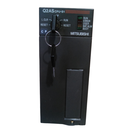
Q2AS(H)CPU(S1)
Mitsubishi Programmable Controller
Thank you for purchasing the Mitsubishi programmable logic controller
MELSEC-QnA series.
Prior to use, please read both this and relevant manual
thoroughly to fully understand the product.
©1996 MITSUBISHI ELECTRIC CORPORATION
User's Manual
Q2ASCPU-U(H/W)-E
MODEL
MODEL
CODE
IB(NA)-66677-H(0810)MEE
(Hardware)
13J857
Advertisement
Table of Contents

Related Manuals for Mitsubishi Q2ASCPU


Summary of Contents for Mitsubishi Q2ASCPU
- Page 1 Q2AS(H)CPU(S1) Mitsubishi Programmable Controller User's Manual (Hardware) Thank you for purchasing the Mitsubishi programmable logic controller MELSEC-QnA series. Prior to use, please read both this and relevant manual thoroughly to fully understand the product. Q2ASCPU-U(H/W)-E MODEL MODEL 13J857 CODE IB(NA)-66677-H(0810)MEE...
- Page 3 SAFETY PRECAUTIONS (Be sure to read these instructions before use.) Before using the product, read this and relevant manuals carefully and handle the product correctly with full attention to safety. In this manual, SAFETY PRECAUTIONS are classified into 2 levels: "DANGER"...
- Page 4 [DESIGN PRECAUTIONS] DANGER (2) When the programmable controller detects the following error conditions, it stops the operation and turn off all the outputs. The overcurrent protection device or overvoltage protection device of the power supply module is activated. The programmable controller CPU detects an error such as a watchdog timer error by the self-diagnostics function.
- Page 5 [DESIGN PRECAUTIONS] DANGER When controlling a running programmable controller (data modification) by connecting a peripheral device to the CPU module or a PC to a special function module, create an interlock circuit on sequence programs so that the whole system functions safely all the time. Also, before performing any other controls (e.g.
- Page 6 [INSTALLATION PRECAUTIONS] CAUTION Use the programmable controller under the environment specified in the user’s manual. Otherwise, it may cause electric shocks, fires, malfunctions, product deterioration or damage. Insert the module fixing projection into the fixing hole in the base unit and then tighten the module mounting screw within the specified torque.
- Page 7 [WIRING PRECAUTIONS] DANGER Be sure to shut off all phases of the external power supply used by the system before wiring. Failure to do so may result in an electric shock or damage of the product. Before energizing and operating the system after wiring, be sure to attach the terminal cover supplied with the product.
- Page 8 [STARTUP AND MAINTENANCE PRECAUTIONS] DANGER Do not touch any terminal during power distribution. Doing so may cause an electric shock. Properly connect batteries. Do not charge, disassemble, heat or throw them into the fire and do not make them short-circuited and soldered. Incorrect battery handling may cause personal injuries or a fire due to exothermic heat, burst and/or ignition.
- Page 9 [DISPOSAL PRECAUTIONS] CAUTION When disposing of the product, treat it as an industrial waste. When disposing of batteries, separate them from other wastes according to the local regulations. (For details of the battery directive in EU member states, refer to the Q2AS(H)CPU(S1) User's Manual.) [TRANSPORTATION PRECAUTIONS] CAUTION...
- Page 10 REVISIONS *The manual number is given on the bottom right of the front cover. Print Date *Manual Number Revision Jan., 1996 IB(NA) 66677-A First edition Sep., 1998 IB(NA) 66677-B Correction SAFETY PRECAUTIONS, Section 4.5.2 Addition Specifications, Performance specifications, EMC standards, Low-Voltage instruction Deletion I/O module specifications and connections...
- Page 11 Japanese Manual Version IB(NA)68653-J This manual confers no industrial property rights or any rights of any other kind, nor dose it confer any patent licenses. Mitsubishi Electric Corporation cannot be held responsible for any problems involving industrial property rights which may occur as a result of using the contents noted in this manual.
-
Page 12: Table Of Contents
CONTENTS 1. SPECIFICATIONS .....................1 1.1 SPECIFICATIONS....................1 2. PERFORMANCE SPECIFICATION................2 2.1 QnASCPU Module Performance Specification .............2 3. EMC DIRECTIVES AND LOW VOLTAGE DIRECTIVES ........3 3.1 Requirements for Compliance with EMC Directives ..........3 3.1.1 EMC standard....................4 3.1.2 Installation instructions for EMC Directive............5 3.1.3 Cables......................6 3.1.4 Power supply module ...................11 3.1.5 Base unit .......................11... - Page 13 6. ERROR CODE......................61 6.1 Error Code Type ....................62 6.2 Reading Error Code.....................62 6.3 Error Code List.....................63 6.4 Canceling of Errors....................225 7. TRANSPORTATION PRECAUTIONS..............226 7.1 Relevant Models ....................226 7.2 Transportation Guidelines .................226 A-11...
- Page 14 This manual explains safety precautions, I/O module wiring, and error codes regarding the Q2ASCPU, Q2ASCPU-S1, Q2ASHCPU, and Q2ASHCPU-S1 (hereinafter, these are all referred to as Q2ASCPU). About this manual The following tables show the manuals relevant to this product. Refer to these tables when you order a manual, if necessary.
- Page 15 Manual number Manual title (Type code) QCPU(Q mode)/QnACPU PROGRAMMING MANUAL (PID Control Instructions) SH-080040 This manual describes specific instructions for PID control for the QnACPU. (13JF59) (sold separately) QCPU(Q mode)/QnACPU PROGRAMMING MANUAL (SFC) This manual describes the system configuration, performance specifications SH-080041 functions, programming, debugging procedures, and the error codes of the (13JF60)
-
Page 16: Specifications
*3: Do not use or store the programmable controller in the environment when the pressure is higher than the atmospheric pressure at sea level. Otherwise, malfunction may result. To use the programmable controller in high-pressure environment, contact your nearest Mitsubishi representative. -
Page 17: Performance Specification
2. PERFORMANCE SPECIFICATION 2.1 QnASCPU Module Performance Specification Performance specification of Q2ASCPU module is as follows: Model Item Remark Q2ASCPU Q2ASCPU-S1 Q2ASHCPU Q2ASHCPU-S1 Control method Repetitive operation of stored program I/O enabled by specifying I/O control method Refresh mode direct I/O... -
Page 18: Emc Directives And Low Voltage Directives
3. EMC DIRECTIVES AND LOW VOLTAGE DIRECTIVES The products sold in the European countries have been required by law to comply with the EMC Directives and Low Voltage Directives of the EU Directives since 1996 and 1997, respectively. The manufacturers must confirm by self-declaration that their products meet the requirements of these directives, and put the CE mark on the products. -
Page 19: Emc Standard
3.1.1 EMC standards When the programmable controller is installed following the directions given in this manual its EMC performance is compliant to the following standards and levels as required by the EMC directive. Specifications Test Item Test Description Standard Values 30M-230 M Hz QP: 30dBμ... -
Page 20: Installation Instructions For Emc Directive
3.1.2 Installation instructions for EMC Directive The programmable controller is open equipment and must be installed within a control cabinet for use.* This not only ensures safety but also ensues effective shielding of programmable controller-generated electromagnetic noise. * : Also, each network remote station needs to be installed inside the control panel. -
Page 21: Cables
3.1.3 Cables The cables pulled out of the control panel contain a high frequency noise component. On the outside of the control panel, therefore, they serve as antennas to emit noise. Ensure to use shielded cables for the cables, which are connected to the I/O modules, special modules and those pulled out to outside of the control panel. - Page 22 Noise in the range of 30 MHz or higher in radiation noise can be suppressed by the use of double-shielded coaxial cables (Mitsubishi Cable: 5C-2V-CCY). Earth the outer shield to the ground. The precautions on shielding to be followed are the same as those stated in item (1) above.
- Page 23 (c) Always use double-shielded coaxial cables as the coaxial cables*2 connected to the 10BASE2 connectors. Earth the double-shielded coaxial cable by connecting its outer shield to the ground. Shield Earth here Refer to (1) for the earthing of the shield. *2: Make sure to install a ferrite core for the cable.
- Page 24 External wiring cable (2 m to 10 m (6.56 ft. to 32.81 ft.)) Drive unit (c) Ferrite core and cable clamp types and required quantities • Cable clamp Type: AD75CK (Mitsubishi Electric) • Ferrite core Type: ZCAT3035-1330 (TDK ferrite core) • Required quantity...
- Page 25 (6) CC-Link Module (a) Be sure to ground the cable shield that is connected to the CC-Link module close to the exit of control panel or to any of the CC-Link stations within 30 cm (11.81 in.) from the module or stations. The CC-Link dedicated cable is a shielded cable.
-
Page 26: Power Supply Module
3.1.4 Power supply module The precautions required for each power supply module are described below. Always observe the items noted as precautions. Model Precautions Make sure to short and ground the LG and FG A1S61PN, A1S62PN terminals. 2 Use the 24VDC panel power equipment conforming to A1S63P 1 the EU Directive. -
Page 27: Noise Filter (Power Supply Line Filter)
3.1.7 Noise filter (power supply line filter) A noise filter is a component which has an effect on conducted noise. With the exception of some models, it is not required to fit the noise filter to the power supply line, but fitting it can further suppress noise. (The noise filter has the effect of reducing conducted noise of 10 M Hz or less.) Use any of the following noise filters (double type filters) or equivalent. -
Page 28: Requirements For Compliance With Low Voltage Directives
3.2 Requirements for Compliance with Low Voltage Directives The Low Voltage Directives apply to the electrical equipment operating from 50 to 1000VAC or 75 to 1500VDC; the manufacturer must ensure the adequate safety of the equipment. Guidelines for installation and wiring of MELSEC-QnA series programmable controller are provided in Section 3.2.1 to 3.2.7 for the purpose of compliance with the EMC Directives. -
Page 29: Power Supply
3.2.3 Power supply The insulation specification of the power module was designed assuming installation category II. Be sure to use the installation category II power supply to the programmable controller. The installation category indicates the durability level against surge voltage generated by a thunderbolt. -
Page 30: Control Panel
3.2.4 Control panel Because the programmable controller is an open device (a device designed to be stored within another module), be sure to use it after storing in the control panel. (1) Electrical shock prevention In order to prevent persons who are not familiar with the electric facility such as the operators from electric shocks, the control panel must have the following functions: (a) The control panel must be equipped with a lock so that only the personnel... -
Page 31: Module Installation
3.2.5 Module installation (1) Installing modules contiguously In Q2AS series programmable controllers, the left side of each I/O module is left open. When installing an I/O module to the base, do not make any open slots between any two modules. If there is an open slot on the left side of a module with 100/200 VAC rating, the printed board which contains the hazardous voltage circuit becomes bare. -
Page 32: Loading And Installation
4. LOADING AND INSTALLATION 4.1 Installing the Module 4.1.1 Notes on handling the module This section explains some notes on handling the CPU module, I/O module, special function module, power supply module, and base unit. (1) Do not drop or allow any impact to the modules case, memory card, terminal block cover, or pin connector. -
Page 33: Installation Environment
4.1.2 Installation environment Avoid the following environment when you install the CPU system: (1) A location in which the ambient temperature falls outside the range of 0 to 55 degrees Celsius. (2) A location in which the ambient humidity falls outside the range of 10 to 90%RH. -
Page 34: Notes On Installing The Base Unit
Take ease of operation, ease of maintenance, and environmental durability into consideration when you are installing the programmable controller on the panel. (1) Mounting dimension Mounting dimensions of each base unit are as follows: POWER MITSUBISHI ELECTRIC CORPORATION BD626E680G52 MADE IN JAPAN E.S.D. A1S38B... - Page 35 (2) Module installation position To maintain good ventilation and make it easy to replace the module, keep the following distances between the top and bottom of the module and the structure or other components. A1S3 B, A1S38HB, A1S38HBEU, A1S5 B(S1), A1S6 B(S1) ..................30 mm (1.18 inch) or over A5 B, A6 B ..............80 mm (3.15 inch) or over This shows the position of the panel's ceiling,...
-
Page 36: Fail-Safe Circuit Concept
(5) Install the unit far from any source of vibration, such as a large magnetic contactor and a no-fuse breaker on the same panel, or install it on a separate panel. (6) Keep the following distance between the programmable controller and other devices (such as a contactor and a relay) in order to avoid the influence of radiated noise and heat: a device installed in front of the programmable controller... - Page 37 Create a safety circuit outside the programmable controller to DANGER ensure the whole system will operate safely even if an external power failure or a programmable controller failure occurs. Install the emergency stop switch outsaid the controlpanel so that workers can operation it easily. Otherwise, incorrect output or malfunction may cause an accident.
- Page 38 For the operation status of each station at a communication DANGER error in data link, refer to the respective data link manual. The communication error may result in an accident due to incorrect output or malfunction. When controlling a running programmable controller (data modification) by connecting a peripheral device to the CPU module or a PC to a special function module, create an interlock circuit on sequence programs so that the whole...
- Page 39 (1) System design circuit example AC system AC/DC system Power supply Power supply DC power supply Transformer established signal Transformer Fuse input Fuse CPU module Start/stop circuit CPU module DC power Can be started SM52 SM52 supply by turning ON of RA1, which is the SM403 (+)(−)
- Page 40 In such cases, all I/O points turn ON or OFF depending on the problem, and normal operation and safety cannot be maintained. Though Mitsubishi programmable controllers are manufactured under strict quality control, they may fail or malfunction due to unspecified reasons. To prevent the whole system failure, machine breakdown, and accidents, build a fail-safe circuit outside the programmable controller.
- Page 41 When constructing a failsafe circuit using ondelay timers only On-delay timer Internal program SM412 On-delay timer 0.5s 0.5s Externai load 24VDC CPU module Output module *1: Use a solid state relay for the M1 relay.
-
Page 42: Wiring
4.3 Wiring 4.3.1 Power supply module specifications (1) Table 4.1 shows the specifications of the power supply modules. Table 4.1 Power supply module specifications Specifications Item A1S61PN A1S62PN A1S63P Base unit position Power supply module slot 24 V DC 100 to 240 V AC (+10 %/-15 %) Rated input voltage (+30 %/-35 %) (85 to 264 V AC) - Page 43 POINT *1: Overcurrent protection The overcurrent proctection device shuts off the 5VDC and/or 24VDC circuit(s) and stops the system if the current exceeding the specified value flows in the circuit(s). As this results in voltage drop, the power supply module LED turns OFF or is dimly lit.
- Page 44 4.3.2 Parts names The following gives the names and description of the parts of the power supply modules: MELSECA MELSECA 1S61PN 1S62PN POWER POWER MITSUBISHI MITSUBISHI INPUT OUTPUT INPUT OUTPUT 100-240VAC 5VDC 5A 100-240VAC 5VDC 3A 105VA 105VA 24VDC 0.6A...
-
Page 45: Wiring Instructions
POINT (1) Do not cable to the unused terminals such as FG and LG on the terminal block (terminals whose name is not printed on the terminal cover). (2) Be sure to ground the terminal LG to the protective ground conductor with class D (class-3) grounding or above. - Page 46 (1) Wiring of power supply (a) When voltage fluctuations are larger than the specified value, connect a constant-voltage transformer. Constant Programmable voltage controller transformer (b) Use a power supply which generates minimal noise between wires and between the programmable controller and ground. If excessive noise is generated, connect an insulating transformer.
- Page 47 (f) Note on using the 24 VDC output of the A1S62PN power supply module. Do not connect multiple power supply modules to one CAUTION module in parallel. The power supply modules may be heated, resulting in a fire or failure. If the 24 VDC output capacity is insufficient for one power supply module, supply 24 VDC from the external 24 VDC power supply as shown below:...
- Page 48 POINT (1) Separate the ground of the surge absorber for lightening (E1) from that of the programmable controller (E2). (2) Select a surge absorber for lightening whose power supply voltage does no exceed the maximum allowable circuit voltage even at the time of maximum power supply voltage elevation.
- Page 49 (3) Grounding Be sure to ground the FG terminals and LG terminals to CAUTION the protective ground conductor. Not doing so could result in electric shock or erroneous operation. (a) Carry out the independent grounding if possible. (Grounding resistance or less.) (b) If the independent grounding is impossible, carry out the shared grounding (2) as shown below.
-
Page 50: Wiring To Module Terminals
4.3.4 Wiring to module terminals This section explains the wiring of power lines and grounding lines to the main and extension bases. Main base unit (A1S38B) Main base unit (A1S38B) 100/110VAC 100/110VAC A1S62PN A1S61PN 200/220VAC 200/220VAC +24V Fuse Fuse (FG) (FG) 24VDC (LG) - Page 51 4.4 Precautions when Connecting the Uninterruptible Power Supply (UPS) Connect the Q2ASCPU system to the uninterruptible power supply (UPS), while paying attention to the followings. Use the on-line UPS or line interactive UPS (voltage distortion of 5% or less.) Alternatively, use the off-line UPS, i.e., FREQUPS-F series with serial number P or later (Mitsubishi).
-
Page 52: Part Names And Settings
4.5 Part names and Settings 4.5.1 Part names and settings This section describes the name and setting of each part of the module. Q2ASCPU, Q2ASCPU-S1, Q2ASHCPU, Q2ASHCPU-S1 Q2ASH STOP L.CLR RESET RESET Illustration of the module with the front cover open... - Page 53 (Set this switch to ON when you wish to access another stations ACPU from the ACPU peripheral device. The setting becomes effective as soon as you set the switch.) :Peripheral device for the ACPU :Peripheral device for the Q2ASCPU RS-422 connector Used to connect a peripheral device.
-
Page 54: Relation Between Switch Operation And The Led Indication
4.5.2 Relation between switch operation and the LED indication (1) Writing a program while the CPU module is stopped: Follow the procedure below to write a program while the CPU module is stopped: RUN/STOP key switch: STOP RUN LED: Off ..CPU module is in STOP mode. Write a program. - Page 55 (3) Removing the memory card while the programmable controller power is on: Operate the memory card load/eject switch as described below the memory card while the programmable controller power is still on: Load/eject switch: ON, Load/eject switch internal LED: Lit..Ejecting the memory card is prohibited.
-
Page 56: Specification And Connection Of I/O Modules
5. SPECIFICATION AND CONNECTION OF I/O MODULES 5.1 Input modules 5.1.1 Input module specifications Operating Voltage No. of Rated Input Input Model Type Points Voltage Current ON voltage OFF voltage A1SX10 100 to 120VAC A1SX10EU AC input 100 to 120VAC 80VAC or higher 30VAC or lower A1SX20 200 to 240VAC... - Page 57 Maximum Internal Max. Response Time Simultaneous Current NO. of Field Points/ Input Points Consump- Occupied (Percentage Wiring Common tion Points Simultaneously OFF to ON ON to OFF (5VDC) 100%(110VAC) 20ms or lower 35ms or lower 60%(132VAC) 100%(110VAC) 20ms or lower 35ms or lower 60%(220VAC) 30ms or lower...
-
Page 58: Input Module Connections
5.1.2 Input module connections Model Rated Input Voltage Model Rated Input Voltage A1SX10 100 to 120 VAC A1SX30 12/24 VAC/DC A1SX10EU A1SX20 200 to 240 VAC A1SX20EU − 12/24VAC 9 and 18 are connected internally. − 12/24VDC 9 and 18 areconnected internally. Do not touch terminals while the DANGER... - Page 59 Model Rated Input Voltage Model Rated Input Voltage A1SX41 12/24 VDC A1SX71 5/24 VDC A1SX41-S1(S2) 24 VDC A1SX42 12/24 VDC B20 A20 A1SX42-S1(S2) 24 VDC A1SX82-S1 B19 A19 B18 A18 B17 A17 B20 A20 B16 A16 B19 A19 B15 A15 B18 A18 B14 A14 B17 A17...
- Page 60 Model Rated Input Voltage A1SX81 12/24 VDC A1SX81-S2 24 VDC − − Vacant Vacant are connected internally.
- Page 61 Model Rated Input Voltage Pin Arrangement A1S42X 12/24 VDC Pin No. Input terminals Internal X38 X30 X28 X20 X18 X10 X08 X00 control circuit X39 X31 X29 X21 X19 X11 X09 X01 X40 X32 X2A X22 X1A X12 X0A X02 X41 X33 X2B X23 X1B X13 X0B X03 X42 X34 X2C X24 X1C X14 X0C X04 X43 X35 X2D X25 X1D X15 X0D X05...
-
Page 62: Output Modules
5.2 Output modules 5.2.1 Output module specifications Max. Output Rated Max. Load Current No. of Response Time Model Type Load Points Voltage Point Common Module OFF to ON ON to OFF 100V to A1SY10 240VAC 24VDC AC100V A1SY to 120V 10EU DC24V 10ms or... - Page 63 External Internal No. of Power Supply Points/ Surge Fuse Error Field Wiring Current Occupied (TYP DC24V) Common Suppression Rating display Consumption Points Current 0.090A 0.12A 0.090A 0.12A None None None 0.1A 0.12A 0.075A 0.24A 0.075A 0.24A CR absorber 0.002A *3 0.27A Terminal CR absorber...
- Page 64 Max. Output Rated Max. Load Current No. of Response Time Model Type Load Points Voltage Point Common Module OFF to ON ON to OFF Transistor Output A1SY71 (for TTL/CMOS) 5/12VDC 0.016A 0.256A 1ms or lower 1ms or lower sink type A1SY80 0.8A 3.2A...
- Page 65 External Internal No. of Power Supply Points/ Surge Fuse Error Field Wiring Current Occupied (TYP DC24V) Common Suppression Rating display Consumption Points Current 40-pin connector None 1.6A 0.15A *4 0.4A Terminal 0.02A 0.12A Zener diode 3.2A 0.008A 0.5A 37-pin D-sub connector Clamp diode None...
-
Page 66: Output Module Connections
5.2.2 Output module connections Model Rated Load Voltage Model Rated Load Voltage A1SY10 240 VAC, 24 VDC A1SY10EU 120 VAC, 24 VDC COM1 − COM1 External load External load power supply power supply COM2 COM2 External load External load − + −... - Page 67 Model Rated Load Voltage Model Rated Load Voltage A1SY22 100 to 200 VAC A1SY28A 100 to 200 VAC COM1 100/200 VAC COM2 100/200 VAC Do not touch Do not touch terminals while the terminals while the DANGER DANGER power is supplied. power is supplied.
- Page 68 Model Rated Load Voltage Model Rated Load Voltage (10) A1SY50 12/24 VDC A1SY60E 5/12/24 VDC A1SY60 24 VDC For a load voltage of 12/24 VDC. + − COM1 − COM2 For a load voltage of 5 VDC. − COM2 + − −...
- Page 69 Model Rated Load Voltage Model Rated Load Voltage (13) A1SY41 A1SY42 12/24 VDC 12/24 VDC A1SY41P (14) A1SY42P B20 A20 B20 A20 B19 A19 B19 A19 B18 A18 B18 A18 B17 A17 B17 A17 B16 A16 B16 A16 B15 A15 B15 A15 B14 A14 B14 A14...
- Page 70 Model Rated Load Voltage Model Rated Load Voltage (15) (16) A1SY81 A1SY71 5/12 VDC 12/24 VDC A1SY81EP B20 A20 B19 A19 B18 A18 B17 A17 B16 A16 B15 A15 B14 A14 B13 A13 B12 A12 B11 A11 B10 A10 + − Vacant Vacant Vacant...
- Page 71 Model Rated Load Voltage (17) A1SY82 12/24 VDC B20 A20 B19 A19 B18 A18 B17 A17 B16 A16 B15 A15 B14 A14 B13 A13 B12 A12 B11 A11 B10 A10 Vacant Vacant Vacant Vacant 5/12VDC 5/12VDC *1 The figure above indicates (the first half 32 points).
- Page 72 Model Rated Load Voltage Pin Arrangement (18) A1S42Y 12/24 VDC Output terminals Pin No. A1S42Y Resistors to limit LED current Internal control circuit Internal YSCN0 Seen from front control face of the module YSCN1 circuit YSCN2 YSCN3 Signal Signal YSCN4 Internal Name Name...
- Page 73 MEMO...
-
Page 74: Input/Output Combined Modules
5.3 Input/output combined modules 5.3.1 Input/output combined module specifications Operating Voltage No. of Input Model Type Rated Input Voltage Points Current Voltage Voltage 8VDC or 4VDC or A1SH42 12/24VDC 2/5mA higher lower 15VDC or 3VDC or A1SH42-S1 24VDC DC Input higher lower (sink type) - Page 75 Max. Response Time No. of Max. Simultaneous Input Points Occupied (Percentage Simultaneously ON) OFF to ON ON to OFF Points 10ms or lower 10ms or lower 60%(24VDC) 0.3ms or lower 0.3ms or lower 100%(26.4VDC) 10ms or lower 10ms or lower External Power External No.
-
Page 76: Input/Output Composite Module Connections
5.3.2 Input/output composite module connections Rated Input Rated Load Model Voltage Voltage A1SH42 12/24 VDC 12/24 VDC A1SH42-S1 B20 A20 B20 A20 B19 A19 B19 A19 B18 A18 B18 A18 B17 A17 B17 A17 B16 A16 B16 A16 B15 A15 B15 A15 B14 A14 B14 A14... - Page 77 Rated Input Rated Load Model Voltage Voltage 24 VDC/ A1SX48Y18 24 VDC 240 VAC − COM1 COM2 + − 24 VDC 24 VDC (For relay drive) Do not touch terminal while the power is supplied. DANGER Rated Input Rated Load Model Voltage Voltage...
-
Page 78: Error Code
6. ERROR CODE If an error occurs when the programmable controller is powered ON, switched to RUN status or running, the Q2ASCPU module executes the self diagnostics function to display the error (LED display, message display) and store the error information into the special relay SM and special register SD. -
Page 79: Error Code Type
6.1 Error Code Type Errors are detected by the self diagnostics function of CPU module or during communication with CPU module. The following table classifies the errors according to the detection pattern, detection location and error code. Error detection Error detection Error code Reference pattern... -
Page 80: Error Code List
: Indicates the Process CPU. QnPRH : Indicates the Redundant CPU. : Indicates the QnA series and Q2ASCPU series. : Indicates the MELSECNET/H remote I/O modules. Each CPU module model name: Indicates the relevant specific CPU module. (Example: Q4AR, Q2AS) - Page 81 • Malfunctioning due to noise or other again, this suggests a CPU module reason hardware fault.(Contact your local • Hardware fault Mitsubishi representative.) Entire program was executed without the execution of an END instruction. • Take noise reduction measures. • When the END instruction is •...
- Page 82 Error Common Individual LED Status Error Diagnostic Code Information Information Operation Message ERROR Timing (SD0) (SD5 to 15) (SD16 to 26) Status At power ON/ At reset/ When 1101 an END instruction executed At power ON/ At reset/ When 1102 an END instruction RAM ERROR...
- Page 83 RAM/program memory in the CPU again,this suggests a CPU module module is faulty. hardware fault.(Contact your local Mitsubishi representative.) • Take noise reduction measures. • Reset the CPU module and RUN it The work area RAM in the CPU module again.
- Page 84 Error Common Individual LED Status Error Diagnostic Code Information Information Operation Message ERROR Timing (SD0) (SD5 to 15) (SD16 to 26) Status 1200 OPE. CIRCUIT At power ON/ 1201 – – Flicker Stop ERR. At reset 1202 1203 When an END OPE.
- Page 85 CPU module does not operate normally. The operation circuit for index This suggests a CPU module hardware 1203 modification in the CPU module does fault. (Contact your local Mitsubishi Q4AR not operate normally. representative.) The hardware (logic) in the CPU 1204 Q4AR module does not operate normally.
- Page 86 Error Common Individual LED Status Error Diagnostic Code Information Information Operation Message ERROR Timing (SD0) (SD5 to 15) (SD16 to 26) Status Module No. (Slot No.) Stop/ FUSE BREAK [For Remote I/ Off/ Flicker/ 1300 – Always O network] Continue Network No./ Station No.
- Page 87 GOT. Any of the mounted modules is experiencing a hardware fault. An interruption has occurred although 1310 Therefore, check the mounted modules there is no interrupt module. and change the faulty module. (Contact your local Mitsubishi representative.)
- Page 88 Error Common Individual LED Status Error Diagnostic Code Information Information Operation Message ERROR Timing (SD0) (SD5 to 15) (SD16 to 26) Status SP. UNIT Module No. At power ON/ 1401 – Flicker Stop DOWN (Slot No.) At reset During SP. UNIT Module No.
- Page 89 1401 error is generated, the head I/O number fault. (Contact your local Mitsubishi of the special function module that representative.) corresponds to the common information is stored.)
- Page 90 Error Common Individual LED Status Error Diagnostic Code Information Information Operation Message ERROR Timing (SD0) (SD5 to 15) (SD16 to 26) Status DUAL DC 1510 – – Continue Always DOWN 5V 1520 DC DOWN 5V – – Flicker Stop Always DC DOWN 1530 –...
- Page 91 Error Corresponding Code Error Contents and Cause Corrective Action (SD0) The power supply voltage (100 to 240VAC) of either of the two power Check the supply voltage of the power supply modules on the power supply supply module. If the voltage is 1510 duplexing extension base unit dropped Q4AR...
- Page 92 Error Common Individual LED Status Error Diagnostic Code Information Information Operation Message ERROR Timing (SD0) (SD5 to 15) (SD16 to 26) Status Module No. (Slot No.) When an END Stop/ UNIT VERIFY [For Remote I/ Off/ Flicker/ 2000 – instruction ERR.
- Page 93 Error Corresponding Code Error Contents and Cause Corrective Action (SD0) • Read the common information of the error using the peripheral device, and check and/or change the module that corresponds to the numerical value (module number) there. I/O module information power ON is •...
- Page 94 Error Common Individual LED Status Error Diagnostic Code Information Information Operation Message ERROR Timing (SD0) (SD5 to 15) (SD16 to 26) Status 2104 SP. UNIT LAY Module No. At power ON/ – Flicker Stop ERR. (Slot No.) At reset 2105 SP.
- Page 95 Error Corresponding Code Error Contents and Cause Corrective Action (SD0) At the MELSECNET/MINI auto refresh Reset the network parameter network parameter settings, the module MELSECNET/MINI auto refresh unit 2104 allocation that was set is different from module allocation setting so that it the actual module models at the station conforms to the station number of the numbers in the link system.
- Page 96 Error Common Individual LED Status Error Diagnostic Code Information Information Operation Message ERROR Timing (SD0) (SD5 to 15) (SD16 to 26) Status 2107 Stop SP. UNIT LAY Module No. At power ON/ 2108 – Flicker ERR. (Slot No.) At reset Stop/ 2109 Continue...
- Page 97 • The location designated by a link fault. Therefore, change the faulty direct device (J \ ) is not a network module. Alternatively, contact your module. local Mitsubishi representative. 2111 • The I/O module (special function module) was nearly removed, completely removed, or mounted during running.
- Page 98 Error Common Individual LED Status Error Diagnostic Code Information Information Operation Message ERROR Timing (SD0) (SD5 to 15) (SD16 to 26) Status When instruction Stop/ SP. UNIT Program error Off/ Flicker/ 2113 FFFF (fixed) executed/ ERROR location Continue STOP At power ON/ 2210 BOOT ERROR Drive name...
- Page 99 Error Corresponding Code Error Contents and Cause Corrective Action (SD0) Read the individual information of the error using a peripheral device, and Data of special function module to be check the special function module / 2113 simulated is not set in the simulation special function module dedicated data.
- Page 100 Error Common Individual LED Status Error Diagnostic Code Information Information Operation Message ERROR Timing (SD0) (SD5 to 15) (SD16 to 26) Status 2401 At power ON/ FILE SET File name/ Parameter Flicker Stop At reset/ ERROR Drive name number At PLC writing 2402 CPU operation can be set in the parameters at error occurrence.
- Page 101 Error Corresponding Code Error Contents and Cause Corrective Action (SD0) • Read the individual information of the error using the peripheral device, check to be sure that the parameter The file specified by parameters cannot drive name and file name correspond 2401 be made.
- Page 102 Error Common Individual LED Status Error Diagnostic Code Information Information Operation Message ERROR Timing (SD0) (SD5 to 15) (SD16 to 26) Status 2410 When Stop/ FILE OPE. File name/ Program error Off/ Flicker/ 2411 instruction ERROR Drive name location Continue executed 2412 2413...
- Page 103 Error Corresponding Code Error Contents and Cause Corrective Action (SD0) • Read the individual information of the error using the peripheral device, check to be sure that the program • The specified program does not exist corresponds to the numerical values in the program memory.
- Page 104 Error Common Individual LED Status Error Diagnostic Code Information Information Operation Message ERROR Timing (SD0) (SD5 to 15) (SD16 to 26) Status 2500 CAN'T EXE. File name/ At power ON/ – Flicker Stop PRG. Drive name At reset 2501 2502 2503 2504 CPU operation can be set in the parameters at error occurrence.
- Page 105 Error Corresponding Code Error Contents and Cause Corrective Action (SD0) • Read the common information of the error using the peripheral device, check to be sure that the parameter • There is a program file that uses a device allocation setting and the device that is out of the range set in program file device allocation the PLC parameter device setting.
- Page 106 Error Common Individual LED Status Error Diagnostic Code Information Information Operation Message ERROR Timing (SD0) (SD5 to 15) (SD16 to 26) Status At power ON/ 3000 PARAMETER File name/ Parameter At reset/ Flicker Stop ERROR Drive name number STOP RUN/ At PLC writing 3001 At power ON/...
- Page 107 • If the same error occurs, it is thought individual information (special register to be a hardware error. (Contact your SD16) are illegal. local Mitsubishi representative.) 3001 The parameter settings are corrupted. • Read the individual information of the error using the peripheral device, check the parameter item When "Use the following file"...
- Page 108 Error Common Individual LED Status Error Diagnostic Code Information Information Operation Message ERROR Timing (SD0) (SD5 to 15) (SD16 to 26) Status At power ON/ LINK PARA. File name/ Parameter 3100 Flicker Stop At reset/ ERROR Drive name number STOP RUN At power ON/ LINK PARA.
- Page 109 • If the error occurs after correction, it parameters have not been written. suggests a hardware fault. (Contact your local Mitsubishi representative.) • Check the network parameters and mounting status, and if they differ, match the network parameters and mounting status.
- Page 110 Error Common Individual LED Status Error Diagnostic Code Information Information Operation Message ERROR Timing (SD0) (SD5 to 15) (SD16 to 26) Status At power ON/ LINK PARA. File name/ Parameter 3103 Flicker Stop At reset/ ERROR Drive name number STOP RUN 3104 At power ON/ LINK PARA.
- Page 111 • If the error occurs after correction, it • AJ71QE71 does not exist in the suggests a hardware fault. (Contact position of I/O number set by the your local Mitsubishi representative.) parameter. • I/O number designation is overlapping. • Numbers of the network parameter and loaded AJ71QE71 are different.
- Page 112 Error Common Individual LED Status Error Diagnostic Code Information Information Operation Message ERROR Timing (SD0) (SD5 to 15) (SD16 to 26) Status 3200 3201 SFC PARA. Parameter File name Flicker Stop STOP ERROR number 3202 3203...
- Page 113 Error Corresponding Code Error Contents and Cause Corrective Action (SD0) The parameter setting is illegal. • Though Block 0 was set to "Automatic 3200 start" in the SFC setting of the PLC parameter dialog box, Block 0 does not exist. Read the common information of the 3201 The block parameter setting is illegal.
- Page 114 Error Common Individual LED Status Error Diagnostic Code Information Information Operation Message ERROR Timing (SD0) (SD5 to 15) (SD16 to 26) Status 4000 4001 At power ON/ At reset/ INSTRCT. Program error STOP RUN – Flicker Stop 4002 CODE ERR location When instruction...
- Page 115 Error Corresponding Code Error Contents and Cause Corrective Action (SD0) • The program contains an instruction code that cannot be decoded. 4000 • An unusable instruction is included in the program. The program contains a dedicated 4001 instruction for SFC although it is not an SFC program.
- Page 116 Error Common Individual LED Status Error Diagnostic Code Information Information Operation Message ERROR Timing (SD0) (SD5 to 15) (SD16 to 26) Status 4100 When Stop/ OPERATION Program error Off/ Flicker/ – instruction ERROR location Continue executed 4101 4102 When Stop/ OPERATION Program error Off/...
- Page 117 Error Corresponding Code Error Contents and Cause Corrective Action (SD0) Read the common information of the error using the peripheral device, check The instruction cannot process the 4100 error step corresponding to its contained data. numerical value (program error location), and correct the problem. •...
- Page 118 Error Common Individual LED Status Error Diagnostic Code Information Information Operation Message ERROR Timing (SD0) (SD5 to 15) (SD16 to 26) Status When FOR NEXT Program error 4200 – Flicker Stop instruction ERROR location executed 4201 When FOR NEXT Program error –...
- Page 119 Error Corresponding Code Error Contents and Cause Corrective Action (SD0) No NEXT instruction was executed following the execution of a FOR 4200 instruction. Read the common information of the Alternatively, there are fewer NEXT error using the peripheral device, check instructions than FOR instructions.
- Page 120 Error Common Individual LED Status Error Diagnostic Code Information Information Operation Message ERROR Timing (SD0) (SD5 to 15) (SD16 to 26) Status 4300 When Stop/ EXTEND Program error Off/ Flicker/ – instruction INST. ERR. location Continue executed 4301 SFCP. CODE Program error 4400 –...
- Page 121 Error Corresponding Code Error Contents and Cause Corrective Action (SD0) The designation of a MELSECNET/ Read the common information of the 4300 MINI-S3 master module control error using the peripheral device, check instruction was wrong. error step corresponding to its The designation of an AD57/AD58 numerical value (program error 4301...
- Page 122 Error Common Individual LED Status Error Diagnostic Code Information Information Operation Message ERROR Timing (SD0) (SD5 to 15) (SD16 to 26) Status 4600 When Stop/ 4601 SFCP. OPE. Program error Off/ Flicker/ – instruction ERROR location Continue executed 4602 4610 SFCP.
- Page 123 Error Corresponding Code Error Contents and Cause Corrective Action (SD0) The SFC program contains data that 4600 cannot be processed. Read common information of the error Exceeds device range that can be using the peripheral device, check error 4601 designated by the SFC program. step corresponding to its numerical The START instruction in an SFC value (program error location), and...
- Page 124 Error Common Individual LED Status Error Diagnostic Code Information Information Operation Message ERROR Timing (SD0) (SD5 to 15) (SD16 to 26) Status 4630 When 4631 STEP EXE. Program error – Flicker Stop instruction ERROR location executed 4632 4633 CPU operation can be set in the parameters at error occurrence. (LED indication varies.)
- Page 125 Error Corresponding Code Error Contents and Cause Corrective Action (SD0) Read common information of the error Startup was executed at a block in the using the peripheral device, check error 4630 SFC program that was already started step corresponding to its numerical value (program error location), and correct the problem.
- Page 126 Error Common Individual LED Status Error Diagnostic Code Information Information Operation Message ERROR Timing (SD0) (SD5 to 15) (SD16 to 26) Status Time (value Time (value 5000 WDT ERROR actually Flicker Stop Always set) measured) Time (value Time (value 5001 WDT ERROR actually Flicker...
- Page 127 Error Corresponding Code Error Contents and Cause Corrective Action (SD0) • Read the individual information of the error from the peripheral device, check its value (time), and shorten • The scan time of the initial execution the scan time. type program exceeded the initial •...
- Page 128 Error Common Individual LED Status Error Diagnostic Code Information Information Operation Message ERROR Timing (SD0) (SD5 to 15) (SD16 to 26) Status PRG. VERIFY 6000 File name – Flicker Stop Always ERR. MODE. 6010 – – Continue Always VERIFY ERR. At power ON/ TRUCKINERR 6100...
- Page 129 Hardware fault of the CPU module. (Please contact your local nearest A CPU module tracking memory error Mitsubishi or sales representative, was detected during initial. explaining a detailed description of the 6100 (This can be detected from the control Q4AR problem.
- Page 130 Error Common Individual LED Status Error Diagnostic Code Information Information Operation Message ERROR Timing (SD0) (SD5 to 15) (SD16 to 26) Status Reason(s) for CAN'T EXE. At switching 6220 system – Continue CHANGE request switching Reason(s) for CAN'T EXE. At switching 6221 system –...
- Page 131 This is a bus switching module switching module error. 6221 hardware fault. (Contact your local (This can be detected from the control Mitsubishi representative.) system of the redundant system.) Q4AR The link module mounted on the 6230 standby system CPU module is the Check the system configuration status.
- Page 132 Error Common Individual LED Status Error Diagnostic Code Information Information Operation Message ERROR Timing (SD0) (SD5 to 15) (SD16 to 26) Status When Program error Annunciator 9000 F**** Continue instruction location number executed USER LED On When <CHK>ERR Program error 9010 Failure No.
- Page 133 Error Corresponding Code Error Contents and Cause Corrective Action (SD0) Read the individual information of the error using the peripheral device, and 9000 Annunciator (F) was set ON check the program corresponding to the numerical value (annunciator number). Read the individual information of the error using the peripheral device, and 9010 Error detected by the CHK instruction.
-
Page 134: Canceling Of Errors
6.4 Canceling of Errors Q series CPU module can perform the cancel operation for errors only when the errors allow the CPU module to continue its operation. To cancel the errors, follow the steps shown below. 1) Eliminate the cause of the error. 2) Store the error code to be canceled in the special register SD50. -
Page 135: Transportation Precautions
7. TRANSPORTATION PRECAUTIONS When transporting lithium batteries, make sure to treat them based on the transportation regulations. 7.1 Relevant Models The batteries for the QnACPU are classified as shown in the table below. Product Name Model Description Handled As QnA series battery A6BAT Lithium battery Non-dangerous goods... - Page 136 MEMO...
- Page 138 Warranty Mitsubishi will not be held liable for damage caused by factors found not to be the cause of Mitsubishi; machine damage or lost profits caused by faults in the Mitsubishi products; damage, secondary damage, accident compensation caused by special factors unpredictable by Mitsubishi;...
Need help?
Do you have a question about the Q2ASCPU and is the answer not in the manual?
Questions and answers