Table of Contents
Advertisement
Quick Links
Advertisement
Table of Contents

Subscribe to Our Youtube Channel
Related Manuals for Mitsubishi QD75M1


Summary of Contents for Mitsubishi QD75M1
- Page 1 Positioning Module User's Manual (Hardware) QD75M1 QD75M2 QD75M4 Thank you for buying the Positioning Module. Prior to use, please read both this manual and detailed manual thoroughly and familiarize yourself with the product. ©2000 MITSUBISHI ELECTRIC CORPORATION...
-
Page 3: Safety Instructions
SAFETY INSTRUCTIONS (Always read these instructions before using this equipment.) Before using this product, please read this manual and the relevant manuals introduced in this manual carefully and pay full attention to safety to handle the product correctly. The instructions given in this manual are concerned with this product. For the safety instructions of the programmable controller system, please read CPU module User's Manual. - Page 4 [WIRING PRECAUTION] DANGER Completely turn off the externally supplied power used in the system before installing or placing wiring. Not doing so may cause electric shock or damage to the product. CAUTION Check the layout of the terminals and then properly route the wires to the module. Solder connectors for external input signal cable and SSCNET cable properly.
- Page 5 This manual confers no industrial property rights or any rights of any other kind, nor does it confer any patent licenses. Mitsubishi Electric Corporation cannot be held responsible for any problems involving industrial property rights which may occur as a result of using the contents noted in this manual.
-
Page 6: Table Of Contents
Conformation to the EMC Directive and Low Voltage Instruction For details on making Mitsubishi PLC conform to the EMC directive instruction when installing it in your product, please refer to Chapter 3, "EMC Directive and Low Voltage Instruction" of the using PLC CPU module User's Manual( Hardware). -
Page 7: Overview
1. Overview This manual explains how to handle the Positioning Module, model numbers QD75M1, QD75M2, QD75M4 (hereinafter collectively referred to as the QD75). After unpacking the QD75, please verify that the corresponding product as listed below is enclosed in the package. -
Page 8: Specifications
2. Specifications (1) The specifications for the QD75M1, QD75M2 and QD75M4 Specification Item QD75M1 QD75M2 QD75M4 Number of axes (axis) For connection of QD75M and MR-J2-B/MR-J2S-B/ MR-J2-Jr/MR-J2M-B. For connection of MR-J2-B/MR-J2S-B/MR-J2- Jr/ MR-J2HBUS M MR-J2M-B and MR-J2-B/MR-J2S-B/MR-J2- Jr/ (Note-1) MR-J2M-B. -
Page 9: Handling
3. Handling CAUTION Use the PLC within the general specifications environment given in the CPU module User's Manual to use. Using the PLC outside the general specification range environment could lead to electric shocks, fires, malfunctioning, product damage or deterioration. While pressing the installation lever located at the bottom of module, insert the module fixing tab into the fixing hole in the base unit until it stops. -
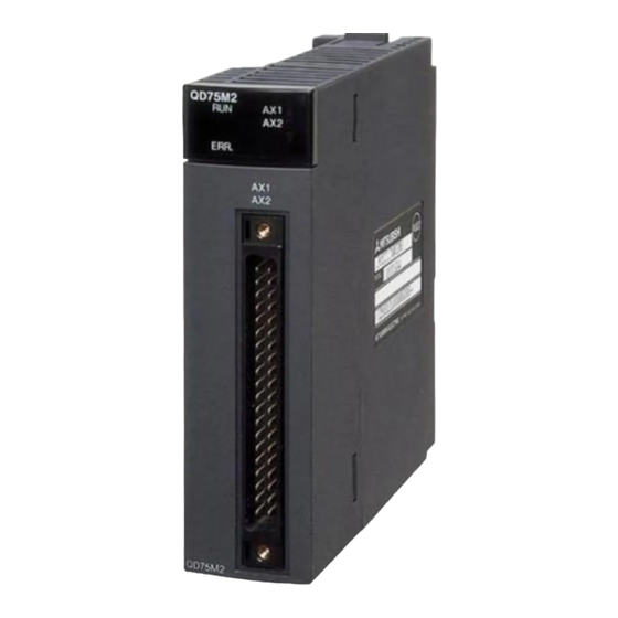
Page 10: Names Of Each Part
4. Names of Each Part (1) Names of each part (a) QD75M1 (b) QD75M2 (c) QD75M4 QD75M1 QD75M2 QD75M4 QD75M4 QD75M1 QD75M2 Name Name LED display SSCNET cable connector External input signal cable connector (2) Contents of LED display LED name... - Page 11 (3) Signal layout for external device connection connector Axis 4 (AX4) Axis 3 (AX3) Axis 2 (AX2) Axis 1 (AX1) Pin layout Pin No. Signal name Pin No. Signal name Pin No. Signal name Pin No. Signal name 2B20 No connect 2A20 No connect 1B20 PULSER B- 1A20 PULSER B+...
-
Page 12: Wiring
5. Wiring DANGER Completely turn off the externally supplied power used in the system before installing or placing wiring. Not doing so may cause electric shock or damage to the product. CAUTION Check the layout of the terminals and then properly route the wires to the module. Solder connectors for external input signal cable and SSCNET cable device properly. -
Page 13: Wiring Precautions
5.1 Wiring Precautions (1) Use separate cables for connecting to the QD75 and for the power cable that create surge and inductance. (2) The cable for connecting QD75 can be placed in the duct or secured in place by clamps. If the cable is not placed in the duct or secured by clamps, unevenness or movement of the cable or careless pulling on it could result in damage to the unit or cable or defective cable connections could cause mis-operation of the unit. - Page 14 [Processing example of shielded cables] Connections of FG wire and each shielded cable Remove the covering from all shielded cables and bind the appeared shield with a conductive tape. Coat the wire with insulaing tape. Solder the shield of any one of the shielded cables to the FG wire.
-
Page 15: Sscnet Cable Precautions
(5) To make this product conform to the EMC directive and low voltage instruction, be sure to used of a AD75CK type cable clamp (manufactured by Mitsubishi Electric) for grounding connected to the control box and the shielded cable/ the SSCNET cable. -
Page 16: External Interface
5.3 External Interface The outline diagrams of the internal circuits for the QD75M1 external device connection interface are shown below. (1) Input Need for wiring External wiring Pin No. Internal circuit Signal name (Note-1) When upper-limit switch is not used... -
Page 17: External Dimensions
6. External Dimensions QD75M1 QD75M2 QD75M4 QD75M1 QD75M2 QD75M4 QD75M4 QD75M1 QD75M2 27.4(1.08) 46(1.81) 90(3.54) 136(5.35) Unit : mm (inch) - Page 18 Warranty Mitsubishi will not be held liable for damage caused by factors found not to be the cause of Mitsubishi; machine damage or lost profits caused by faults in the Mitsubishi products; damage, secondary damage, accident compensation caused by special factors unpredictable by Mitsubishi; damages to products other than Mitsubishi products;...
Need help?
Do you have a question about the QD75M1 and is the answer not in the manual?
Questions and answers