Table of Contents
Advertisement
Quick Links
Advertisement
Table of Contents

Subscribe to Our Youtube Channel
Related Manuals for sauter SW 1000


Summary of Contents for sauter SW 1000
- Page 1 Sauter GmbH Ziegelei 1 Telephone: +49-[0]7433-9933-199 D-72336 Balingen Fax: +49-[0]7433-9933-149 E-mail: info@sauter.eu Web: www.sauter.eu Instruction Manual Sound Level Meter SAUTER SW 1000/SW 2000 Version 1.0 05/2017 PROFESSIONAL MEASUREMENTS SW-BA-e-1710...
-
Page 2: Table Of Contents
User Manual Sound Level Meter Congratulations on your purchase of a high-quality sound level meter by SAUTER. We wish you a lot of pleasure and satisfaction in using our top-quality gauge with a comprehensive range of functions. Should you have any questions, we remain at your disposal. - Page 3 4.3.11 Timer ............................27 4.3.12 24 h Measurement with Timer ....................28 4.4 Setup ............................... 29 4.4.1 Contrast ............................29 4.4.2 Backlight ............................29 4.4.3 Battery ............................29 4.4.4 Trigger ............................30 4.4.5 Date & Time ..........................30 4.4.6 Auto Power Off ..........................31 4.4.7 RS-232 ............................
- Page 4 Appendix 6 ......................52 Technical data of 1/1-octave filter ................. 52 SW-BA-e-1710...
-
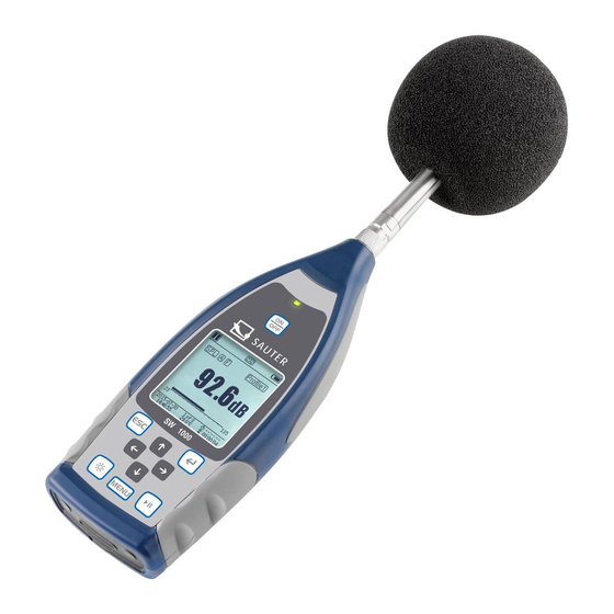
Page 5: Appearance
Appearance Microphone and pre-amplifier LED indicator Anti-slip surface Battery Illuminated LCD LR6/AA/AM3 display Power socket (7–14 V) AC/DC output switch SW-BA-e-1710... -
Page 6: Operating Keys
The new algorithm supports only one measuring range which includes a dynamic range above 120 dB, but despite that it still meets the requirements of the standard. The SW 1000 meter is a Class 1 gauge, and the SW 2000 is a Class 2 gauge. SW-BA-e-1710... -
Page 7: Applications
The 1/1-octave analyser is in accordance with IEC 61260-1:2014 and ANSI S1.11- 2004 Linearity range: 20 dBA to 134 dBA (SW 1000), 25 dBA to 136 dBA (SW 2000) Dynamic range: above 123 dB for SW 1000 and above 122 dB for SW 2000 ... -
Page 8: Specification
1.5 Specification Technical data Type SW 1000 SW 2000 Accuracy Class 1 (Group X) Class 2 (Group X) GB/T 3785.1-2010, IEC 60651:1979, IEC 60804:2000 Standard IEC 61672-1:2013, ANSI S1.4-1983, ANSI S1.43-1997 average frequencies of the 1/1-octave filter: 31.5 Hz to average frequencies of the 1/1-octave filter: 31.5 Hz to... - Page 9 Resolution 24 bits Sampling 48 kHz frequency displaying noise characteristics as a function of time, Time history duration of measurement: 1 minute, 2 minutes, 10 minutes LCD display, 160 x 160, with white backlight, LCD indicator 14 contract levels, readouts updated every 1 s Bulk storage microSD (TF) card with a capacity of 4 GB VA-SLM software for final processing: readout, analysis and re-...
-
Page 10: Information On Regular Tests
For the BSWA 200 gauges, any result above 12.5 kHz can be ignored due to the frequency response of the microphone installed in Class 2 gauges. Hint 2: The data were measured using a 50 mV/Pa microphone for SW 1000 meter and a 40 mV/Pa microphone for BSWA 200 meter. Hint 3: The measurement meets the requirements of GB/T3785 and IEC 61672 standards. -
Page 11: Graphic Representation Of Delivery Package
☆ Hint: The details specified in the list of parts may differ depending on the delivery. 2 View and operation The look of SW 1000 and SW 2000 gauges and keyboards is identical. The LCD dis- play, keyboard and LED indicators are located on the front side. -
Page 12: Microphone Port
(normally the microphone and pre-amplifier are installed together in a single casing). The TNC connector is a threaded concentric connector. The SW 1000 gauge is equipped with a Class 1 microphone, and the SW 2000 gauge – with a Class 2 microphone: SW-A01: Pre-polarised 1/2”... -
Page 13: Wind Shield
4 mA, 24 V. Voltage over 30 V may cause damage to the micro- phone. The SW 1000/SW 2000 sound level meter is equipped with an internal ICCD power supply which allows a direct connection of a microphone. -
Page 14: Battery
be used as an additional external power supply; the power supply must provide 5 V/1 A. USB Disk Mode: It enables a direct interference in the files stored in the mi- croSD card; it does not require driver installation. The miniUSB port is detected by the computer as a serial port (virtual serial port, driver installation required), and the communication with the sound level meter is via the RS-232 interface;... -
Page 15: Gps
ously for almost 12 hours. If the battery voltage drops below the minimum voltage required for the meter operation, the gauge will automatically switch off. In case of a long operation, we recommend using an external power supply or USB power supply. -
Page 16: Measurement Screen
is lower during rain or indoors. The GPS mode has 3 start modes: cold start, warm start and hot start. The initial position determination, when the current ephemerides must be downloaded, requires more time. The GPS module stores the last location information data saved, but it requires another downloading of the ephemerides, as they are obsolete. -
Page 17: Screen In The Level Measurement Mode
is deactivated. Trigger status. It is shown when the trigger is active. RS-232 interface status. The symbol is shown in the re- mote mode, and the symbol — in the printer mode. Timer status. The symbol indicates that the timer is ac- tive and was activated only once. - Page 18 3 profiles Indication of data and the relevant measurement mode, information on the filter and profiled measurement detec- tor. The data of the 3 profiles can be saved in a single SWN file. LN statistics Showing 10 groups of statistical results. Each group of data source can be adjusted (a fixed mode for SPL, filter and detector), and the percentage can be set in the menu.
-
Page 19: 1/1 Octave Mode Screen
GPS screen 2 Display of the number of satellites used to determine the position and the signal-to-noise ratio for all the visible sat- ellites (0–99 dB). ☆ Hint: The number of visible satellites can be higher than the number of satellites used to determine the posi- tion, as many satellites are not available for position de- termination. -
Page 20: Operation And Setting The Menu
4. Operation and setting the menu Press <MENU> to show the next menu. All the measurement pa- rameters can be set in the menu. Menu tree 4.1 Function Select Function and press <ENTER> to open this menu. You can choose 2 types of measurement. Level measurement and 1/1-octave measurement. -
Page 21: Calibration By Measurement
4.2.1 Calibration by measurement To open this menu, select By Measurement and press <EN- TER>. Further details concerning the calibrator used and the ap- propriate adaptation value are provided in Appendix 2, Adaptation of Control Calibration Frequency. The calibration level can be adapted within a range from 0 dB to 199.9 dB. - Page 22 Calibration by measurement is performed as follows: Insert the microphone all the way into the calibrator cavity; it must be firmly settled. Switch on the calibrator and set a fixed sound level (e.g. 94 dB). To open the By Measurement menu, select Calibration and press <ENTER>. In the menu, set the Cal.Level value to e.g.
-
Page 23: Measurement
To start the measurement, open the home screen again and press <START/STOP>. If the calibrator works properly, for the example given in this manual the current measurement result is 93.8 dB. 4.3 Measurement The Measurement menu includes 13 options. Using the navigation keys <▲> and <▼>, you can choose the options and open the next menu by pressing <ENTER>. - Page 24 tave bands and the parameters LAeq, LBeq, LCeq, LZeq are saved as an OCT file. SWN-Log.Step: SWN-Log.Step is a logging step (step period) used to save the data as SWN/OCT files. With the <◄> and <►> keys, you can choose the following op- tions: 0.1 s, 0.2 s, 0.5 s, 1 s to 59 s, 1 min to 59 min, 1 h to 24 h.
-
Page 25: Measuring Range
4.3.2 Measuring range The MEAS.Range includes the Linearity Range, Dynamic Range and Peak C Range. With the new algorithm, there is only one measuring range, so switching between the ranges is not required. The algorithm meets the requirements of a pulse frequency response of up to 0.25 ms with an error being as low as 0.1 dB at 4 kHz. -
Page 26: Alarm Threshold
screen. With the <◄> and <►> keys, you can choose the following options: LEQ, PEAK, MAX or MIN. 4.3.5 Alarm Threshold If the measurement results for Profiles 1–3 exceed the Alarm Threshold, the red LED above the <POWER> key will light up. The alarm threshold can be set within a range from 20 dB to 200 dB. -
Page 27: Time History
4.3.8 Time History With the navigation keys <▲> and <▼>, you can set the data source and duration of the time history. Profile: With the navigation keys <◄> and <►>, you can set the data source for the time history: Profile 1, Profile 2, Profile 3. Duration: With the navigation keys <◄>... -
Page 28: 24 H Measurement With Timer
In the timer menu, the Timer option allows you to set the Start Day, Start Time and Repeat Interval. Press the navigation keys <▲> and <▼> to choose the option. To enable a programmed start of measurement, we introduced a new function called Timer. -
Page 29: Setup
In order to always restart the measurement, set the Timer to Loop. Set the required date as the Start Day. Set the Start Time to 00:00. This is the time when the measurement will be initially activated. In order for the measurement to be reactivated every hour, set Repeat Interval to 1 h. -
Page 30: Trigger
4.4.4 Trigger The Trigger menu allows you to activate or deactivate the trigger function. Trigger is the analogue input which, using remote con- trol commands, enables starting or stopping a measurement per- formed with the sound level meter. The trigger input is located in at the bottom of the meter (3.5 mm headphone port). -
Page 31: Auto Power Off
☆ Hint: The system clock installed in the sound level meter was calibrated using a reference clock with an average error of 2 ppm (maximum error: 3 ppm). The time accuracy at room temperature is below 10 ppm (< 26 s in 30 days). The maximum time error during internal tests at 25°C was approx 5–8 s. -
Page 32: Rs-232
4.4.7 RS-232 The RS-232 menu allows to set a serial port option, see section 5 RS-232 Data Exchange Protocol. RS-232 Mode: RS-232 options: Remote, Printer. Press the navigation keys <◄> and <►> to choose an option. In the Remote mode, the RS-232 port provided in the sound level meter enables control and data transmission. -
Page 33: Boot Mode
In the OCT File menu, you can delete the OCT file. The procedure is the same as for the SWN File. In the CSD File menu, you can delete, display or print the content of the CSD file. By pressing the navigation keys <▲>... -
Page 34: Usb Mode
device can be integrated with another system, especially if there is a risk of power outage. In case of operating voltage loss, the sound level meter will automatically restart. Boot & Auto Meas.: In this case, the hardware mode switch should be set to Boot. Once this mode is selected, not only the sound level meter will boot upon the supply of operating voltage, but the device will also start measuring. -
Page 35: Gps
Modem Mode: In this case, after the device is connected to a computer using a USB cable, it will always operate in the Modem Mode without showing the question. The sound level meter can be detected by the computer as a serial (virtual) port us- ing the same protocol as RS-232 interface (further details, see section 5. -
Page 36: Output
4.6 Output The Output menu allows you to choose the measurement data sent to the DC OUT. For the level meter and 1/1-octave modes, the options specify the DC output of the level meter and the 1/1-octave DC output. The menu also offers the Printer option. Press the navigation keys <▲>... -
Page 37: Printer
4.6.3 Printer The Print option allows to set the automatic or manual printing mode. If you choose Auto, the measurement results will be printed automati- cally once the measurement is stopped. If you choose Manual, you will have to click Print Now and press <ENTER>... -
Page 38: Rs-232 Data Transmission Protocol
5.2 Transmission protocol The RS-232 interface protocol used in SW 1000/200 is based on a block transmis- sion corresponding to the following pattern: A typical command block or response block consists of a start-of-text character, iden-... -
Page 39: Beginning And End Of Block Transmission
5.2.1 Beginning and end of block transmission The command or response block contains a start character, end character and other control characters described in the table below: Name Value in hexadecimal sys- Meaning <STX> Start of text <ETX> End of text <CR>... -
Page 40: Block Transmission Format
BCC value is 00H, the sound level meter does not check the data, and the authorised instruction is processed directly. This way you can simplify the transmission of an instruction block, but this method is not recommended for long-distance transmis- sions, as the BCC value is the only possibility to ensure the reliability of data trans- mission. -
Page 41: Restoration After Transmission Errors
5.2.6 Restoration after transmission errors Various errors can occur during a transmission of command block or response block. Below we present the manner in which the sound level meter treats the errors and restores the original status. (1) Incomplete block transmission The four block transmission formats are specified in section 5.2.5. -
Page 42: Nominal Parameters
meters in an equivalent network using broadcast instructions, or access the data and parameters of each individual sound level meter using the regular commands. Note that: (1) Sound level meters within the same network may never have the same IDs. (2) Using the broadcast instructions, you cannot send commands returning any data. -
Page 43: Operation Guidelines
► instruction: ◄— response (3) Query: Acknowledge: Query — Sound Level Meter ► instruction Computer ◄— Feedback Negative acknowledge: Query — ► instruction Sound Level Meter Computer ◄— response 6. Operation guidelines 6.1 Operation Minimise the effect of vibration when using the sound level meter. Mechanical vi- bration may have an adverse impact on the indications at the lower measurement limit range, within the frequency range of the sound level meter (10 Hz to 20 kHz). -
Page 44: Calibration
BSWA offers calibration services for acoustic products. 6.4 Firmware updating The firmware of SW 1000/SW 2000 can be updated using the USB interface. The following equipment components must be available: the sound level meter SW 1000/SW 2000 must be deactivated (identifier HWID P0274 or higher), ... -
Page 45: Firmware Updating Procedure
When the driver is installed, connect the sound level meter to the computer using the USB cable. The Device Manager will show a new device called Silicon Labs CP210x USB to UART Bridge (COMx). ☆ Hint: When the sound level meter connects to the computer, power it up using an external power supply. -
Page 46: Warranty
Step 4: Press the key located in the upper right corner to choose the firmware, and then press Update to start the program. The whole procedure takes 3 to 4 minutes. ☆ Hint: The device should be reset to the factory set- tings, and after updating the firmware perform at least one calibration, otherwise the sound level meter may work improperly. - Page 47 sponse. The A and C weightings are used more often and defined in IEC and GB/T standards. The B weighting is only defined in ANSI standard. The D weighting re- fers to an international standard that is already invalidated. The D weighting is only available in some old devices.
-
Page 48: Weightings For The Sound Level Meter And Sound Broadcasting Around The Microphone At Typical Building Reflections
Appendix 2 Weightings for the sound level meter and sound broadcasting around the microphone at typical building reflections Korrekturen für typische Reflexionen vom Gehäuse des Schalldruckmessgeräts und Schallstreuung um das Mikrofon -0,5 -1,0 -1,5 Fre- Valu Fre- Valu Fre- Valu Fre- Valu Fre-... -
Page 49: Weightings Related To The Use Of A Wind Shield Outdoors
Appendix 3 Weightings related to the use of a wind shield outdoors Korrekturen des Windschutzes im freien Feld -0,5 -1,0 -1,5 -2,0 Frequency Frequency Frequency Value [dB] Value [dB] Value [dB] [Hz] [Hz] [Hz] *50.119 -0.04 *398.11 0.06 3162.3 0.12 *63.096 0.04 *501.19... -
Page 50: Electret Microphone Weightings
Appendix 4 Electret microphone weightings The weightings given below were measured with an electret microphone and power supply. Korrekturen des Elektretmikrofons 10,0 Frequency Value Frequency Value Frequency Value Frequency Value [Hz] [dB] [Hz] [dB] [Hz] [dB] [Hz] [dB] 0.000 0.043 2000 0.312 6300... -
Page 51: Typical Frequency Response And Corresponding Upper Limits
31.5 16 k* A-weighting [dB] -39.5 -26.2 -16.2 -8.7 -3.3 +1.3 +1.2 -0.5 -9.7 B-weighting [dB] -17.1 -9.4 -4.3 -1.4 -0.3 -0.5 -2.3 -11.6 C-weighting [dB] -3.0 -0.8 -0.2 -0.1 -0.6 -2.4 -11.7 Hint*: Available only in SW 1000. SW-BA-e-1710... - Page 52 Appendix 6 Technical data of 1/1-octave filter The 1/1-octave filter was developed based on the Butterworth filter, grade 10. The technical data for each filter are presented in the following figure. 31.5Hz~500Hz Octave Filter 10,0 -10,0 -20,0 -30,0 -40,0 -50,0 -60,0 -70,0 -80,0...
Need help?
Do you have a question about the SW 1000 and is the answer not in the manual?
Questions and answers