Table of Contents
Advertisement
Quick Links
Advertisement
Table of Contents

Subscribe to Our Youtube Channel
Related Manuals for sauter SAUTER TG


Summary of Contents for sauter SAUTER TG
- Page 1 Sauter GmbH Ziegelei 1 Phone : +49-[0]7433- 9933-0 D-72336 Balingen Fax: +49-[0]7433-9933-149 e-mail: info@kern-sohn.com Internet: www.sauter.eu Instruction Manual Digital Coating Thickness Gauge SAUTER TG/TF Version 2.0 04/2020 TF 1250-0.1FN TG 1250-0.1FN PROFESSIONAL MEASURING TG_TF-BA-e-2020...
-
Page 2: Table Of Contents
Instruction Manual Digital Coating Thickness Gauge Thank you for purchasing a digital coating thickness gauge from SAUTER. We hope you will be very satisfied with the high quality of this measuring device and its extensive functionality. For any questions, wishes and suggestions please do not hesitate to contact us. -
Page 3: Introduction
1. Introduction 1.1 General description This coating thickness gauge is small, light and handy. Although it has complex and advanced equipment, it is convenient and easy to use. Its robustness allows it to be used for many years, provided that all instructions in this manual are carefully followed. -
Page 4: Technical Data
3. Technical data TE 1250-0.1F TE 1250-0.1FN TE 1250-0.1N Display 4 digits, 10mm LCD display with backlight 0 to 1250 μm / 0 to 50 mil (standard) Measuring range Resolution 0,1 µm (0 to 99,9 µm), 1 µm (over 100) 3 % of the measured value or Min ±... -
Page 5: Front Panel Description
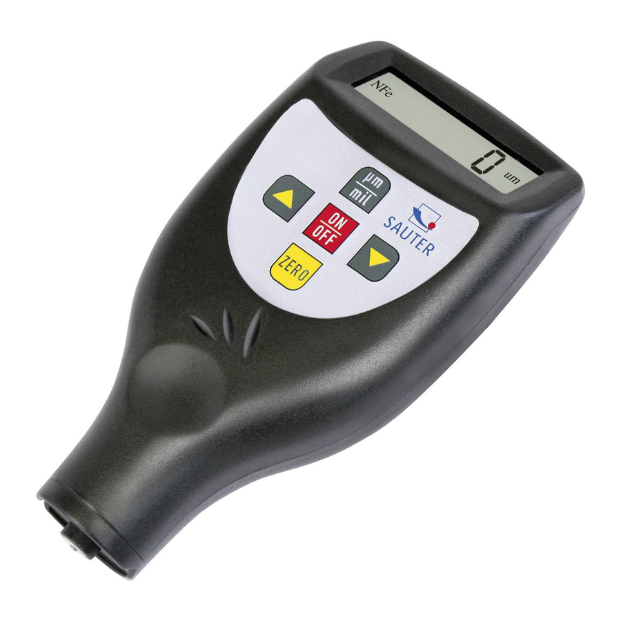
4. Front panel description here: Model TF, with inbuilt sensor Sensors inbuilt at model TF ( F and N) or at model TG with external sensor FN Display Power-key/Zero- key Plus- key (arrow button up) Minus- key ( arrow button down) Reading key (READ- key) Delete key (DEL-key) Socket for RS-232 interface... -
Page 6: Measurement Procedure
5. Measurement procedure 4.1 The power key 3-3 has to be pressed to switch on the instrument. `0` appears on the display 3-2. Both instruments, TF and TG, will recognize the mode of the last measurement itself by the symbol appearing in the display `Fe` (= F) for ferrous metals or `NFe` (= N) for non-ferrous metals. -
Page 7: How To Store And Recall Readings
To clear the statistical data before starting a new set of data, the Zero-key 3-3 just has to be pressed and released. In measurement mode, which is marked by SV, the last value can be deleted by pressing the DEL-key. Statistics is re-calculated and displayed again. -
Page 8: Calibration
10. Calibration 9.1 Zero adjustment Zero adjustment for `Fe` and `NFe` should be carried out separately. The iron base plate has to be used if `Fe` is being displayed. The base plate of aluminium has to be used if `NFe` is shown on the display. The sensor 3-1 has to be placed carefully onto the base plate. -
Page 9: Correct Handling At Coating Thickness Measurement With External Sensors
This instrument has included in delivery a set of adjustment foils with different foils and thicknesses, whereupon the measurement range of 20 up to 2000µm will always be covered. These adjustment foils are also available as an optional accessory, article number ATB-US07. -
Page 10: Annotations
until `CAL` appears on the display. This lasts about 12 seconds from starting pressing the Power-key. 14.2.3 If now NF:H appears in the display, the sensor has to be lifted for more than 5cm. Then the Zero- key has to be pressed and the instrument returns into measurement mode.
Need help?
Do you have a question about the SAUTER TG and is the answer not in the manual?
Questions and answers