
Related Manuals for sauter FC 10


Summary of Contents for sauter FC 10
- Page 1 Sauter GmbH Ziegelei 1 Tel: +49-[0]7433- 9933-0 D-72336 Balingen Fax: +49-[0]7433-9933-149 E-Mail: info@kern-sohn.com Internet: www.sauter.eu Instruction Manual Digital Force Gauge SAUTER FC Version 1.0 02/2014 FC-BA-e-1410...
-
Page 2: Table Of Contents
SAUTER FC Version 1.0 01/2014 Instruction Manual Digital Force gauge Summarize General Specifications .................. 4 Overview ............................ 4 LCD Screen ..........................4 Key Functions ........................... 5 Specifications ........................... 5 Operation ......................5 Preparation ..........................5 Testing ............................6 Save the measured value ......................7 Browse and print data ...................... - Page 3 NOTICE Please carefully read this first 1. During the test, please wear protective masks and gloves, because splashes could injure your body. 2. DO NOT exceed the capacity of the gauge. At 110% of the capacity, the display flashes and the alarm sounds; please remove the load immediately. If 150% of the rated capacity is exceeded, the load cell may be damaged forever.
-
Page 4: General Specifications
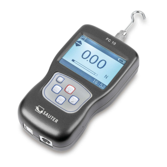
1 General Specifications 1.1 Overview Fig 1-1 1.2 LCD Screen Fig 1-2 ① Test mode icon: :Track, :Peak, :Preset ② Battery icon: Indicating the battery level or charging status, flashes if the ③ Preset Mode Test status mark gauge needs to be recharged :... -
Page 5: Key Functions
④ Test units: Displays selected measuring unit (N, kgf, ozf, and lbf selectable) : The measured value higher than the upper limit ⑤ System time ⑥ Data transmission icon ⑦ Data storage icon ⑧ Analogue bar ⑨ Current measured value ⑩... -
Page 6: Testing
Choose the adapter In order to complete the test work convenient, the standard force gauge is equipped with a variety of measuring heads. According to the actual need, please select the appropriate measurement adapter, shown in Fig 2-1: Flat Conical Chisel Notched Hook Extension rod Fig 2-1 2.2 Testing... -
Page 7: Save The Measured Value
Preset: In this mode, you can set the tolerance upper limit and lower limit of meas- ured force value to do a GO/NG measurement. See chapter 3.2. ④ Before measurement, you should zero the tare by pressing ⑤ The force gauge often is used hand-held. But mounting it on a test stand for use may be more accurate and easier or safer. -
Page 8: Measurement
3.2 Measurement Measurement item contains the unit of measurement and measurement mode, In Unit, N, kgf, ibf, ozf can be selected, as shown in Fig 3-1. Fig 3-1 In Test Mode Track, Peak, Preset etc. can be chosen (see Fig 3-2, or see §2.2 also) If Preset is selected, the Upper limit and Lower limit can be set. -
Page 9: Print
If you select Delete, a confirm window will appear to ask you confirm. Or press to exit. Fig 3-5 3.3.2 Print You can print the data in memory with mini-printer; see (Fig 3-5) Enter Print, select Selected or All. If Selected is chosen, enter the range of number will be needed. If All is selected, a confirm window will appear to ask you confirm. -
Page 10: Delete All
3.3.3 Delete All All data can be deleted at one time to empty the memory (Fig 3-7). A confirm window will appear to ask you confirm. Deletion of an individual data can be done in Browse, see chapter 3.3.1. Fig 3-7 3.4 System Under system settings menu, the display, auto power, backlight, key sound and so on can be set. -
Page 11: Auto Power
3.4.2 Auto Power. This series force gauge has an automatic power off function. Turn on the Auto power, if any operation isn’t performed within five minutes, it will power off automatically, shown in Fig 3-10: 3.4.3 Backlight. The backlight can be set to turn on or off, show in Fig 3-11. Without backlight the consumption of battery will be reduced. -
Page 12: Calibration
3.4.6 Calibration For details, see chapter 5.3. 3.4.7 Default With this function, the force gauge can be restored back to the factory settings. This function should be performed under the guidance of professionals usually. 3.5 Language The force gauge can display in multi-language, set the language desired. See Fig 3-14: 3.6 Info Here you can find out some information about the force gauge, such as model, ver-... -
Page 13: Multifunction Port
Or recharge the internal Ni-MH battery by connecting the recharger. Fig 4-1 USB/ Multifunction Recharge Port 4.2 Multifunction port The assignment of pins is shown in Table 4-1 Table 4-1 Pin Assignment Pin# Description RS232 Setpoint Output B Setpoint Output C (Common) Setpoint Output A 4.2.1 RS-232... -
Page 14: Maintenance And Calibration
Fig 4-2 Pin7 with Pin6 will be connected when an overload alarm occurs. In Preset Mode, Pin7 to Pin6 is connected when the measured value exceeds the upper limit; Pin4 to Pin6 is connected when the measured value is below the lower limit. -
Page 15: Troubleshooting
❸Enter Calibration interface, as shown in Fig 5-1. ❶Calibration times ❷Current measuring value ❸Standard value input Fig 5-2 Calibration interface is shown in Fig 5-2 ❹ Load a standard force. Now the value in standard input area is just equal to the current measured value. - Page 16 Treatment Occuring Error Possible causes measures Recharging and Can not turn on Low battery then boot Without key Key sound is turn Turn on the key sound sound Backlight is turn Turn on the key No backlight backlight The gauge is not Calibration force calibrated gauge...
- Page 17 Available FC Models Modle Capacity/ FC 10 10/0.01 1000/1 - 2.2/0.002 35.25/0.05 Resolution Capacity/ FC 50 50/0.05 5000/5 5/0.005 11/0.01 176.2/0.2 Resolution Capacity/ 100/0.1 10/0.01 22.00/0.02 352.5/0.5 Resolution Capacity/ 500/0.5 50/0.05 110.0/0.1 1762/2 Resolution Capacity/ FC 1K 1000/1 100/0.1 220.0/0.2...
-
Page 18: Declaration Of Conformity
EN 61000-3-3:2008 EN 55024:2010 Signatur Datum 25.02.2014 Signa- Date ture Ort der Ausstellung 72336 Balingen Albert Sauter Place of issue SAUTER GmbH Geschäftsführer Managing director SAUTER GmbH, Ziegelei 1, D-72336 Balingen, Tel. +49-[0]7433/9933-199 Fax +49-[0]7433/9933-149, E-Mail: info@sauter.eu, Internet: www.sauter.eu FC-BA-e-1410... -
Page 19: Fc-Ba-E
FC-BA-e-1410...
Need help?
Do you have a question about the FC 10 and is the answer not in the manual?
Questions and answers