Table of Contents
Advertisement
Quick Links
Advertisement
Table of Contents

Subscribe to Our Youtube Channel
Related Manuals for sauter KERN SW 1000


Summary of Contents for sauter KERN SW 1000
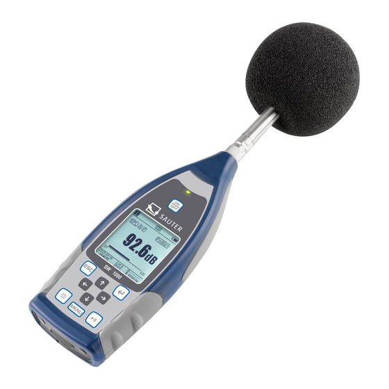
- Page 1 Sauter GmbH Ziegelei 1 Phone : +49-[0]7433- 9933-0 D-72336 Balingen Fax: +49-[0]7433-9933-149 e-mail: info@kern-sohn.com Internet: www.sauter.eu Instruction Manual Sound Level Meter SAUTER SW 1000 / SW 2000 Version 2.0 04/2020 PROFESSIONAL MEASURING SW-BA-e-2020...
-
Page 2: Table Of Contents
V. 2.0 08/2020 Instruction Manual Sound Level Meter Congratulations on purchasing a high-quality sound level meter from SAUTER. We wish you much pleasure with your quality measuring instrument and its complex range of functions. For questions, wishes or suggestions we are at your disposal. - Page 3 6.3 Calibration ............................46 6.4 Firmware Update ........................... 46 6.5 Warranty ............................48 Annex ......................49 Corrections for typical reflections from the housing of the sound level meter and sound scattering around the microphone ....................49 Correcting the Draft Shield in the Free Field ............... 50 Corrections of the electret microphone ................
-
Page 4: Introduction
1. Introduction 1.1 General description The new measuring instruments SW 1000/ SW 2000 are upgrades of a new generation of octave sound meters according to the market requirements for the basic instrument SW 1000/200, which meets the requirements of the IEC standard as well as the Chinese GB/T standard for 1/1 octave measuring instruments. -
Page 5: Functional Upgrades
⚫ Remote control connection RS-232 ⚫ Mini thermal printer for printing the measured data ⚫ Internal GPS module (option), support of GPS time 1.4 Functional upgrades ➢ ➢ Single chip high speed ARM with USB port implemented floating point unit ➢... - Page 6 calculated in parallel with different frequency/time weightings. Automatic measurement according to user-defined date and 24 h Measurement time settings and storage of history data Frequency weighting Parallel A, B, C, Z Time Weighting Parallel detection of F, S, I and Peak Sound 18 dB (A), 23 dB (C), 31 dB (Z) Sound 20 dB(A), 26 dB(C), 31 dB(Z) Internal noise 2...
-
Page 7: Information For Regular Tests
also be provided by an external DC power source (7 V - 14 V, 500 mA) and the USB port (5 V, 1 A). The integrated buffer battery has been calibrated at the factory for an error of < 26 s in 30 days (< 10 ppm, (25 ± 16) °C). -
Page 8: Parts List
1.8 Parts list Type Description Standard Sound pressure measuring device without SW 1000/2000 microphone ICCP preamplifier with TNC connection SW-A01/SW-A02 Class 1 (1000) or Class 2 (200) microphone Draft shield SW-A03 Windscreen 90 mm diameter for microphone 1/2 Micro SD card SW-A04 4G memory card for data storage Battery 4 alkaline batteries (LR6 / AA / AM3... -
Page 9: Keypad
2.1 Keypad The sound level meter has 10 keys: <power button>: Press this button for 2 seconds to switch on the sound pressure meter. If the sound pressure gauge is in stop status, press this button for 2 seconds to enter the power off dialog and then press <... -
Page 10: Microphone Connection
2.2 Microphone connection The TNC connector at the top of the sound pressure gauge is for connecting the microphone and preamplifier (microphone and preamplifier are usually mounted together in one housing). The TNC connector is a threaded coaxial connector. The SW 1000 measuring instrument is equipped with a class 1 microphone, the SW 2000 measuring instrument with a class 2 microphone: SW-BA-e-2020... -
Page 11: Draft Shield
SW-A01: Pre-polarized measuring microphone 1/2", class 1. sensitivity: 50 mV/Pa. Frequency range: 10 Hz to 20 kHz. Common housing with ICCP preamplifier, power supply 4 mA/24 V. SW-A02: Pre-polarized measuring microphone 1/2", class 2. sensitivity: 40 mV/Pa. Frequency range: 10 Hz to 12.5 kHz. Common housing with ICCP preamplifier, power supply 4 mA/24 V. - Page 12 PWR: Standard DC socket (diameter 2.1 mm) for power supply, can be connected to an external power supply unit 7 - 14 V, 500 mA. ☆Note : External voltages above 14 V can damage the sound pressure meter! Mini USB: Mini USB port for connecting to a computer in USB drive mode or modem mode, 4.4.10 USB Mode for more information.
-
Page 13: Battery
RS-232: The interface can be used as a standard RS-232 interface in remote mode and for connecting the thermal printer in printer mode. For further details, see 4.6.3 Printer 5th RS-232 data exchange protocol. TRIGGER: Trigger input with standard 3.5 mm headphone jack. For further details, please refer to 4.4.4 Trigger. -
Page 14: Gps
2.6 GPS The GPS antenna is located at the top of the sound pressure meters with GPS option. ☆ Note: Whether the GPS function is required must be known before delivery to the user, otherwise you must send the sound pressure meter to the factory to install the GPS module. -
Page 15: Measurement Screen
3. measurement screen The sound pressure meter has two measuring modes: level measurement and 1/1 octave measurement. The user can select the measurement in the Function menu. The level meter has 8 screens that can be switched with the arrow keys < ◄>, <►>. -
Page 16: Screen In Level Measurement Mode
Power-up status. The following icons are displayed from left to right: external power, battery power (with voltage indicator) and USB power. Measurement calculation mode Filter status Detector status Symbol of the profile. Displays the profile number of the current display. Measured value Visualization and display of the measured values in the current measuring range as a dynamic bar graph. - Page 17 LN Statistics Displays 10 groups with statistical results. Each data source group (fixed mode for SPL, filter and detector adjusted) percentage can be set in the menu. Time history Display of the current noise value and the time domain curve. The data sources (one of the 3 profiles) and the time domain curve (1 minute, 2 minutes and 10...
-
Page 18: Screen Of The 1/1-Octave Mode
GPS page 2. display the number of satellites for positioning signal-to-noise ratio of all visible satellites (0 dB - 99 dB). ☆ Note: The number of visible satellites may be greater than the number satellites positioning because some satellites are not available for positioning. -
Page 19: Operation And Setting Of The Menu
Octave table page 3. display of the measured data of LAeqLBeq, LCeq LZeq. lights red and appears when the data exceeds the threshold value. 4. operation and setting of the menu Press the <Menu> button to enter the next menu. All measurement parameters can be set in the menu. - Page 20 measurement should be used. The With calibration factor calibration procedure allows the user to manually adjust the calibration factor. 4.2.1 Calibration by measurement Select the By Measure option and press the <Enter> button to enter this menu. See Chapter 7 for more details on the specified calibrator and its corresponding adjustment values.
- Page 21 Then switch on the calibrator and set a constant sound level (for example 94 dB). SW-BA-e-2020...
-
Page 22: Measurement
Select Calibration from the menu and press <Enter> to enter the By Measurement menu. Set the value for Cal.Level in the menu, for example to 93.8 dB. Calibration is performed 5 seconds after pressing the <Start> button. When the calibration is finished, the sound pressure meter updates the calibration factor. - Page 23 4.3.1 Measurement setup The MEAS.setup menu is the most important menu for the measurement. Here you can set the parameters for delay, integration period, repeat, SW protocol step, SWN protocol step, CSD protocol and CSD protocol step. You can select options with the arrow keys <▲>, <▼>.
- Page 24 CSD Log.step (CSD log step) is the log step (the interval time) for saving the data as CSD file. Press <◄>, <►> to select the following option: 1s to 59s, 1min to 59min, 1h to 24h. Profile1 14 sets of Octave Profile2 Custom...
- Page 25 4.3.3 ICCP Power Supply The ICCP menu controls the power supply of all ICCP sensors via the 24 V/4 mA constant current source. Disable the ICCP power supply before connecting another sensor or connecting directly to the signal source. Press the arrow keys <◄>, <►> to select. 4.3.4 Profiles 1 to 3 The menu for the profiles 1 - 3 allows the definition of the filter, the detector, the mode and the storage options of SWN files.
- Page 26 4.3.7 Statistics The data source for the statistics is permanently set to SPL. The user cannot change this setting. However, the user can define the filter and detector for SPL and the statistics value using this menu. mode: The setting is permanently assigned to SPL and cannot be changed. Filter: You can define the filter for the statistical analysis with the arrow keys <◄>...
- Page 27 4.3.10 Adjustable measurements There are 14 adjustable measurement menu options where you can define the parameters for 1 - 14 adjustable measurements. Use the arrow keys <▲> , <▼> to select the option and press <Enter> to move to the next menu level. Use the arrow keys <▲>...
- Page 28 ☆Note : The repetition time must be greater than the total integral time (integral time x repetition) + 5 s, because a fixed delay of 3 s is set for the timer when measurement is triggered and 2 more seconds are required before the delay. You must not change the settings when the timer is running.
-
Page 29: Setup
4.3.12 24 h measurements with timer The user can use the timer to implement a 24-hour measurement. The following description uses an example to show how to implement the 24-hour measurement. Purpose: The measurement starts first on 14 March 2015 00:00 and measures the first 5 min of each hour. - Page 30 4.4.2 Backlighting The sound pressure meter automatically turns off the backlight to reduce power consumption and save battery life. In the Backlight menu, you can enable or disable the power off and change the delay time for the backlight. Press the arrow keys <▲> , <▼>...
- Page 31 With the arrow keys <▲> , <▼> you can select the date format and change the date. With the arrow keys <◄> , <►> you can select the year, month and day, and with the arrow keys <▲> , <▼> you can modify their value. Press <Enter> to save the setting.
- Page 32 C and 41 °C, i.e. at room temperature. The real RTC error can be greater than the value specified in the user manual if the temperature range is exceeded. 4.4.6 Automatic switch-off The sound level meter has an automatic switch-off function to reduce power consumption.
- Page 33 4.4.7 RS-232 interface The RS-232 interface menu is used to set the options for the serial connection, see 5. RS-232 data exchange protocol. Mode of the RS-232 interface: RS-232 remote option, printer. Use the arrow keys <◄> , <►> to select. The sound level meter can send and control data via the RS-232 port in remote mode.
- Page 34 In the OCT File menu, you can delete the OCT file. The operation is the same as in the SWN file menu. The CSD File menu allows you to delete, display and print the CSD file. You can move the cursor between Select and Option using the arrow keys <▲>...
- Page 35 4.4.9 Boot mode In Start mode, use the arrow keys <▲>, <▼> to select Normal, Power & Boot, and Boot & Auto Meas. (Switch on and Auto Meas.). ☆Note : The switch for the hardware mode in the battery compartment must be set according to the start mode. Normal: You must set the hardware switch for the mode to Normal.
- Page 36 4.4.10 USB mode The USB Mode menu allows you to set the working mode when you connect the sound level meter to the computer with a USB cable. Always Ask, USB Disk Mode (USB drive) and Modem Mode are available for selection. Always Ask: The device always asks back which mode to select when connecting the USB cable to the computer.
-
Page 37: Language
4.4.12 Setup template The setup template allows you to save five user group setting parameters of the sound level meter for different applications. ☆Note : The template does not change the calibration factor. Do not try to load the template of the old version into the firmware of the new version, because certain modifications of the template format may be present. - Page 38 4.6.1 AC OUT (alternating voltage output) There are two analog outputs on the sound level meter: DC output and AC output. Connect the DC output or AC output to the other device or system using coaxial cables. The input impedance of the termination device or system should be approximately 5 kΩ.
-
Page 39: Factory Settings
If the user selects the Manual option, the user must click Print Now and press the <Enter> key to print the measurement data. ☆Note : Switch to the Printer mode in the RS-232 menu before you start printing. 4.7 Factory settings Factory settings offer the possibility to reset all parameters that have been changed by the users to the factory settings. -
Page 40: Transmission Protocol
5.2 Transmission protocol The RS-232 interface protocol for SW 1000/200 is based on a blockwise transmission according to the following pattern A typical command block or response block consists of a start character, the ID, the attribute character, the command or data, the end character, the block check character, the carriage return and carriage return characters, as shown in the following figure: <STX>... - Page 41 Name Meaning ‘C’ Command block ‘A’ Answer block <ACK> Normal response <NAK> Error response 5.2.4 BCC (block check character) The block check character bit in the block is calculated by the sender. The receiver then calculates the BCC value of the block and compares it to the BCC value in the sender block.
- Page 42 The error code occupies 4 bytes. All possible error codes are listed in the following table See section 5.2.6 for the meaning of the error codes Error code Meaning 0001H Instruction errors 0002H Parameter error 0003H Not available in current status 5.2.6 Recovery after transmission errors Various errors can occur during transmission of the command block or response block.
- Page 43 (4) Parameter error Parameters in the command block may also be incorrect because parameters are not separated by a space, exceed the available range, or have an incorrect number of arguments. When the above error occurs, the sound level meter returns a NAK block containing the error code 0002H.
-
Page 44: Instructions
5.2.9 Nominal parameters Nominal Name Min. Max. Description value value exceeded, Response time of the — — seco processing should work on time sound level meter overflow. Time interval of the — — — instruction to send to 100 ms the sound level meter Waiting time for the This means that the sound level... -
Page 45: Operating Instructions
Return information Error response: — Query ► statement Sound level- Computer Measuring device Return 6. operating instructions 6.1 Operation ⚫ Minimize the influence of vibrations when using the sound level meter. Mechanical vibrations can affect the display levels in the lower frequency range of the sound level meter (10 Hz to 20 kHz). -
Page 46: Common Problems And Solutions
6.2 Common problems and solutions Problem Possible cause and solution ⚫ Battery exhausted: Replace the battery. ⚫ Power supply failure: Replace the power supply. Device cannot be started. ⚫ Power switch does not work: Return the device to the factory. Incorrect measurements: Try to recalibrate the device. - Page 47 After installing the driver, connect the sound level meter to the computer with a USB cable. In the Device Manager, you will find a new device called Silicon Labs CP210x USB to UART Bridge (COMx). ☆Note : Supply the sound level meter with an external power source when connecting it to the computer.
-
Page 48: Warranty
Step 4: First press the button in the upper right corner to select the firmware and then press the Update button start the program. The whole procedure takes 3 to 4 minutes. ☆Note : Reset the device to the factory settings and perform the calibration at least once after the firmware update, otherwise the sound level meter may not work properly. -
Page 49: Annex
7. Annex 7.1 Corrections for typical reflections from the housing of the sound level meter and sound scattering around the microphone Corrections for typical reflections from the housing of the sound pressure meter and sound scattering around the microphone -0,5 -1,0 -1,5 Freq. -
Page 50: Correcting The Draft Shield In The Free Field
7.2 Correcting the Draft Shield in the Free Field Correcting the Draft Shield in the open field -0,5 -1,0 -1,5 -2,0 Note: The frequency marked with * is not prescribed in the standard, the exact frequency can be found in IEC 61672-1. Freq. -
Page 51: Corrections Of The Electret Microphone
7.3 Corrections of the electret microphone The following corrections are measured by the electret microphone and the power supply. Corrections of the electret microphone 10,0 Freq. [Hz] Value [dB] Freq. [Hz] Value [dB] Freq. [Hz] Value [dB] Freq. [Hz] Value [dB] 0,000 0,043 2000... -
Page 52: Typical Frequency Response And Corresponding Upper Limit
7.4 Typical frequency response and corresponding upper limit Each microphone has been carefully tested at the factory before delivery. The calibration diagram in the enclosed box shows the real frequency response of the electret microphone and the frequency response in free field. The typical frequency response with frequency weighting of the sound level meter is shown in the following figure. -
Page 53: Technical Data Of The 1/1 Octave Filter
7.5 Technical data of the 1/1 octave filter The 1/1 octave filter was developed from a Butterworth filter with base 10. The technical specifications of each filter are shown in the figure below. 31.5Hz~500Hz octave filter 10,0 -10,0 -20,0 -30,0 -40,0 -50,0 -60,0... - Page 54 ⚫ LEQ1: The time average sound level or an equivalent continuous sound level. The 10-fold logarithm to base 10 of the ratio of the square of the average time of a frequency weighted sound pressure signal during a specified time interval and the square of the reference value LEQ is the current integral value of the sound level at the specified duration.
Need help?
Do you have a question about the KERN SW 1000 and is the answer not in the manual?
Questions and answers