Table of Contents

Related Manuals for NEC NovaScale R480 E1


Summary of Contents for NEC NovaScale R480 E1
- Page 1 NovaScale R480 E1 ■ ■ ■ ■ ■ ■ ■ ■ ■ ■ ■ ■ ■ ■ ■ ■ ■ ■ ■ ■ ■ ■ ■ ■ ■ ■ ■ ■ ■ ■ ■ ■ ■ ■ ■ ■ ■...
- Page 2 The information disclosed in this document, including all designs and related materials, is the valuable property of NEC Computers and/or its licensors. NEC Computers and/ or its licensors, as appropriate, reserve all patent, copyright and other proprietary rights to this document, including all design, manufacturing, reproduction, use, and sales rights thereto, except to the extent said rights are expressly granted to others.
-
Page 3: Table Of Contents
Memory Mirroring Feature ....................2-14 System Cooling........................2-15 System Board Features ......................2-15 Security ..........................2-18 EXPRESSBUILDER ......................2-19 NEC ESMPRO ........................2-20 Maintenance Tools ......................... 2-20 System Diagnostic Utility ...................... 2-20 NEC DianaScope ........................2-20 Using Your Server ........................2-21 Front Bezel.......................... - Page 4 Setup Flow ........................... 3-2 Selecting a Site ..........................3-3 Installing or Removing the Server into/from the Rack ............3-6 Checking Components ......................3-7 Required Tools ......................... 3-7 Installation Procedure ......................3-8 Removal Procedure........................ 3-15 Connecting Peripheral Devices ....................3-17 Connecting the Power Cord ....................... 3-19 Turning On the Server ........................
- Page 5 NEC ESMPRO........................... 6-15 Functions and Features ......................6-15 NEC DianaScope........................6-16 Universal RAID Utility ......................6-17 Setup with Express Setup....................... 6-17 Manual Setup ......................... 6-17 Using the Universal RAID Utility via the Network ............... 6-17 Chapter 7 ........................... 7-1 Maintenance ........................7-1 Making Backup Copies ........................
- Page 6 Memory Dump ........................... 8-57 Preparing for Memory Dumping.................... 8-57 Saving the Dump File ......................8-58 Recovery for Windows Server 2003 x64 Editions and Windows Server 2003 ......8-58 Remote Management Feature..................... 8-59 Changing the Management LAN Settings ................8-59 Resetting the Server ........................8-60 Forced Shutdown........................
- Page 7 About the System Partition Size ..................... D-2 Installing Windows Server 2003 x64 Editions ................D-3 Creating "Windows Server 2003 x64 Edition OEM-Disk for EXPRESSBUILDER" .... D-3 Windows Server 2003 x64 Editions Clean Installation............D-5 Updating the System - Applying Service Pack - ..............D-7 Driver Installation and Advanced Settings ................
- Page 8 Keep this User’s Guide at hand for quick reference at anytime necessary. SAFETY INDICATIONS Follow the instructions in this User’s Guide for your safety to use the server. The server contains components with possible danger and hazards that may caused by ignoring warnings. Preventive actions can be taken against such hazards.
- Page 9 SYMBOLS USED IN THIS USER'S GUIDE AND WARNING LABELS Attentions Indicates that improper use may cause an electric shock. Indicates that improper use may cause personal injury. Indicates that improper use may cause fingers to be caught. Indicates that improper use may cause the clip of a hand. Indicates that improper use may cause fumes or fire.
- Page 10 SAFETY INDICATIONS BY COLOR OF THE PARTS Only green areas are available for hot swap or hot plug operation. To avoid electric shock, disconnect all AC cords before accessing to other parts especially blue area inside the system. NOTE: This equipment has been tested and found to comply with the limits for a Class A digital device, pursuant to Part 15 of the FCC Rules.
- Page 11 AC uninterruptible power supply (UPS) unit should be used. Notes: (1) No part of this manual may be reproduced in any form without the prior written permission of NEC Corporation. (2) The contents of this User's Guide may be revised without prior notice.
- Page 12 Welcome to the NovaScale R480 E1 server. The NovaScale R480 E1 server holds powerful performance and employs the latest technology to implement a computer for the next generation. With its potential capabilities, the server may be used as the workstation PC that configures a client-server system and provides high-speed processing and superior reliability.
- Page 13 ABOUT THIS USER'S GUIDE This User’s Guide is a guide for proper setup and use of the server. This User’s Guide also covers useful procedures for dealing with difficulties and problems that may arise during setup or operation of the server. Keep this manual for future use. The following describes how to proceed with this User’s Guide.
- Page 14 Appendix C IRQ and I/O Port Address provides a list of factory-set IRQs and I/O port addresses assigned. Appendix D Installing Windows Server 2003 x64 Editions describes how to install Microsoft Windows Server 2003 x64 Editions without using Express Setup. Using the Express Setup tool is recommended for installing Windows Server 2003 x64 Editions.
-
Page 15: Chapter 1
Chapter 1 Notes on Using Your Server This chapter includes the information necessary for the proper and safe operation of your server. -
Page 16: Warning Labels
WARNING LABELS A warning label is attached to the potentially dangerous components or their vicinity in your server to inform the user that a hazardous situation may arise when operating the server. (Do not intentionally remove or damage any of the labels.) If you find any labels totally/partially removed or illegible due to damage, contact your sales representative. -
Page 17: Safety Notes
SAFETY NOTES This section provides notes on using your server safely. Read this section carefully to ensure proper and safe use of the server. For symbols, see "SAFETY INDICATIONS" provided earlier. For part names described in the safety instruction chapter in this guide, refer to "Features and Controls" in Chapter 2. General WARNING Do not use the server for services where critical high availability may directly... -
Page 18: Notes On Installing And Accessing The Rack Cabinet
Notes on Installing and Accessing the Rack Cabinet CAUTION Do not carry or install the rack cabinet only by a single person. More than one person is required to carry or install the rack. Failure to follow this instruction may cause the rack to fall, resulting in personal injuries and/or surrounding devices to be broken. -
Page 19: Power Supply And Power Cord Use
Power Supply and Power Cord Use WARNING Do not hold the power plug with a wet hand. Do not disconnect/connect the plug if your hands are wet. Failure to follow this warning may cause an electric shock. CAUTION Plug in to a proper power source. Use a grounded wall outlet of the specified voltage. -
Page 20: Installation, Relocation, Storage, And Connection
Installation, Relocation, Storage, and Connection CAUTION Never attempt to lift the server only by yourself. Your server weighs 47 kg (depending on its hardware configuration). Carrying the server only by yourself may strain your back. Hold the server firmly by its bottom with at least three persons to carry it. - Page 21 CAUTION Do not connect any interface cable with the power cord of the server plugged to a power source. Make sure to power off the server and unplug the power cord from the power outlet before installing/removing any optional internal device or connecting/disconnecting any interface cable to/from the server.
-
Page 22: Cleaning And Working With Internal Devices
Cleaning and Working with Internal Devices WARNING Do not disassemble, repair, or alter the server. Never attempt to disassemble, repair, or alter the server on any occasion other than the ones described in this manual. Failure to follow this instruction may cause an electric shock or fire, as well as malfunctions of the server. -
Page 23: During Operation
During Operation CAUTION Avoid contact with the server during thunderstorms. Disconnect all the power plugs from the outlet when a thunderstorm is approaching. If it starts thundering before you disconnect the all power plugs, do not touch any part of the server including the cables. Failure to follow this warning may cause a fire or an electric shock. -
Page 24: For Proper Operation
FOR PROPER OPERATION Observe the following notes for successful operation of the server. Using the server while ignoring the notes will cause malfunctions or failures of the server. Install the server in a place that meets the requirements for successful operation. For more information, see Chapter 3, "Setting Up Your Server."... -
Page 25: Third Party Transfer
THIRD PARTY TRANSFER The following must be observed when you transfer (or sell) the server or software provided with the server to a third party: Server Make sure to provide this manual along with the server to a third party. IMPORTANT: About data on the hard disk drive Be sure to take appropriate measures not to leak important data (e.g., customers'... -
Page 26: Consumables
CONSUMABLES Your server contains some components that are only good for a limited period of time and require replacement, such as batteries, fans, the internal CD-RW/DVD-ROM drive, the floppy disk drive, and the mouse. For stable operation of the server, we recommend you replace these components on a regular basis. Ask your service representative for replacement or more information on the product lifespan. - Page 27 WARNING Do not remove the lithium and NiMH batteries. Your server contains lithium and NiMH batteries. Do not remove the battery. There is a danger of explosion if the battery is incorrectly replaced. Placing the lithium or NiMH battery close to a fire or in the water may cause an explosion. When the server does not operate appropriately due to the failure of lithium and NiMH batteries, contact your service representative to replace only with the same or equivalent type recommended by the manufacturer.
-
Page 28: User Support
USER SUPPORT When the server requires after-sales service, check if the warranty is still valid, and determine which service is necessary as indicated on the "Certificate". Before Asking for Repair, do the following when the server appears to fail: Check if the power cord and the cables to other devices are properly connected. See Chapter 8 to find if your problem fits one of the descriptions. - Page 29 Advice for Health The longer you keep using the computer equipment, the more you become tired, which may cause disorders of your body. When you use a computer, observe the following to keep yourself from getting tired: Good Working Posture Your working posture is good if the following are satisfied when you use a computer: •...
-
Page 30: Chapter 2
Chapter 2 General Description This chapter provides information that you should be familiar with before using the server. It includes names and functions of the components and features of the server. -
Page 31: Overview
OVERVIEW Your server is a highly reliable, high-powered, fault-tolerant, high-capacity, multiprocessing server based on the Quad-Core Intel® Xeon® Processor 7300 series or Dual-Core Intel® Xeon® Processor 7200 series. It is a solid performer and offers the latest technology. The combination of computng performance, memory capacity, and integrated I/O provides a high performance environment for many server market applications. -
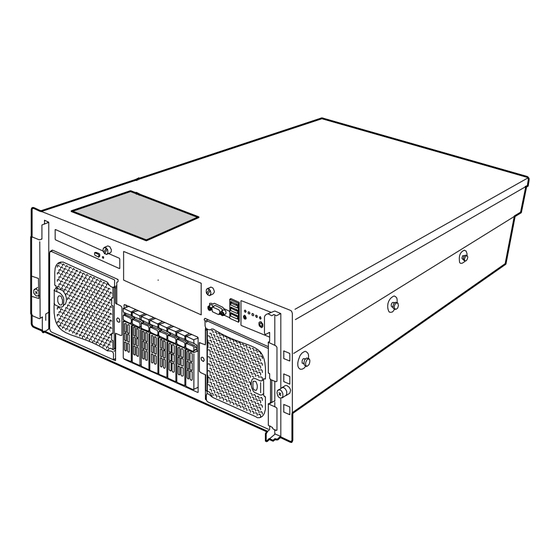
Page 32: Top View
Top View Top cover Open the top cover to install or remove optional memory boards, DIMMs, PCI boards, and fans. -
Page 33: Front View
Front View LEDs (See Chapter 8 for details.) Key hole Insert the security key to lock/unlock the front bezel Front bezel Open the front bezel to access the POWER/SLEEP switch, 5.25-inch device (option), or CD-RW/DVD-ROM drive, or to install or remove the USB floppy disk drive, hard disk drive, processor, memory board, DIMM, PCI board, and fan. -
Page 34: Front View (With Front Bezel Removed)
Front View (with Front Bezel Removed) Refer to Chapter 8 for more information on the LEDs indications. 1-1 1-2 1-3 7-0 7-1 7-2 7-3 7-4 7-5 7-6 7-7 CD-RW/DVD-ROM drive The CD-RW/DVD-ROM drive reads data from the inserted CD/DVD-ROM. 1-1: Access LED (lights orange during the access) 1-2: CD/DVD tray eject button 1-3: Emergency hole 5-inch device bay... -
Page 35: Front View (Switches And Leds)
Front View (Switches and LEDs) Refer to Chapter 8 for more information on the LEDs indications. RESET switch Press this switch to reset the server. DISK Access LED LAN1/2 access LED LAN3/4 access LED STATUS LED POWER/SLEEP LED UID (Unit ID) LED UID (Unit ID) switch Use this switch to turn on or off the ID LED located on the front and rear panels of the server. -
Page 36: Rear View
Rear View Refer to Chapter 8 for more information on the LEDs indications. 4 5-4 5-3 11-1 11-2 11-3 11-1 11-2 11-3 12-1 12-2 PCI Express slot (#1 to #7 from left) Slots 1 and 2: Hot-plug PCI Express (x8) Slots 3 and 4: Non-hot-plug PCI Express (x8) Slots 5, 6, and 7: Non-hot-plug PCI Express (x4) (Can contain x8 board.) Keyboard connector... -
Page 37: Internal View
Internal View 5-inch device bay Memory board Rear fan bay Non-hot-plug PCI slot Hot-plug PCI slot... -
Page 38: Base Board
Base Board 2-B 2-A 16-1 16-2 16-3 1-4 1-3 2-C 10 Rear fan connector The last digit represents the port number. Memory board connector The last digit represents the port number. Front panel connector Power BP interface connector Power connector Processor socket The last digit represents the port number. -
Page 39: Memory Board
Memory Board DIMM slot (The last digit represents the slot number.) I/O Riser Board Mouse connector Keyboard connector Management LAN connector LAN connector #4 LAN connector #3 Baseboard interface connector 2-10... -
Page 40: Sas Riser Board
SAS Riser Board FRONT REAR SAS port A SAS port B DIMM connector for RAID RAID activation key Ni-MH battery for RAID 2-11... -
Page 41: Standard Features
SETUP (BIOS setup utility) Security feature (security lock) RAID Configuration Utility Redundant power supply (for 200 to 240 VAC power or partially for 100 to Management Utilities 120 VAC) NEC ESMPRO RAID system (Onboard RAID NEC DianaScope Controller) Remote Management Feature 2-12... -
Page 42: Power Supplies
Power Supplies The server can continue its operation without interruption even if a single power supply unit fails (power redundant configuration). In addition, if the AC power of each power supply unit is divided into two lines, the server can continue its operation without power interruption even if one of the AC power line fails (AC power redundant configuration). -
Page 43: Memory Mirroring Feature
The following indicates that the memory mirroring feature is in use: a) The failing DIMM group is degraded when the server restarts. b) If the NEC ESMPRO Agent has been installed, the following log is registered as a system log of Event Viewer:... -
Page 44: System Cooling
System Cooling The chassis top cover must be installed for proper system cooling. Cooling components must be hot-swapped within two minutes. This time period applies only to the time that the cooling component is physically removed, not from the time of failure. The cooling subsystem consists of hot-swap, redundant (7+1) fans. - Page 45 LSI MegaRAID™ SAS PCI EXPRESS™ ROMB The SAS riser card includes the LSI MegaRAID™ SAS PCI EXPRESS™ ROMB (called "On Board RAID (MegaRAID ROMB)" hereafter) The On Board RAID (MegaRAID ROMB) supports the following features: Dual-channel SAS interface (CH0 and CH1) Connect the HDD cage to CH0 and CH1.
- Page 46 Remote Management The server may be monitored and managed via LAN/WAN by using EXPRESSSCOPE Engine 2 and the NEC DianaScope utility stored in the EXPRESSBUILDER DVD. The EXPRESSSCOPE Engine 2 uses the BMC (Baseboard Management Controller) as a system management LSI.
-
Page 47: Security
power linkage feature that enables control over the power supply from the UPS to the server. AC-LINK feature can be enabled or disabled with "AC-LINK" in the Server menu of the BIOS setup utility, "SETUP." (See Chapter 4.) Security To help prevent unauthorized entry or use of the system, the system includes a full lockable front panel and a Server Management software that monitors the system intrusion switches. -
Page 48: Expressbuilder
EXPRESSBUILDER The EXPRESSBUILDER helps you install the Operating System, the Management software or use the maintenance utilities. Refer to Chapter 6 for details. The functions of the EXPRESSBUILDER are: To install the Operating System. "Express Setup" helps you install the Windows. (See Chapter 5.) To diagnose the system. -
Page 49: Nec Esmpro
The NEC DianaScope is a software for the remote management of the server. The NEC DianaScope can control the managed server even if the OS is not running on the managed server. See Chapter 6 and online document in the EXPRESSBUILDER. -
Page 50: Using Your Server
USING YOUR SERVER This section describes basic operations of your server, including how to use devices such as the CD-RW/DVD-ROM drive. See Appendix B for notes on using DVD/CD-ROM, and accessories including the keyboard and the mouse. Front Bezel Remove the front bezel to power on/off the server, to access the CD-RW/DVD-ROM drive, and to install/remove hard disk drives to/from the 2.5-inch hard disk drive bay. -
Page 51: Power/Sleep Switch
POWER/SLEEP Switch Use the POWER/SLEEP switch to turn on/off the server. Power On Press the POWER/SLEEP switch on the front of the computer chassis. The POWER/SLEEP LED lights in green. POWER/SLEEP LED POWER/SLEEP switch IMPORTANT: If the power cord is connected to a power control device such as a UPS (Uninterruptive Power Supply), make sure that the power control device is powered. -
Page 52: Post
POST The POST (Power On Self-Test) is the self-diagnosis feature saved in the base board of the server. When the power of the server is turned on, the POST automatically runs to check the base board, I/O riser board, memory board, processor, keyboard, and mouse. During the POST, messages indicating that several BIOS setup utilities are started may also appear. - Page 53 LSI MegaRAID SAS-MFI BIOS Version XXXX (Build MMM DD, YYYY) Copyright (c) 2007 LSI Logic Corporation HA -X (Bus X Dev X) MegaRAID SAS PCI Express(TM) ROMB FW package: X.X.X-XXXX X Logical Drive(s) found on the host adapter. X Logical Drive(s) handled by BIOS Press <Ctrl>...
-
Page 54: Post Error Messages
NOTE: The operation or utility to be started at each key entry is described below. These operations or utilities may not always be started. Press F2 to start the BIOS setup utility. Start the utility to change the settings of the server in order to fit the environment in which the server is used. -
Page 55: Floppy Disk Drive
Floppy Disk Drive Your server is not equipped with a floppy disk drive. Use the optional USB floppy disk drive if necessary. CD-RW/DVD-ROM Drive Your server is equipped with a CD-RW/DVD-ROM drive on its front to read data from a CD/DVD-ROM. The CD/DVD-ROM provides larger and faster data read than the floppy disk. - Page 56 Press the CD/DVD tray eject button or push the front of the tray lightly to retract it into the drive. IMPORTANT: If a noisy sound is emitted by the CD-RW/DVD-ROM drive after setting a CD/DVD-ROM, and set it again correctly. To take out the media from the CD-RW/DVD-ROM drive, press the CD/DVD tray eject button to eject the tray.
- Page 57 IMPORTANT: Do not use a toothpick or a plastic stick that could break easily. If the above procedure does not let you take out the CD/DVD-ROM, contact your service representative. Hold the tray and pull it out. Take out the CD/DVD-ROM. Push the tray back into position.
-
Page 58: Chapter 3
Chapter 3 Setting Up Your Server This chapter describes how to set up your server appropriately for your system, on a step-by-step basis. -
Page 59: Setup Flow
SETUP FLOW Follow the flowchart below to set up the server. Selecting a site Select a suitable site for the server. Unpacking the system Unpack the server and accessories from the shipping carton box. Assembling the rack-mount system Assemble the 19-inch rack cabinet and install the server. Connecting the peripheral devices Connect the peripheral devices to the server. -
Page 60: Selecting A Site
SELECTING A SITE Your server unit should be mounted in a standard EIA 19-inch rack cabinet. Refer to the documentation attached to the rack or contact your service representative for the installation of the rack. WARNING Observe the following instructions to use the server safely. Failure to follow these instructions may result in death or serious personal injury. - Page 61 The following figure illustrates a site suitable for installing the rack cabinet. * We recommend that the server should be used in a room where temperature is in the range between 15 to 25ºC. Room that satisfies the following conditions for 100 to 120 Vac/200 to 240 Vac operation: * parallel bi-polar wall power...
- Page 62 Do not install the rack in the places listed below. Not doing so may cause some malfunctions to occur. Do not: Locate the rack in a narrow space that would prevent devices from being pulled out from the rack completely. Locate the rack on a floor that cannot bear the total weight of the rack and devices mounted in the rack.
-
Page 63: Installing Or Removing The Server Into/From The Rack
Installing or Removing the Server into/from the Rack This subsection provides the instructions necessary ton install the rack-mount server unit into a standard EIA 19-inch rack cabinet. This subsection also describes the removal procedure for the rack mount server unit from the 19-inch rack cabinet. WARNING Observe the following instructions to use the server safely. -
Page 64: Checking Components
Checking Components Confirm that the following tools or components are provided before attempting the installation. Item Q'ty Remarks Front bezel Slide rail assembly (L) "L" is stamped on the rail. Slide rail assembly (R) "R" is stamped on the rail. Cable arm Arm stopper Tie-wrap... -
Page 65: Installation Procedure
Installation Procedure Install the server on the rack as described in the following procedure. Define the position (height) at which the server is to be installed. The server is 4U high. The bottom of the rail aligns with the bottom of server. Template (Front) Template (Rear) Make sure that the black lever surely locks the components. - Page 66 The front and rear supports of the rack have rectangular holes for screw fastening. For the NEC rack, round stamps are provided in 1U. As shown in the figure, a stamp must be positioned at the tip of slide rail assembly (lower side).
- Page 67 Secure the left and right sides of the slide rail assembly (for the rear side of the rack), with two screws (A). NOTES: Make sure that the frame tips on the slide rail assembly are squarely aligned with the rectangular hole frames of the rack and that the four screw holes of the rail can be seen through the mating rectangular holes of the rack.
- Page 68 Hold the server by three or more persons to mount it on the rack. CAUTION Observe the following instructions to use the server safely. Failure to follow these instructions may cause a fire, personal injury, or property damage. See pages 1-3 to 1-8 for details. Do not lift the server only by two or less persons.
- Page 69 Install the cable arm to the inner rail (to the right side viewed from rear of the server). NOTE: Install the cable arm so that its protrusions align with holes on the inner rail. Install the other side of the cable arm to the outer rail. 3-12...
- Page 70 NOTE: When installing the server into an NEC rack, fix the arm stopper to the slide rail assembly with screw (B). Viewed from inside Push the arm stopper in the direction shown Arm stopper by the arrow mark so that the folded portion hits the end, then fix it with the screw.
- Page 71 Screws Install the front bezel. The installation is completed. 3-14...
-
Page 72: Removal Procedure
Removal Procedure Do not remove the server from the rack by yourself. CAUTION Observe the following instructions to use the server safely. Failure to follow these instructions may result in death or serious personal injury. See pages 1-3 to 1-8 for details. Do not lift the server only by two or less persons. - Page 73 Push the left and right release levers to release the lock and then pull out the server from the rail slowly. Release lever IMPORTANT: Push each release lever using a screwdriver or a similar tool. Do not use your fingers, which could get caught, causing severe injuries.
-
Page 74: Connecting Peripheral Devices
CONNECTING PERIPHERAL DEVICES Connect peripheral devices to the server. The server is provided with connectors for wide variety of peripheral devices on its front and rear. The figure on the next page illustrates the available peripheral devices for the server in the standard configuration and the locations of the connectors for the devices. - Page 75 FRONT Device with a USB interface (e.g., keyboard) REAR Mouse Keyboard (multiport repeater) Management PC 100BASE-TX / 10BASE-T Device with a USB Hub (multiport repeater) Network system interface (USB2.0) 1000BASE-T / on LAN (e.g., keyboard) 100BASE-TX / (connected via a 10BASE-T hub) Device with a serial...
-
Page 76: Connecting The Power Cord
CONNECTING THE POWER CORD Connect the provided power cord to the server. WARNING Observe the following instructions to use the server safely. Failure to follow these instructions may result in death or serious personal injury. See pages 1-3 to 1-8 for details. Do not hold the power plug with a wet hand. - Page 77 To connect the power cord from the server to an uninterruptible power supply (UPS), use the service outlets on the rear of the UPS. Refer to the manual that comes with the UPS for more information. Connector for TVSS device Outlet socket Input breaker Option slot...
-
Page 78: Turning On The Server
TURNING ON THE SERVER Turn on the server and follow the on-screen instructions. IMPORTANT: Before turning on the server: Some optional boards require additional setup with the SETUP utility before installation. If the server has a PCI board with the PCI-to-PCI bridge installed, the SETUP utility cannot be started. - Page 79 The POWER/SLEEP LED on the front of the server lights up. After a few seconds, a full screen logo appears on the screen and the Power On Self-Test (POST) begins. The POST runs automatically when you power on the server or reset it using a key combination (Ctrl + Alt + Delete).
-
Page 80: Installing The Operating System
INSTALLING THE OPERATING SYSTEM See Chapter 5 for more information on the Operating system installation. IMPORTANT: Before installing the operating system, adjust the system date and time using the BIOS setup utility "SETUP". See Chapter 4 detail. INSTALLING THE UTILITIES Install the utilities included with the server. -
Page 81: Chapter 4
Chapter 4 Configuring Your Server This chapter describes the Basic Input Output System (BIOS) configuration. When you install the server for the first time or install/remove optional devices, thoroughly read this chapter for a better understanding of the settings. SYSTEM BIOS ~ SETUP ~ The SETUP utility is provided to make the basic hardware configuration for the server. -
Page 82: Starting The Setup Utility
Starting the SETUP Utility To run the SETUP utility, perform the following procedures: Turn on the power of the server. A full-screen logo appears on the screen (the POST screen may appear instead, depending on the corresponding BIOS setting). After a while, one of the following messages appears at the bottom of the screen. Pattern 1: Press <F2>... -
Page 83: Description On On-Screen Items And Key Usage
Description on On-Screen Items and Key Usage Use the following keyboard keys to work with the SETUP utility. (Key functions are also listed at the bottom of the screen.) Indicates the current menu. Setup item menu Online help Indicates there window are submenus. -
Page 84: Configuration Examples
To link with the temperature monitoring feature of NEC ESMPRO Agent Select [Server] - [Thermal Sensor] - [Enabled]. To control the power supply of the server with NEC ESMPRO Manager via the network Select [Advanced] - [Advanced Chipset Control] - [Wake On Lan/PME] - [Enabled]. - Page 85 Memory To enable the memory degradation feature Select [Advanced] - [Memory/Processor Error] - [Halt]. To check the installed memory (DIMM board) status Select [Advanced] - [Memory Configuration] and check the status indications. The on-screen DIMM socket locations and on the memory board are associated as shown in the following figure.
- Page 86 Processor To enable the processor degradation feature Select [Advanced] - [Memory/Processor Error] - [Halt]. To check the installed processor status Select [Main] - [Processor Settings] and check the status indications. The on-screen processor numbers and the socket locations on the base board are associated as shown in the following figure.
- Page 87 Security To set BIOS passwords Select [Security] - [Set Supervisor Password] and enter a password. The Supervisor password and User password can be set separately, and only the User password is restricted when accessing the SETUP utility. To enable/disable the POWER/SLEEP switch and SLEEP switch Disabling Select [Security] - [Power Switch Inhibit] - [Enabled].
- Page 88 PCI Hot Plug To install the PCI board with the PCI hot plug Select [Advanced] - [PCI Configuration] - [Hot Plug PCI Control] - [Minimum/Middle/Maximum*] * The setting varies depending on the PCI board. See the table below. Board name Setting Value 1000Base-T Adapter (2ch) Minimum...
-
Page 89: Menus And Parameters Descriptions
Menus and Parameters Descriptions The SETUP utility includes the following six major menus: Main Advanced Security Server Boot Exit To set minute functions, select a submenu from the above menus. The following describes the available functions and parameters, as well as the factory-setting for each menu. Main After entering SETUP, the Main menu appears first. - Page 90 Processor Settings Selecting "Processor Settings" on the Main menu shows the following submenu. See the table below for the items. Option Parameter Description Your Setting Processor [No] Clears the error information on the processor. Retest Processor – Indicates the frequency of the processor. Speed Setting Processor 1-4 –...
- Page 91 Option Parameter Description Your Setting Virtualization [Enabled] This menu appears only when the processor Technology supports Intel® Virtualization Technology. Disabled Specify whether the Intel® Virtualization Technology is enabled or disabled. If the parameter is changed, the DC power of the system must be turned off.
- Page 92 Advanced The Advanced menu appears if you move the cursor to "Advanced." ) and press Enter. To display a submenu, position the cursor on a selection that has a submenu (preceded by symbol See the table below for the items. Option Parameter Description...
- Page 93 Memory Configuration Selecting "Memory Configuration" on the Advanced menu displays the following screen. See the table below for the items. Option Parameter Description Your Setting Installed – Indicates the mounted memory capacity memory (Display only). Available – Indicates the capacity of memory available in under 4GB the area smaller than 4GB.
- Page 94 Memory Riser Board x Selecting "Memory Riser Board x (A to D)" on the Memory Configuration menu displays the following submenu. See the table below for the items. Option Parameter Description Your Setting DIMM #1 - 8 Normal Indicates the current memory status for each Status Not Installed memory board.
- Page 95 PCI Configuration Selecting "PCI Configuration" on the Advanced menu displays the following screen. Selecting an item on the screen allows the proper submenu to appear. See the table below for the items. Option Parameter Description Your Setting PCI Slot 1-7 [Enabled] Disables/enables the Option ROM BIOS Option ROM...
- Page 96 Hot-plug PCI Control Selecting "Hot-plug PCI Control" on the PCI Configuration submenu displays the following screen. See the table below for the items. Option Parameter Description Your Setting Reserving [Disabled] Determines memory space at every memory space for empty slot for PHP (PCI Hot-plug). Minimum Reserved memory space is: Middle...
- Page 97 Onboard SAS/Onboard NIC/Onboard Video Selecting "Onboard SAS", "Onboard NIC", or "Onboard Video" on the PCI Configuration submenu displays a screen similar to the one shown below. (Shown below is the one when Onboard SAS is selected.) See the table blow for the items. Option Parameter Description...
- Page 98 Peripheral Configuration Selecting "Peripheral Configuration" on the Advanced menu displays the following screen. See the table below for the items. IMPORTANT: Note that the interrupt and/or base I/O address cannot overlap with others. If the value set for the interrupt or base I/O address is used for another resource, the yellow asterisk (*) appears.
- Page 99 Option Parameter Description Your Setting Serial Port A Disabled Specifies whether the serial port A is enabled or disabled. [Enabled] Base I/O Address [3F8] Selects the base address and interrupt (IRQ) for serial port A. These menus are displayed only when the Serial port A is enabled.
- Page 100 Advanced Chipset Control Selecting "Advanced Chipset Control" on the Advanced menu displays the following screen. Positioning the cursor on a and pressing Enter displays the corresponding submenu. menu (item preceded by symbol " ") See the table below for the items. Option Parameter Description...
- Page 101 Security Positioning the cursor to "Security" shows the following screen. On the Security menu, register the Supervisor password first, then the User password. When the User password is registered, you can access all the menu items. Selectable only when User Password is registered If you press Enter on "Set Supervisor Password", a screen similar to the one shown below appears.
- Page 102 See the table below for the items. Option Parameter Description Your Setting Set User Up to seven Press Enter to display the user password Password alphanumerics input screen. Using this password, access to the SETUP menu is restricted. This item becomes accessible once a Supervisor password is defined.
- Page 103 Security Chip Configuration Selecting "Security Chip Configuration" on the Security menu displays the following screen. The screen shown below is when [TPM Support] is set to [Enabled]. See the table below for the items. Option Parameter Description Your Setting TPM Support [Disabled] Enables or disables the TPM (Trusted Platform Module).
- Page 104 IMPORTANT: If you select any other parameter than [No Change] to change the TPM State, a confirmation screen shown below appears at the end of POST after the system has been restarted. Select [Execute] on the confirmation screen to determine the change you have made.
- Page 105 Monitoring 5 minutes function is enabled or disabled on booting. 10 minutes To use this function, install NEC ESMPRO 15 minutes Agent. Do not use this function if the system 20 minutes is booted from the OS without the installation 25 minutes of the NEC ESMPRO Agent or CD-ROM.
- Page 106 Option Parameter Description Your Setting Boot [Retry 3 Times] Appears when the boot monitoring feature is Monitoring Always Retest enabled. This item indicates the process Policy followed at the occurrence of a timeout during the boot monitoring. If [Retry 3 times] is selected, the system is reset after the occurrence of timeout and the OS boot is retried up to three times.
- Page 107 System Management Selecting "System Management" on the Server menu shows the following screen. See the table below for the items. Option Parameter Description Your Setting BIOS Version – Indicates the BIOS version. (Display only) Board Part # – Indicates the IO board information. (Display only) Board Serial # –...
- Page 108 Console Redirection Selecting "Console Redirection" on the Server menu shows the following screen. See the table below for the items. Option Parameter Description Your Setting BIOS Redirection [Disabled] Selects the port to be used as the Port redirection port. The parameters Serial Port A specified in the Peripheral Serial Port B...
- Page 109 BMC LAN Configuration Selecting "BMC LAN Configuration" on the Server menu displays the following screen. See the table below for the items. Option Parameter Description Your Setting Shared BMC LAN [Disabled] When set to [Disabled], uses the management LAN port for the Enabled management LAN.
- Page 110 It takes a short while until the initialization completes after the execution of the Clear BMC Configuration. Executing the Clear BMC Configuration also clears settings made in NEC DianaScope. Before the execution, be sure to make the backup copy of the settings information of NEC DianaScope.
- Page 111 Event Log Configuration Selecting "Event Log Configuration" on the Server menu and pressing Enter displays the following screen. See the table below for the items. Option Parameter Description Your Setting Clear All Event Log – Press Enter and select "Yes" to clear the system event log.
- Page 112 Boot Positioning the cursor on "Boot" shows the Boot menu which is used to set the boot priority. The server searches for devices in the order set in this menu during boot. Finding the boot software, the server starts the software.
- Page 113 Exit Positioning the cursor to "Exit" shows the Exit menu. The options on the menu are described below. Exit Saving Changes Select this item to terminate SETUP after saving the newly selected information in CMOS (non-volatile memory). Selecting "Exit Saving Changes" causes the confirmation screen to appear. If you select "Yes,"...
- Page 114 Load Setup Defaults Select this item to return all the values of SETUP to the default values. Selecting "Load Setup Defaults" causes the confirmation screen to appear. Select "Yes" to return the values to the default values. Select "No" to return to the Exit menu screen. Save Custom Defaults/Load Custom Defaults Running the Save Custom Defaults menu saves the current SETUP parameters as the user-defined SETUP defaults.
-
Page 115: Raid System Configuration
RAID SYSTEM CONFIGURATION This section describes how to use the internal hard disk drives as a RAID System using the Onboard RAID Controller (MegaRAID ROMB). For more information about the optional RAID Controller, refer to the documents provided with the optional RAID Controller. - Page 116 RAID Controller Disk Group 0: 108 GB HDD 1 HDD 2 HDD 3 (36 GB) (36 GB) (36 GB) Virtual Disk A Virtual Disk is a logical drive defined in a Disk Group. It is recognized as a physical drive by the OS. The authorised number of virtual disks is up to 16 per disk group, or up to 64 per controller.
-
Page 117: Raid Levels
RAID Levels Characteristics of the RAID Levels The table below lists the characteristics of the RAID levels. Level Function Redundancy Characteristics • RAID0 Striping Data read/write at the highest rate • Largest capacity • Capacity: (capacity of single HDD) × (number of HDDs) •... - Page 118 RAID1 In the RAID1 level, data saved in a HDD is written to another HDD without changes. This mode is called "mirroring". When data is written onto a single HDD, the same data is written onto another HDD. If either one of the HDDs is defective, the other HDD containing the same data can substitute for the defective HDD.
- Page 119 RAID6 RAID 6 extends RAID 5 by adding an additional parity block (Q) created by different calculation method such as weighting by some factor, and thus uses block-level striping with two parity blocks distributed across all the member disks. This mode is called "striping with duplex and distributed parity". Accordingly, the total capacity assigned to the parity is just the same as the capacity of two HDDs.
- Page 120 RAID50 Data is distributed to HDDs by striping with distributed parity, and then written onto the HDDs by striping. This feature achieves the high disk access performance of RAID0 and, in addition, the high reliability of RAID5. RAID Controller HDD 1 HDD 2 HDD 3 HDD 4...
-
Page 121: Features Of The Onboard Raid Controller (Megaraid Romb)
Features of the Onboard RAID Controller (MegaRAID ROMB) This section describes the features of the Onboard RAID Controller (MegaRAID ROMB). Rebuild If a HDD is defective, the rebuild feature can recover the data in the defective HDD. The rebuild can be applied to redundant virtual disks in the RAID1, RAID5, or RAID6 level. - Page 122 Patrol Read The Patrol Read is a read & verify test in the entire area of HDDs. It can be performed for all the HDDs assigned to virtual disks and the hot-spares. The Patrol Read allows subsequent defects of HDDs to be detected and repaired. For HDDs configuring redundant virtual disks or those assigned to hot-spares, the error sectors detected during Patrol Read can be repaired.
- Page 123 Background Initialize The Background Initialize is automatically executed when a RAID5 virtual disk is created in the disk group composed of five or more HDDs, or when a RAID6 virtual disk is created in a disk group composed of seven or more HDDs. The Background Initialize performs the parity generation processing in the background of the area not initialized.
- Page 124 Reconstruction The reconstruction feature is used to change the configuration and/or the RAID level of an existing virtual disk. The Reconstruction contains the following three features, however, the Onboard RAID Controller (MegaRAID ROMB) supports only "Migration with addition". IMPORTANT: You can use WebBIOS for Reconstruction. The Universal RAID Utility does not support Reconstruction.
- Page 125 IMPORTANT: Note the following for the Reconstruction: Be sure to make a backup copy of the data and to perform a Consistency Check before starting the Reconstruction. The Reconstruction is disabled in a configuration where several virtual disks are defined in one disk group.
-
Page 126: Before Using Webbios
Before Using WebBIOS Read the following sections describing the supported functions and precautions before using "WebBIOS". Supported Functions Indication of the model name and capacity of hard disk drive (called HDD hereafter) Indication of the HDD allocation status Creation of the virtual disk –... - Page 127 When installing an OS in the VD under the Onboard RAID Controller (MegaRAID ROMB), create a VD dedicated to the OS installation. WebBIOS cannot be handled via the remote console functions of NEC DianaScope. The physical drive numbers shown in WebBIOS and those shown in the Universal RAID Utility are identified as follows.
-
Page 128: Using Webbios
Using WebBIOS Starting WebBIOS Power on the server and press Esc when the screen shown below. Press Ctrl + H on the POST screen to start WebBIOS. POST screen image (with no virtual disk assigned) LSI MegaRAID SAS-MFI BIOS Version XXXX (Build MMM DD, YYYY) Copyright (c) 2007 LSI Corporation HA -X (Bus X Dev X) MegaRAID SAS PCI Express(TM) ROMB FW package: X.X.X-XXXX... -
Page 129: Main Menu
Main Menu The screen shown below is the [Adapter Selection] screen that appears first on WebBIOS. Select a controller to operate WebBIOS, and click [Start]. The WebBIOS Top Menu appears. IMPORTANT: "X:X:X" shown in the Physical Drives box represents the Connector number:Enclosure number:Slot number. - Page 130 Adapter Properties When you click [Adapter Properties] on the WebBIOS Top Menu, the configuration information is displayed. Click [Next] to see the detailed settings of this controller. 4-50...
- Page 131 The detailed settings are continued on the next page. Click [Next] to view more information. Default settings and their explanation Item Default Description Change Battery Backup Present Displays Properties. – • None When a battery is installed: Present • When no battery is installed: None Set Factory Defaults [No] Restores vendor's factory defaults.
- Page 132 How to change the settings value On the [Adapter Properties] screen, change the parameter to the desired value, and then click [Submit]. The status of "Battery Backup" is indicated as "Present". Clicking [Present] opens the Battery Status screen shown below. IMPORTANT: You cannot change the "Auto Learn Period", "Next Learn Time", and "Learn Delay Interval"...
- Page 133 Scan Devices When you click [Scan Devices] on the WebBIOS Top Menu, the HDDs connected are detected again. Use this feature if you have installed a new HDD while the WebBIOS was running. IMPORTANT: If the newly connected HDD contains another configuration information, the [Foreign Configuration] screen shown below appears.
-
Page 134: Virtual Disks
Virtual Disks When you click on [Virtual Disks] on the WebBIOS Top Menu, the screen that appears can be used to operate the configured VD. IMPORTANT: If no virtual disk exists, the upper right column of the screen is blank. Use this menu only when a virtual disk exists. - Page 135 Physical Drives When you click on [Physical Disks] on the WebBIOS Top Menu, the screen that appears can be used to operate the physical drive (HDD). IMPORTANT: If no physical disk exists, the upper right column of the screen is blank. Use this menu only when a physical disk exists.
- Page 136 Physical Drives Properties Use the following procedure to check the Physical Drive Properties. The example shown below is an example of the physical drive 0:0:0 properties check. Click the Physical Drive you want to check. Click the checkbox for [Properties]. Click [Go].
- Page 137 Configuration Wizard Use this wizard to configure a RAID system using the connected HDDs. The detailed explanation of this feature is given in "Configuring Virtual Disk". Adapter Selection This feature is not used in this server. Physical View / Logical View If the virtual disk has been configured using the RAID Controller, the DG (disk group) is displayed on the WebBIOS Top Menu.
- Page 138 Exit When you click [Exit] on the WebBIOS Top Menu, you are prompted for confirmation. Click [Yes] to exit from WebBIOS. The screen shown below appears when WebBIOS is terminated. Restart the server. 4-58...
-
Page 139: Configuring A Virtual Disk
Configuring a Virtual Disk This section describes the procedures for the configuration of a VD (virtual disk) using WebBIOS. Configuration Wizard When you click [Configuration Wizard] on the WebBIOS Top Menu, the screen shown below appears. Select the relevant operation, and click [Next]. Clear Configuration Allows you to clear the existing configuration. - Page 140 When you select [New Configuration] or [Add Configuration], the screen shown below appears. Custom Configuration: Allows you to define all aspects of the configuration, RAID level, size, and others. Auto Configuration with Automatically creates a redundant virtual disk. Redundancy: Auto Configuration Automatically creates a non-redundant virtual disk.
- Page 141 To add physical drives (HDDs) to a Disk Group, hold Ctrl and select the relevant physical drives (HDDs). Once the selection is completed, click [Add to Array]. A new DG is defined in the Disk Groups frame. To define the new DG, click [Accept DG]. 4-61...
- Page 142 Once the DG has been defined, click [Next]. The Span Definition screen is displayed. 4-62...
- Page 143 Select a DG to define a VD from the "Array With Free Space" frame, then click [Add to SPAN]. The DG is defined in the "Span" field to the right. Oncer the Span has been defined, click [Next] at the lower right of the screen. IMPORTANT: To configure RAID0, 1, 5, or 6, perform the Span Definition to a single DG only.
- Page 144 Define the virtual disk (VD) in the DG that has been created in previous step. When the DG is defined, the [VD Definition] screen is displayed. In the "Next LD, Possible RAID Levels" column, the available RAID levels and maximum size for the VD are displayed. 4-64...
- Page 145 As an example, define a RAID5 VD of yyyyy MB. Specify the necessary parameters in the left column. Enter "yyyyy" in the "Select Size" field. Click [Accept]. If you want to define another VD, click [Back] and repeat the steps starting from the Span Definition screen. When the VD definition is completed, click [Next].
- Page 146 VD 0 is created in the DG 0 as shown in the screen below. Make sure that the VD parameters are correct, and click [Accept]. The confirmation message "Save this Configuration?" appears. Click "Yes" to save the configuration. The confirmation message "All data on the new Virtual Disks will be lost. Want to Initialize?" appears. Select "Yes".
- Page 147 The WebBIOS Top Menu is displayed. The Virtual Disk you have created is displayed in the lower right frame of the screen. 4-67...
- Page 148 Configure SPAN The following explains the sample procedure to configure a RAID10 (spanning of RAID1) with four HDDs. IMPORTANT: Do not attempt to configure a RAID00 or RAID60. They are not supported. Click [Configuration Wizard] on the WebBIOS Top Menu to start the Wizard. 4-68...
- Page 149 To add physical drives (HDD) to a Disk Group, hold Ctrl while selecting the HDDs in the DG. (In the example, two DGs will be configured and spanned.) When the selection is completed, click [Add to Array]. Make sure that the new DG is defined in the Disk Groups frame to the right, and click [Accept DG].
- Page 150 Configure a RAID10 (spanning of RAID1) using the two DGs that have been created in the previous step. When the DGs are defined, the [VD Definition] screen is displayed. Select DG0 from the "Array With Free Space" frame, then click [Add to SPAN]. The DG is defined in the "Span"...
- Page 151 Select DG1 and click [Add to SPAN]. When the two DGs are defined in the "Span" field to the right, click [Next]. The VD Definition screen is displayed. Enter the necessary parameters, and click [Accept]. 4-71...
- Page 152 Make sure that both DG0 and DG1 are defined as VD 0, and click [Next]. On the "Preview" screen, make sure that the VD is defined correctly, and click [Accept]. 4-72...
- Page 153 The confirmation message "Save this Configuration?" appears. Click "Yes" to save the configuration. The confirmation message "All data on the new Virtual Disks will be lost. Want to Initialize?" appears. Select "Yes". The "Virtual Disks" operation screen is displayed. If no other operation is required, click [Home]. The WebBIOS Top Menu is displayed.
- Page 154 The Write Policy includes the following modes depending on the combination with WrtThru for BAD BBU. Select a mode suitable for your environment. WrtThru for BAD BBU Checked Unchecked Write Normal write back mode Constant write back mode WBack Policy (recommended) This mode is available even if the This mode is available only when the...
-
Page 155: Operation Of The Various Features
Operation of the Various Features Check Consistency Start WebBIOS. Click [Virtual Disks] on the WebBIOS Top Menu. Select a VD on which to perform a Check Consistency from the upper right frame of the Virtual Disks screen. Click the checkmark column for Check Consistency from the lower right frame of the Virtual Disks screen. Make sure that Check Consistency is checked, and click [Go]. - Page 156 The Check Consistency progress is displayed on the left frame of the Virtual Disks screen. Click [Home] to return to the Top Menu. IMPORTANT: Click [Home] while a background task such as Consistency Check, Rebuild, or Reconstruction is being executed. When the progress indication is displayed, the background task may process at a slower rate.
- Page 157 Manual Rebuild The procedures described below are based on the following assumption: One of the HDDs failed in a RAID5 virtual disk configured with three HDDs. Power off the server and replace the failed HDD with a new one. The Auto Rebuild feature is disabled for non-hot-swap replacement.
- Page 158 IMPORTANT: Click [Home] while a background task such as Consistency Check, Rebuild, or Reconstruction is being executed. When the progress indication is displayed, the background task may process at a slower rate. 4-78...
- Page 159 Setting Hot Spare The procedures described below are based on the following assumption: Add a HDD to a RAID5 virtual disk configured with three HDDs and assign a newly added HDD as Hot Spare. Start WebBIOS. Make sure that the status for the added HDD is indicated as "UNCONF GOOD" in the right frame of the Top Menu.
- Page 160 Select [Make Global HSP] or [Make Dedicated HSP], and then click [Go]. Global HSP: Indicates the Hot Spare available for all the DGs. Dedicated HSP: Indicates the Hot Spare available only for the specific DG. You need to specify the target DG. NOTE: Do not check "Enclosure Affinity"...
- Page 161 The status for the newly connected HDD changes to "HOTSPARE". Click [Home] to go back to the WebBIOS Top Menu. Reconstruction The procedures described below are based on the following assumption: Add a HDD to a RAID5 virtual disk configured with three HDDs to make a RAID5 virtual disk configured with four HDDs.
- Page 162 Select "VD 0" (already been constructed) in [Virtual Drives]. The Setting menu for the VD 0 is displayed. 4-82...
- Page 163 On the right of the screen, the items required for the reconstruction are displayed. Information of HDDs in the disk group in which a VD is defined. Migration Only: Allows a RAID level change. Migration with addition: Allows the addition of a hard disk drive and a RAID level change.
-
Page 164: Webbios And Universal Raid Utility
WebBIOS and Universal RAID Utility You can use the Universal RAID Utility for the configuration, management, and monitoring of the RAID System from the operating system. The points to be kept in mind when using the Universal RAID Utility together with WebBIOS are as follows. Terms The WebBIOS and the Universal RAID Utility use a different terminology, as listed below: Term of WebBIOS... - Page 165 the Slot numbers are represented by 0-origin. The Universal RAID Utility manages the Physical Device using a number of 1-origin and ID, Enclosure number, Slot number. The numbers of the physical devices connected to the controller are sorted in ascending order based on the ID and assigned with a 1-origin number starting from the smallest number.
-
Page 166: Onboard Raid Controller Battery (Megaraid Romb)
Creating a RAID 6 Logical Drive You need to use four or more Physical Devices to create the Logical Drive of RAID 6 using the Universal RAID Utility. If you want to create the Logical Drive from three Physical Devices, you need to use WebBIOS. Onboard RAID Controller Battery (MegaRAID ROMB) Features Use an optional Additional Battery Backup for the Onboard RAID Controller (MegaRAID ROMB). -
Page 167: Configuring The Base Board Jumpers
CONFIGURING THE BASE BOARD JUMPERS With the pre-installed SETUP utility, you can set passwords to protect the data stored in the server against access from unauthorized users. If you forget the passwords, however, you will want clear them. The following describes how to clear these passwords. -
Page 168: Clearing Cmos Data
Clearing CMOS Data Record the current BIOS settings. Power off the server and slide the server out of the rack according to Chapter 3. (Pay attention not to disconnect the AC cord.) Remove the server top cover (see Chapter 9). Move the clip to the CMOS clear position. -
Page 169: Chapter 5
Chapter 5 Installing the Operating System with Express Setup This section provides information on the use of Express Setup to install and configure the following operating systems on the server. Microsoft® Windows® Server 2003 Standard Edition / Microsoft® Windows® Server 2003 Enterprise Edition Microsoft®... -
Page 170: About Express Setup
About Express Setup "Express Setup" helps you install the Windows Operating System. The setup automatically configures the RAID system and installs the Operating System and some management software. IMPORTANT: Executing the Express Setup erases all data on the hard disk drive. You can also use the "Parameters File"... -
Page 171: Microsoft Windows Server 2003
Microsoft Windows Server 2003 This section explains how to install Microsoft® Windows® Server 2003 by using the Express Setup. IMPORTANT: Be sure to prepare the Windows Server 2003 CD-ROM that includes Service Pack 1. NOTES: Express Setup does not support the installation of Windows Server x64 Editions. If you want to install it, see Appendix D. - Page 172 About the Hardware Components When you install Windows Server 2003, Express Setup requires several preparations if this computer uses the following hardware components. Installing on the Mirrored Volume If you want to install Windows Server 2003 on the volume that is mirrored using "Disk Management", invalidate the mirroring before the installation, and validate the mirroring again after the installation.
-
Page 173: Installing The Service Pack
IMPORTANT: The above-mentioned paging file size is recommended for collecting debug information (memory dump). A paging file with an initial size large enough to store the dump file in the boot drive is required. The correct debug information might not be able to be collected due to a virtual memory shortage if the paging file is insufficient, so set a size large enough for the entire system. -
Page 174: Setup Flow
Setup Flow This section visually describes the setup flow operated by Express Setup. Loading parameters (Step 2) Skip Next Select the operating system (Step 3) Next RAID configuration (Step 4) Next Windows Confirm Setting / Input (Steps 5 to 10) Next Save parameters (Step 11) Next... -
Page 175: Installing Windows Server 2003
Installing Windows Server 2003 Express Setup proceeds with the setup by selecting or inputting several parameters on the wizard. You can also save the parameters to a floppy disk as a parameters file. Turn the power of peripheral device on, and then turn on the server. Insert the EXPRESSBUILDER DVD into the CD-RW/DVD-ROM drive of the server. - Page 176 The [Load parameters] step is displayed. [Do not load parameters] (1) Select [Do not load parameters]. (2) Click [Next]. NOTE: If no floppy disk drive is connected, select this item. [Load parameters] (1) Insert the floppy disk containing the parameters file. (2) Select [Load parameters], and enter the file path of the parameters file into the text box.
- Page 177 Enter the virtual disk settings. The [Enter RAID settings] step is displayed. Confirm the parameters, modify if necessary, and then click [Next]. NOTE: You can use only physical devices that have an identical model number to configure a logical drive. Specify the installation medium and the Windows system partition.
- Page 178 IMPORTANT: About the partition size – Specify a partition size larger than the required minimum size for the OS installation. – Do not specify partition size larger than the capacity of the connected hard disk drive. If you select "Create a new partition" at "Windows system drive settings", the contents of the hard disk will be all deleted.
- Page 179 Enter the network protocol settings. The [Enter Network Protocol] step is displayed. Confirm the parameters, modify if necessary, and click [Next]. Enter the domain or workgroup name to be used. The [Enter domain and account] step is displayed. Confirm the parameters, modify if necessary, and click [Next].
- Page 180 Select the installing components. The [Select Windows component] step is displayed. Confirm the parameters, modify if necessary, and click [Next]. Select the installing applications. The [Setting applications] step is displayed. Confirm the parameters, modify if necessary, and click [Next]. 5-12...
- Page 181 Save the parameters. The [Save parameters] step is displayed. If you want to save the parameters , set the free formatted floppy disk. Select [Save parameters], enter the file path of the parameters files into the text box and click [Next]. Otherwise, select [Do not save parameters].
- Page 182 Remove the EXPRESSBUILDER DVD from the CD-RW/DVD-ROM drive when prompted to do so. If you proceed with the setup by using the setup parameters file, remove the floppy disk from the floppy disk drive. Insert the Windows Server 2003 CD-ROM into the CD-RW/DVD-ROM drive. The [Agree Software License Agreement] screen appears.
-
Page 183: Installing And Setting The Device Drivers
Installing and Setting the Device Drivers Follow these steps to install and configure the device drivers. PROSet Using PROSet enables the following items: Detailed information of the adapter confirmation. Loop back test, packet transmission test diagnosis and so on. Teaming setup. Configuring several network adapters as one team provides the server with a tolerant environment and enhances throughput between the switches. -
Page 184: Network Driver
Network Driver Specify the details of the network driver. Two standard network drivers will be installed automatically, but the link speed and duplex mode must be manually specified. [When PROSet is not installed] The [Local Area Connection Properties] dialog box appears. * Procedure using a standard start menu 1. - Page 185 Optional Network Board Driver (1000BASE-T (2CH)/1000BASE-T (4ch)/1000BASE-T/10GbE) If you want to use the optional Network Board (1000BASE-T (2CH)/1000BASE-T (4ch)), install the driver stored in the EXPRESSBUILDER DVD. When using (1000BASE-T (2CH)/1000BASE-T (4ch)/1000BASE-T) \001\win\winnt\dotnet\dl3\pro1000\win32 If the procedure of installation is not clear, refer to the installation procedure described in the section "Installation of the Optional Network Board Driver".
- Page 186 Adapter Fault Tolerance (AFT)/Adaptive Load Balancing (ALB) Adapter Fault Tolerance (AFT) is a feature that creates a group containing more than one adapter and automatically converts the process of the working adapter to the other adapter in the group when any trouble occurred on that adapter. Adaptive Load Balancing (ALB) is a feature that creates a group containing more than one adapter and enhances the throughput by operating packet transmission from the server by all the adapters.
- Page 187 Graphics Accelerator Driver The standard graphics accelerator drivers that are mounted will be installed automatically. Follow the procedure below if it is necessary to install manually. If you want to use the optional Graphics Accelerator Driver board, follow the document attached to the board to install the driver.
- Page 188 Available switch options for the Windows Server 2003 Boot.ini file. Many different switches will be available if you edit the Boot.ini file. For the available switch options, refer to the following information: Microsoft Knowledge Base - Article ID: 833721 "Available switch options for the Windows XP and the Windows Server 2003 Boot.ini files" If your system has a memory capacity in excess of 4GB in its installing, adding the /PAE switch in the Boot.ini file will enable the system to be installed with over 4GB of memory.
-
Page 189: Solving Problems Settings
Solving Problems Settings Setup the following issue in advance so that your computer can recover from any trouble precisely and as soon as possible if it should occur. Memory Dump (Debug Information) This section describes the procedure used to collect the memory dump (debug information) in the server. IMPORTANT: Cautions for the Memory Dump The maintenance service representative is in charge of collecting memory dump. - Page 190 Specify "Complete memory dump" and modify [Dump file:] in the [Write debugging information] group box. e.g. To write the debug information in D drive, write the file name "MEMORY.DMP". D:\MEMORY.DMP Click [Settings] on the [Performance] group box. The [Performance Options] window appears. Click the [Advanced] tab on the [Performance Options] window.
- Page 191 Create Crash Dump File For more information on each of the above functions, refer to Online Help. Click [OK]. Network Monitor Using Network Monitor helps you investigate and manage the network troubles. To use Network Monitor, you need to restart the system after the installation has completed, so we recommend you install Network Monitor as soon as possible, before any network troubles can occur.
-
Page 192: Installing Maintenance Utilities
Installing Maintenance Utilities Various maintenance utilities are included in your EXPRESSBUILDER DVD. See Chapter 6 for more information on installing the utilities to your server or management workstations. Updating the System - Applying Service Pack - IMPORTANT: If you install the Windows Server 2003 CD-ROM including the Service Pack 2 to your system, you do not have to apply the Service Pack 2 again. -
Page 193: Installing With The Oem-Fd For Mass Storage Device
Installing with the OEM-FD for Mass Storage Device This section explains how to setup with the OEM-FD. This is not a standard procedure. The detailed information is provided by the manual of the Mass Storage Device. Installation of a Mass storage device not supported by Express Setup If you would like to install or re-install the OS when the system has a new mass storage device not supported by the EXPRESSBUILDER, you have to set as follows. -
Page 194: Chapter 6
Chapter 6 Installing and Using Utilities This section describes how to use the EXPRESSBUILDER DVD that comes with your server and to install the utilities stored on the EXPRESSBUILDER. -
Page 195: Expressbuilder
EXPRESSBUILDER The EXPRESSBUILDER (referred to as "EXPRESSBUILDER" hereinafter) helps you install the Operating system/the Management software or use the maintenance utilities. When you insert the EXPRESSBUILDER disk into the DVD drive and reboot the system, the following menu appears. OS installation If you select this item, the Top menu appears. - Page 196 – Load the driver This function is not usually used. You may have to use it if you add a new device to the server. (See Chapter 5.) Maintenance Tools (Normal Mode) If you select this item, the Tool menu appears. You can use the below functions for maintenance.
-
Page 197: Autorun Menu
Autorun Menu When the EXPRESSBUILDER disk is inserted into the DVD drive, Windows automatically launches the menu shown below. This menu is used to, Read the User's Guide or the other documents, Update the server system (Windows drivers), and Install the management software. NOTES: This menu requires Microsoft Windows XP, Vista or Windows Server 2003 (or later). -
Page 198: Parameter File Creator
PARAMETER FILE CREATOR "Parameter File Creator" is a tool to create the [Parameters file] that is used for configuring the server with the Express Setup (see Chapter 5 for details). If you use the Parameters file created by the Express Setup and the Parameter File Creator to operate the setup, the setup can be done automatically except for a few key inputs to confirm the specification. - Page 199 Click [Parameter File Creator]. The Parameter File Creator is displayed.
- Page 200 [Load Parameters] step is displayed. Select [Do not load parameters] from the menu, and click [Next]. Select the Operating System to install. Select [Install the Windows (32bit editions)] from the menu, and click [Next].
- Page 201 Enter the virtual disk settings. The [Enter RAID setting] step is displayed. Confirm the parameters, modify if necessary, and click [Next]. IMPORTANT: At "The number of the total physical devices", the Parameter File Creator displays the upper limit that the RAID controller can support. The total of "The number of physical devices used to create the logical drive"...
- Page 202 Specify the installation medium and the Windows system partition. The [Specify medium / Partitions] step is displayed. Confirm the parameters, modify if necessary, and click [Next]. IMPORTANT: About the partition size – Specify a partition size larger than the required minimum size for the OS installation.
- Page 203 Enter the user information, time zone and client license mode. The [Enter basic parameters] step is displayed. Confirm the parameters, modify if necessary, and click [Next]. IMPORTANT: The Computer name and User name are required parameters. NOTE: Even if you set no value into "Administrator password", "Confirm password", "...
- Page 204 Enter the network protocol settings. The [Enter network protocol] step is displayed. Confirm the parameters, modify if necessary, and click [Next]. NOTE: The entry order in the custom settings may differ from the LAN port numbering. Enter the domain or workgroup name to be used. The [Enter domain and account] step is displayed.
- Page 205 Select the components to install. The [Select Windows component] step is displayed. Confirm the parameters, modify if necessary, and click [Next] Select the applications to install. The [Setting applications] step is displayed. Confirm the parameters, modify if necessary, and click [Next]. 6-12...
- Page 206 Save the parameters. The [Save parameters] step is displayed. If you want to save the parameters, set the free formatted floppy disk. Select [Save parameters], enter the file path of the parameters files into the text box and click [Next]. Otherwise, select [Do not save parameters].
- Page 207 The floppy disk containing the parameters file has been created. Click [Yes] to exit the Parameter File Creator. NOTES: If you wish to modify the existing information file (parameters file), click "Load Parameters" at the [Load Parameters] screen. Refer to the help to modify the information file.
-
Page 208: Nec Esmpro
NEC ESMPRO The NEC ESMPRO (referred to as ESMPRO hereafter) lets a system administrator manage remote servers across a network. ESMPRO monitors the server hardware and software configurations, failures, and performance. With log data collected by ESMPRO, a system administrator can track long-term and short-term performance, monitor server usage, create graphs to record trends, and check the server failure rates. -
Page 209: Nec Dianascope
NEC DianaScope NEC DianaScope is a software application that can be used for the remote management of the server. Refer to the online documentation for more information on the features and the installation of NEC DianaScope. NOTES: One server license is required for each server managed remotely using NEC DianaScope. -
Page 210: Setup With Express Setup
Universal RAID Utility The Universal RAID Utility is an application used to manage or monitor the LSILogic MegaRAID SAS 8480E Disk Array Controller. You can use the Universal RAID Utility for the management of the RAID System and error notification by event monitoring while the system is running. Before attempting to operate the Universal RAID Utility, read the "Universal RAID Utility User's Guide"... -
Page 211: Chapter 7
Chapter 7 Maintenance This chapter describes the daily maintenance of the server and the precautions to follow when relocating or storing the server. MAKING BACKUP COPIES We recommend you make backup copies of your valuable data stored in the hard disk drives of the server on a regular basis. -
Page 212: Cleaning
CLEANING Clean the server on a regular basis to keep it in good shape. WARNING Observe the following instructions to use the server safely. Failure to follow these instructions may result in death or serious personal injuries. See pages 1-3 to 1-8 for details. Do not disassemble, repair, or alter the server. -
Page 213: Cleaning The Inside
Cleaning the Inside One of the most important items of a good maintenance program is a regular and thorough cleaning of the inside of the server, especially around the base board. Dust buildup inside the server can lead to several problems. As dust acts as a thermal insulator, a buildup can prevent proper system cooling. -
Page 214: Cleaning The Keyboard/Mouse
Cleaning the Keyboard/Mouse Make sure that the server and peripheral devices are powered off (the POWER/SLEEP LED is unlit), and then wipe the keyboard surface with a dry cloth. The mouse operation depends on the degree of smoothness of the internal ball rotation. To keep the mouse ball clean, use the mouse in a place with little dust. -
Page 215: Cleaning The Optical Disc Drive
Cleaning the Optical Disc Drive A dusty Optical Disc Drive or dust-accumulated in a tray causes the device to fail to read the data correctly. Follow the procedure below regularly to clean the tray and Optical Disc Drive: Make sure that the server is powered on(the POWER/SLEEP LED is lit). Press the Eject button on the front of the Optical Disc Drive. -
Page 216: Maintenance Tools
MAINTENANCE TOOLS The Maintenance Tools is a prevention tool that allows to maintain, and to analyze the trouble. Starting Maintenance Tools Start the Maintenance Tool according to the following procedure. Turn on first the peripheral devices and then the server. Insert the EXPRESSBUILDER DVD supplied with your server into the Optical Disc Drive. - Page 217 "English" is selected. The tool menu is displayed. Using a local console Using a remote console Each tool is selected, and starts.
-
Page 218: Function Of Maintenance Tools
The Off-line Maintenance Utility is started in the Maintenance Utility. The Off-line Maintenance Utility is an OS-independent maintenance program. When you are unable to start the OS-dependent NEC ESMPRO to troubleshoot a problem, the Off-line Maintenance Utility can be used. -
Page 219: Maintenance Tools With Remote Console
Running Maintenance Tools from the management PC via LAN Running Maintenance Tools from the management PC via direct connection (COM2) For the procedure to start the Maintenance Tools with the Remote Console, see "NEC DianaScope". IMPORTANT: Do not change the boot device order in the BOOT menu in the BIOS SETUP. -
Page 220: System Diagnostics
SYSTEM DIAGNOSTICS The System Diagnostics runs several tests on the server. Select [Maintenance Tools] - [Test and diagnostics] in the EXPRESSBUILDER to diagnose the system. Test Items The following items are tested during the system diagnostics. Memory CPU cache memory Hard disk drive used as a system IMPORTANT: When executing the system diagnostics, make sure to disconnect the LAN... - Page 221 Select [Test and diagnostics]. Select [End-User Mode] and the system diagnostics starts. The diagnostics are completed in approximately three minutes. Once the diagnostics are completed, the displayed screen changes as shown below: Diagnostics tool title Test window title TeDoLi (TEst & Diagnosis On Linux) Ver001.00 (Build020901.1.1m) Test result Test End Start 10:06:58 End 10:09:58 Pass 000:03:00 TestTime 000:03:00...
- Page 222 Follow the guide line shown at the bottom of the screen, and press the Esc key. The [Enduser Menu] below is displayed. TeDoLi (TEst & Diagnosis On Linux) Ver001.00 (Build020901.1.1m) Enduser Menu Enduser Menu <Test Result> <Device List> <Log Info> <Option>...
-
Page 223: Relocating/Storing The Server
RELOCATING/STORING THE SERVER Follow the procedure below to relocate or store the server: CAUTION Observe the following instructions to use the server safely. Failure to follow these instructions may cause a fire, personal injury, or property damage. See pages 1-3 to 1-8 for details. Never attempt to lift the server only by yourself. -
Page 224: Chapter 8
Troubleshooting If your server does not operate as expected, read this chapter before contacting your service representative. NOTE: For provision against an unexpected failure, we recommend you install the Off-line Maintenance Utility, NEC ESMPRO, to the server and client computers. -
Page 225: System Viewers
SYSTEM VIEWERS Use ESMPRO to monitor the occurrence of a fault during the system operation. Especially take note on whether any alert is reported on the Operation Window, DataViewer, or AlertViewer of NEC ESMPRO Manager. [Example] NEC ESMPRO Manager... -
Page 226: Led
The following describes the server LEDs and their meaning. POWER/SLEEP LED POWER/SLEEP LED The green POWER/SLEEP LED lights to indicate normal operation while the server is powered on. When the server is powered off, the POWER/SLEEP LED stays unlit. The POWER/SLEEP LED indicates that the server is running in a power-saving mode (sleep mode). If the OS supports a power-saving mode (such as Windows 2003), pressing the POWER/SLEEP switch makes the POWER/SLEEP LED blink in green and places the server in the power-saving mode. -
Page 227: Status Led
The following table lists the indications of the STATUS LED, descriptions, and actions to take. NOTES: If the server has the NEC ESMPRO or Off-line Maintenance Utility installed, you can view the System Event Log (SEL) to identify the cause of the trouble. - Page 228 STATUS LED Description Action indication Unlit The server is powered off. Power on the server. POST is in progress. Wait for a while. The STATUS LED will turn on a few seconds after the POST completion. A processor error occurred Cycle power to the server.
-
Page 229: Disk Access Led
DISK ACCESS LED The DISK ACCESS LED indicates the state of hard disk drives in the 2.5-inch disk bay. This LED lights in green every time a hard disk drive is accessed. When the DISK ACCESS LED lights in amber, it indicates that a hard disk drive error occurred. To identify a failed hard disk drive, see the LEDs provided for each hard disk drive. -
Page 230: Uid Led
Pressing the UID switch again turns off the UID LED. You can instruct the NEC ESMPRO Manager, NEC DianaScope, or the remote management feature of Web server to make the UID LED flash. Turn off the UID LED afterwards. -
Page 231: Power Unit Led
Power Unit LED DC ON LED AC ON LED DC ON LED AC ON LED Power Unit Error LED Power Unit Error LED Power Unit Error LED The Power unit error LED lights amber when an error occurs on the power supply unit. Check the power unit error LED to identify the failed power supply unit. -
Page 232: Fan Error Led
Fan Error LED A FAN Error LED is adjacent to each fan module. If a fan fails, the LED lights in amber. The failed fan may be hot-swapped. IMPORTANT: Do not remove a fan that is operating normally. If a cooling fan fails, power off the system, and ask your service representative for the replacement of the cooling fan. -
Page 233: Access Led
Access LED The access LEDs for the optical disc drive lights when the media in the drive is accessed. ACCESS LED 8-10... -
Page 234: Hard Disk Drive Led (Disk Led)
Hard Disk Drive LED (DISK LED) The disk LED on the 2.5-inch disk bay has different meanings depending on the display status. DISK Access LED Front view DISK Error LED DISK Access LED Blinking green Indicates that the hard disk drive is being accessed. DISK Error LED Lighting amber Indicates that the hard disk drive is defective in the RAID System configuration. -
Page 235: Lan Connector Leds
LAN Connector LEDs The three LAN ports (connectors) on the rear panel feature the following LEDs. LINK/ACT LED Management LAN port 100/10 LED LINK/ACT LED LAN connector 4 Rear view 1000/100/10 LINK/ACT LED LAN connector 3 1000/100/10 LED LINK/ACT LED 1000/100/10 LED LAN connector 1 LAN connector 2... -
Page 236: Pci Slot Leds
PCI Slot LEDs The PCI slots #1 and #2 on the rear panel have PCI hot-plug LEDs. PCI hot-plug LED / switch Internal view PCI Hot-Plug LED When the server is powered on, the power is supplied to the PCI board slot that contains the board, and the PCI slot power LEDs light green. -
Page 237: Error Messages
ERROR MESSAGES If an error occurs in the server, an error message appears on the display unit connected to the server. Error Messages after Power-on Powering on the server automatically starts the self-diagnostic program, POST (Power On Self-Test). When the POST detects any error, it displays an error message and a suggested corrective measure on the display unit. -
Page 238: Post Error Messages
POST Error Messages When the POST detects an error, it displays an error message on the display unit screen. The following table lists the error messages, their descriptions, and the actions to take. On-screen error messages related to devices such as processor, memory, and fans and installation locations are associated as shown in the figure on pages 8-24 to 8-28. - Page 239 Error Error message Recommended Action code reading. 0B71 System Temperature out of the range. A fan failure or fan clogging may be occuring. Contact your service representative to request the maintenance. 0B74 The error occurred during voltage sensor Contact your service representative. reading.
- Page 240 Error Error message Recommended Action code server. 0B97 BMC SEL device failure. If the error cannot be corrected, contact your service 0B98 BMC RAM test error. representative. 0B99 BMC Fatal hardware error. 0B9B Private I2C bus not responding. 0B9C BMC internal exception. 0B9D BMC A/D timeout error.
- Page 241 82AE Unsupported DIMM detected in DIMM #15 * Issue a command from the Web browser of 82AF Unsupported DIMM detected in DIMM #16 EXPRESSSCOPE Engine 2 or NEC DianaScope 82B0 Unsupported DIMM detected in DIMM #17 Manager. 82B1 Unsupported DIMM detected in DIMM #18 2.
- Page 242 Mismatch DIMM Type detected in DIMM #15 * Issue a command from the Web browser of 82CF Mismatch DIMM Type detected in DIMM #16 EXPRESSSCOPE Engine 2 or NEC DianaScope 82D0 Mismatch DIMM Type detected in DIMM #17 Manager. 82D1 Mismatch DIMM Type detected in DIMM #18 2.
- Page 243 Error Error message Recommended Action code and run BIOS SETUP. Select [Main] - 82F5 DIMM #22 with error is enabled [Processor Settings] - [Processor Retest] - [Yes], 82F6 DIMM #23 with error is enabled then select [Exit] - [Exit Saving Changes]. 82F7 DIMM #24 with error is enabled 82F8...
- Page 244 The following figures show the location of the specific components referenced in the POST error codes and messages table listed above. NOTE: Failed processor or memory boards can be also identified with the BIOS SETUP utility. Processors Processor #1 Processor #2 Processor #3 Processor #4 DIMMs...
- Page 245 With a single memory board installed Install DIMMs (a pair of two) in two slots (starting with the smallest number). 8-22...
- Page 246 With two memory boards installed Install two DIMMs of the same size and capacity in slots with identical numbers of each memory board. Install DIMMs (a pair of two) in the slots (starting with the smallest number) of each memory board. 8-23...
- Page 247 With four memory boards installed Install two DIMMs of the same size and capacity in slots with identical numbers of each memory board #A and #B. Install another two DIMMs of the same size and capacity in slots with identical numbers of each memory board #C and #D.
- Page 248 Fans Fan 8 Fan 5 Fan 7 Fan 6 Fan 1, 2 Fan 3, 4 Power supply unit Power supply unit #1 Power supply unit #2 8-25...
-
Page 249: Beep Codes
Beep Codes If an error occurs during the POST, the server beeps, indicating the type of error. Each number indicates the number of short beeps, and a hyphen indicates a pause. For example, the beep interval 1-3-3-1 indicates 1 beep, pause, 3 beeps, pause, 3 beeps, pause, and 1 beep. This means that the memory is not detected or that the DIMM type is incorrect. -
Page 250: Error Messages On The Virtual Lcd
Error Messages on the Virtual LCD On the Web browser of the EXPRESSSCOPE Engine 2 (BMC), you can view the error messages on a virtual LCD. The following table lists the error messages displayed on the upper and lower lines and actions to take. On-screen error messages related to devices such as the processor, memory, and fans and their installation locations are associated as shown in the figure on pages 8-24 to 8-28. - Page 251 When the STATUS lamp flashes green Description On-screen message Recommended action CPU Reconfigured The system started with a degraded processor. Try the following steps to cancel the error. Run the BIOS SETUP, select [Main] - [Processor Settings] - [Processor Retest]- [Yes], then select [Exit] - [Exit Saving Changes]. If the error persists, contact your service representative.
- Page 252 Description On-screen message Recommended action You may continue using the system, however, try the following steps. 1. Reboot (reset) the server. 2. Check the installation status of the failed DIMMs. 3. Replace the failed DIMMs. If the error persists, contact your service representative. Mirror FailOver A memory mirror failover occurred due to an uncorrectable error on a DIMM (in memory mirroring configuration).
- Page 253 When the STATUS lamp lights amber Description On-screen message Recommended action Err Pause in POST The system is either waiting for a key entry due to a serious POST error or the POST was terminated forcedly because a serious POST error has occurred.
- Page 254 Description On-screen message Recommended action FSB (x) Unc Err An uncorrectable error occurred in the internal component of the processor (x) or in the external bus. 1. Reboot (reset) the server. 2. Turn off the DC power of the server, and disconnect the AC power cord. Connect the AC power cord again, and reboot the server.
- Page 255 Messages displayed on the lower line (BMC Message) When the STATUS lamp is off Description On-screen message Recommended action SMI Timeout A timeout error occurred during the system management interrupt. 1. Reboot (reset) the server. 2. Turn off the DC power of the server, and disconnect the AC power cord. Connect the AC power cord again, and reboot the server.
- Page 256 Description On-screen message Recommended action 1. Reboot (reset) the server. 2. Turn off the DC power of the server, and disconnect the AC power cord. Connect the AC power cord again, and reboot the server. 3. Check theinstallation status of the failed processor. 4.
- Page 257 When the STATUS lamp lights amber Description On-screen message Recommended action Proc Missing No processor is installed. 1. Check the installation status of processor. 2. Replace the processor. If the error persists, contact your service representative. Unexpected Pw Lost A power failure occurred. Contact your service representative.
- Page 258 Description On-screen message Recommended action IO +1.2Vs Alm 09 +1.2Vs voltage alarm (upper limit) occurred on I/O riser board. IO +1.2Vs Alm 02 +1.2Vs voltage alarm (lower limit) occurred on I/O riser board. IO +1.0Vs Alm 09 +1.0Vs voltage alarm (upper limit) occurred on I/O riser board. IO +1.0Vs Alm 02 +1.0Vs voltage alarm (lower limit) occurred on I/O riser board.
- Page 259 Description On-screen message Recommended action Proc3 Therm % 02 A low temperature alarm occurred in processor #3. Proc4 Therm % 09 A high temperature alarm occurred in processor #4. Proc4 Therm % 02 A low temperature alarm occurred in processor #4. 1.
- Page 260 When the STATUS lamp flashes amber Description On-screen message Recommended action HDD Fault An error was detected in the hard disk drive. 1. Check installation status of the failed hard disk drive. 2. If the hard disk drives are in RAID configuration (RAID1, RAID5, RAID6, RAID10, or RAID50), a single failed hard disk drive does not affect the operation of the server.
- Page 261 Description On-screen message Recommended action IO +1.0V Alm 07 +1.0V voltage warning (upper limit) occurred in the I/O riser board. IO +1.0V Alm 00 +1.0V voltage warning (lower limit) occurred in the I/O riser board. 1. Reboot (reset) the server. 2.
- Page 262 Description On-screen message Recommended action Predictive Alm 1 A waning occurred in the power supply unit #1. Predictive Alm 2 A waning occurred in the power supply unit #2. 1. Check the connection status of the AC power cord of the failed power supply unit.
-
Page 263: Solving Problems
SOLVING PROBLEMS When the server fails to operate as expected, see the following to find out your problem and follow the provided instructions before asking for repair. If the server still fails to operate successfully, note the on-screen messages and contact your service representative. Problems with the Server No screen display appears with beep: Are the DIMMs installed securely? - Page 264 Did you perform any keyboard or mouse operation immediately after you started the server? → If you perform any keyboard or mouse operation immediately after start-up, the POST may accidentally detect a keyboard controller error and stop proceeding. In such a case, restart the server. Do not perform any keyboard or mouse operation until the BIOS start-up message appears when you restart the server.
- Page 265 Fail to access to the CD-R disk: Is the disc correctly inserted? → Take out the CD-R disk from the tray, and then set it again with its labeled surface upward. Is there any soil or crack on CD-R disk? →...
- Page 266 → Take the CD-ROM out of the optical disc drive, confirm that it is not dirty or damaged, set the disc again and click [OK]. After changing the transfer rate of the giga driver from 1000Mbps to 100Mbps, the DataViewer of NEC ESMPRO shows a wrong value (1000Mbps is still displayed): →...
- Page 267 The server cannot be found on the network: Is the LAN cable connected? → Make sure to connect the LAN cable to the network port on the rear of the server. Also make sure that the LAN cable which is used conforms to the network interface standard. Is the BIOS configuration correct? →...
- Page 268 Restoring the factory default clears the BMC configuration that is used for NEC DianaScope to connect with the server. If you are using NEC DianaScope, you need to save the configuration data into the floppy disk before clearing the password.
- Page 269 Jumper switch location for Factory-set jumper switch location clearing the BMC configuration data Connect the power cord. Wait at least 30 seconds (without powering on the server), and unplug the power cord. Restore the BMC configuration jumper switch settings and power on the server for reconfiguration. Event logs when using the Intel Network adapter teaming Event Type: Warning...
-
Page 270: Problems With Windows
Problems with Windows In some cases an event log is registered as follows when you install Windows Server 2003 x64 Editions. Source: DCOM Category: Error Event ID: 10016 Description: The application-specific permission settings do not grant Local Activation permission for the COM server application with CLSID {555F3418-D99E-4E51-800A-6E89CFD8B1D7} to the user {NT AUTHORITY\LOCAL SERVICE} SID {S-1-5-19}. - Page 271 The OS presents unstable operation: Did you update the system? → Installing a network drive after the OS installation may cause unstable operation. Use the EXPRESSBUILDER DVD to update the system. (See Chapter 6.) When a trouble occurred, the system does not restart automatically as it should. →...
- Page 272 Event logs in using SNMP Service in Windows Server 2003 Event Type: Warning Event Source: EvntAgnt Event Category: None Event ID: 1015 Description: TraceLevel parameter not located in registry; Default trace level used is 32. Event Type: Warning Event Source: EvntAgnt Event Category: None Event ID:...
-
Page 273: Problems With Expressbuilder
Problems with EXPRESSBUILDER When the server does not boot from the EXPRESSBUILDER DVD, check the following: Did you set the EXPRESSBUILDER during POST and restart the server? → If you do not set the EXPRESSBUILDER during POST and restart the server, either an error message will appear or the OS will boot. -
Page 274: Problems With Express Setup
Changed the giga driver speed from 1000M bps to 100M bps. But the changed speed is not properly displayed in Network Details of NEC ESMPRO DataViewer (still 1000M bps is indicated): → It does not affect the operation of the LAN driver. -
Page 275: Error Message During Raid System Configuration
Error Message during RAID System Configuration If the server configured with a RAID System does not work correctly or if the utility program fails, check the following and take an appropriate action. The OS cannot be installed: Is the RAID Controller correctly configured? →... -
Page 276: Error With The Battery Of The Onboard Raid Controller (Megaraid Romb)
Error with the Battery of the Onboard RAID Controller (MegaRAID ROMB) The battery is charged and discharged when it is replaced or when the server is installed. While performing this cycle, the following error message may appear on the POST screen, however, it is not a problem in operating the system. Your battery is bad or missing, and you have VDs configured for write-back mode. -
Page 277: Problems With Windows Autorun Menu
Problems with Windows Autorun Menu Cannot read online document: Is Adobe Reader installed correctly in your system? → Some online documents are supplied in PDF format. To read a PDF document, Adobe Reader is required in your system. Is the operating system Windows XP SP2? →... -
Page 278: Collecting The Event Log
COLLECTING THE EVENT LOG This section describes how to collect the log of the various events that occurred on the server. IMPORTANT: If a STOP error, system error, or stall occurred, follow the procedure below after restarting the system. NOTE: A different revision processor may be mixed in the additional CPU kit. When Windows is used, the following message may appear in the System Log of the Event Viewer . -
Page 279: Collect The Configuration Information
COLLECT THE CONFIGURATION INFORMATION This section describes how to collect the information on the hardware configuration and the inside specifications. In order to collect information, use the "Diagnostic Program". IMPORTANT: If a STOP error, system error, or stall occurred, follow the procedure below after restarting the system. -
Page 280: Collecting Dr. Watson Diagnostic Information
COLLECTING DR. WATSON DIAGNOSTIC INFORMATION Dr. Watson collects diagnostic information related to application errors. The location in which to save the information can be specified as you like. For more information, refer to Chapter 5. MEMORY DUMP If an error occurs, the dump file should be saved to acquire the necessary information. You can specify the location of your choice to save the diagnostic information. -
Page 281: Saving The Dump File
Saving the Dump File Press the DUMP switch to save the dump file when an error occurs. Insert a metal pin (a straightened large paper clip will make a substitute) into the switch hole to press the DUMP switch. DUMP switch Pressing the DUMP switch saves the dump file in the specified directory. -
Page 282: Remote Management Feature
REMOTE MANAGEMENT FEATURE The server uses a BMC (Baseboard Management Controller) which is the system management LSI, to monitor the internal hardware status including system temperature, voltage, and electric power. It also generates a System Event Log (SEL) at the occurrence of a hardware failure, and notifies it. When a management LAN is connected with the network, the server may be managed from the remote console via the BMC by using Web browser or Telnet/SSH client. -
Page 283: Resetting The Server
RESETTING THE SERVER If the server halts before starting the OS, press and hold Ctrl, Alt and Delete. This restarts the server. Pressing the RESET switch on the front panel reboots the server. RESET switch IMPORTANT: Resetting the server clears the DIMM memory and the data being processed. -
Page 284: Forced Shutdown
FORCED SHUTDOWN Use this function when an OS command does not shut down the server, the POWER/SLEEP switch does not turn off the server, or resetting does not work. Press and hold the POWER/SLEEP switch on the server for at least four seconds. The power is forcibly turned off. Wait at least 10 seconds before powering on again. -
Page 285: Chapter 9
Chapter 9 Upgrading Your Server This chapter describes the internal optional devices available for the server, the procedures for the installation or removal of such optional devices, and notes on using them. IMPORTANT: Optional devices described in this chapter may be installed or removed by any user. However, the manufacturer does not assume any liability for damage to optional devices or the server or malfunctions of the server resulted from any installation by the user. -
Page 286: Anti-Static Measures
ANTI-STATIC MEASURES The server contains electronic components sensitive to static electricity. Avoid failures caused by static electricity when installing or removing any optional devices. Wear an anti-static wrist strap (an arm belt or anti-static glove). If no anti-static wrist strap is available, touch an unpainted metal part of the cabinet before touching a component to discharge static electricity from your body. -
Page 287: Device Installation Or Removal Procedure
DEVICE INSTALLATION OR REMOVAL PROCEDURE Install or remove a component from the server as described in the following procedure. 2.5-inch Hard Disk Drive The 2.5-inch device bay on the front of the server contains eight slots in which hard disk drives can be installed. The device bay is not equipped with any hard disk drives (excluding when one or more built-in hard disk drives are ordered). - Page 288 IMPORTANT: In a RAID System configuration, use hard disk drives of the same model. See the section "Preparing for Installation and Removal" described earlier (except for RAID System configuration). Unlock the front bezel using the security key, and remove the front bezel. Locate the slot in which you are going to install a hard disk drive.
- Page 289 Firmly hold the additional hard disk drive and handle, and insert it into the slot. IMPORTANT: Push the hard disk drive until the handle hook touches the frame. Carefully hold the hard disk drive with both hands. Slowly and carefully push the hard disk drive straight into the slot, to prevent causing any shocks or vibrations.
- Page 290 Shutdown the system and press the POWER/SLEEP switch to turn off the power. Unlock the hard disk drive. IMPORTANT: Slowly and carefully take out the hard disk drive straight from the slot to prevent causing any shocks or vibrations. Firmly hold the additional hard disk drive and handle, then take them out. NOTE: The LED of a failed hard disk drive is lit amber.
- Page 291 DISK LEDs When the hard disk drives are in a RAID System configuration, you can restore the state before an error using the auto-rebuild feature that stores the data in the old hard disk drive into a new one. The auto-rebuild feature may be enabled or disabled depending on the RAID level. Auto-rebuild is automatically carried out when you hot-swap a failed hard disk drive with a new one (replace the disk while the server is powered).
-
Page 292: Power Supply Unit
Power Supply Unit The server can continue its operation without interruption even if a single power supply unit fails (power redundant configuration). In addition, if the AC power of each power supply unit is divided into two lines, the server can continue its operation without power interruption even if one of the AC power line fails (AC power redundant configuration). -
Page 293: Replacing A Failing Power Supply Unit
Replacing a Failing Power Supply Unit IMPORTANT: Do not remove a power supply unit operating normally. NOTE: If the server is operating in power redundant configuration and one of the power supply unit works normally (the POWER LED on the power supply unit is lit), the failing power supply unit can be replaced without powering off the system. -
Page 294: Server ~ Pulling Out From The Rack Cabinet
Server ~ Pulling Out from the Rack Cabinet ~ The server needs to be pulled out from the rack in order to install/remove any other components than the hard disk drives and power supply units. CAUTION Observe the following instructions to use the server safely. Failure to follow these instructions may result in death or serious personal injury. - Page 295 Slowly pull out the server from the rack. The server is latched when a "click" is heard. To push the server into the rack, lift the green release levers at both sides of the rail (using a screw driver) to unlatch the server.
-
Page 296: Top Cover
Top Cover To install or remove the PCI board, or to change the internal cable connections, you will need to remove the top cover. CAUTION Observe the following instructions to use the server safely. Failure to follow these instructions may result in death or serious personal injury. See pages 1-3 to 1-8 for details. - Page 297 Installation IMPORTANT: Before installing the top cover, check that you have not left any tools or loose parts inside the system. Position the cover on the chassis so that the cover tabs align with the chassis slots. Press lightly down on the cover, and slide it toward the front of the chassis. Attach the cover to the chassis using the captive screws located on the front panel.
-
Page 298: 5-Inch Device
5-inch Device The server has one slot for a backup device such as a magnetic tape drive. Available Devices The 5-inch device slot can contain a single-height SCSI device or a USB device. Setting of the SCSI ID when using a SCSI device Refer to the manual that comes with the SCSI controller. - Page 299 Remove the rails from both sides of the dummy tray, and attach them to the tape device. Connect the power cable of the server, and connect the SCSI/USB cable coming with the device. Insert the tape device into the server chassis until it is locked. NOTE: Some devices may protrude from the chassis by several millimeters.
-
Page 300: Pci Board
PCI Board The server contains seven slots for PCI Express board. Some PCI Express boards support the hot-plug function, meaning that they may be installed or removed while the server is powered on. Your server supports the hot-plug function if Windows Server 2003 is used as an operating system. See the "List of Optional Devices and their Available Slots"... -
Page 301: Raid Controller Considerations
RAID Controller Considerations Note the following on the configuration of a RAID System by using the on-board or optional RAID Controller (Disk Array Controller). To change the RAID System configuration or the RAID, the hard disk drives must be initialized. If important data is saved on the hard disk drives used to constitute the RAID System, first back up the data in other hard disk drives before installing boards and configuring the RAID System. - Page 302 List of Optional Devices and their Available Slots PCI Express Product name Bus A Bus B Bus C Bus D Bus E Bus F Bus G x8 lane x4 lane Remarks Slot size Full-height PCI board type x8 socket Available board size Long/short Short Long/short...
- Page 303 Onboard LAN Controller Considerations It is possible to configure the Teaming function of AFT (Adapter Fault Tolerance)/ALB (Adaptive Load Balancing) in a standard network controller (on board LAN controller). It is not possible to configure the Teaming function of the same AFT/ALB on a standard network controller and an optional LAN board.
- Page 304 Open the protection plate. Press the tab at the tip of the additional slot cover to unlock and open the tab. IMPORTANT: Do not open the retention tab to an angle superior than 90 degrees or more. Doing so could damage the tab. 9-20...
- Page 305 Remove the blank plate. IMPORTANT: Keep it for future use. Carefully push the board until it engages and fully seats in the slot connector. Align the board with the grooves of the guide rail, and insert the board slowly and gently. 9-21...
- Page 306 Slowly close the tab to secure the PCI board. NOTE: Make sure that the tab is firmly locked. If the tab is unlocked, the PCI board and/or base board may be damaged. Close the protection cover. Reinstall the removed components. 9-22...
- Page 307 Power on the server and make sure that no error message appears during POST. If an error message appears, write down the message and review the error message list in Chapter 8. Start the BIOS Setup Utility to set the "Reset Configuration Data" in the "Advanced" menu to "Yes." This updates the hardware configuration information.
- Page 308 Hot-plug PCI Board In the PCI board slots #1 and #2, you can replace or add a hot-plug PCI board while the server is operating. See the "List of Optional Devices and their Available Slots" on page 9-22 to identify the PCI boards supporting the hot-plug function.
-
Page 309: Status Leds
Status LEDs Two LED indicators inside the chassis indicate the status of the hot-plug PCI add-in boards. You can check the indications given by the LEDs on the base board. PCI slot Power LED (green) Lights when power is supplied normally to the PCI board installed. PCI slot Fault LED (amber) Lights when an error occurs on the PCI board or the slot containing the PCI board. - Page 310 Hot Add Follow the procedure below to execute a Hot Add: Pull out the server from the rack (without powering off the server). Remove the top cover. Locate the slot in which you are going to install an additional board. NOTE: Confirm that the PCI Slot Power LED of the slot in which you are going to install the PCI board is off.
- Page 311 Remove the additional slot cover. IMPORTANT: Keep the removed additional slot cover for future use. Push the PCI board slowly and carefully into the slot. Push the PCI board until the connection part of the board is firmly inserted into the slot. 9-27...
- Page 312 Connect the cables to the PCI board while firmly holding the PCI board with your hand. Slowly close the tab to secure the PCI board. Close the protection cover. 9-28...
- Page 313 Press the PCI Hot Plug switch. The PCI Slot Power LED flashes once and then lights steadily. NOTES: If the server runs under Windows Server 2003, the operating system automatically recognizes the additionally installed PCI board and installs the driver. If an error occurred in the installed board or the slot, the PCI Slot Fault LED lights (amber).
- Page 314 (3) Click on the [General] tab and confirm that the device is operating normally. * Some of the information depends on the location of the PCI board slot. 9-30...
- Page 315 Hot Remove Follow the procedure below to execute a Hot Remove: Take the steps below to stop the device driver used by the Hot-plug PCI board you want to remove: IMPORTANT: Before removing a PCI board, be sure to stop the driver of the slot (containing the PCI board) from the operating system interface.
- Page 316 (2) Select the target device, and click on [Stop]. (3) Confirm it is the driver used by the device you want to remove, and click on [OK]. 9-32...
- Page 317 (4) Click on [Close]. Pull out the server from the rack (without powering off). Remove the top cover and locate the board to be removed. NOTE: Confirm that the PCI Slot Power LED of the target PCI slot is off. To stop the device driver using the PCI hot-plug switch: Pull out the server from the rack (without powering off).
- Page 318 Install the additional slot cover on the slot from which you want to remove the PCI board, then slowly close the tab. IMPORTANT: To maintain the dust-proofing, electromagnetic radiation characteristics and cooling performance of the server, be sure to install a blank plate on the slot from which you removed the PCI board.
- Page 319 Hot Replace Follow the procedure below to execute a Hot Replace: Follow the steps below to stop the device driver used by the Hot Plug PCI board you want to replace: IMPORTANT: Before removing a PCI board, be sure to stop the driver of the slot (containing the PCI board) from the operating system interface.
- Page 320 (2) Select the target device, and click on [Stop]. (3) Confirm it is the driver used by the device you want to remove, and click on [OK]. 9-36...
- Page 321 (4) Click on [Close]. Pull out the server from the rack (without powering off). Remove the top cover and locate the board to be removed. NOTE: Confirm that the PCI Slot Power LED of the target PCI slot is off. To stop the device driver using the PCI hot-plug switch: Pull out the server from the rack (without powering off).
- Page 322 Slowly insert the PCI board into the server. Push the PCI board until the connection part of the board is firmly inserted into the slot. IMPORTANT: If failing to install the PCI board correctly, reinstall it. Be careful not to apply excess force to the PCI board when handling it, it could cause damage to the PCI board.
- Page 323 Press the PCI hot plug switch. The PCI Slot Power LED flashes once and then lights steady. PCI hot plug switch NOTES: If the server runs under Windows Server 2003, the operating system automatically recognizes the additionally installed PCI board and installs the driver. If an error occurred in the installed board or slot, the PCI Slot Fault LED lights (amber).
- Page 324 (2) Move the cursor to the added board. (3) Click on the [General] tab and confirm that the device is operating normally. * Some of the information depends on the location of the PCI board slot. 9-40...
-
Page 325: Memory Board
Memory Board To install or remove a DIMM, you must first remove the memory board. One memory board is factory-installed in the server. A single memory board can contain up to eight DIMMs (32GB max.). Up to four memory boards (128GB max.) can be installed in the server. Memory board slot #D Memory board slot #C Memory board slot #B... - Page 326 Removal Remove the memory board as described in the following procedure. IMPORTANT: The memory board is extremely sensitive to static electricity. Make sure to touch the metal frame of the server to discharge static electricity from your body before handling the memory board.
- Page 327 Unlock the memory board to open the ejector. IMPORTANT: The memory board is very hot when in use. To remove the board, power off the server and wait for several minutes before pulling it out. NOTE: Be sure to open both sides of ejector at the same time. Hold the ejector and pull the memory board out of the server.
- Page 328 Remove the DIMM cover. Disengage the lower two hooks at the rear of the memory board. IMPORTANT: Make sure not to touch the edge of the card (connector pins). Doing so may cause a contact failure. Put the memory board on a dry, clean, and static-free place. Installation Install the memory board in reverse order of the removal steps.
-
Page 329: Dimm
DIMM Install the additional DIMM (Dual Inline Memory Module) to the DIMM socket on the memory board in the server. The DIMMs must be populated in pair. There are strict installation rules depending on the number of memory boards installed in the server. NOTE: Up to 32GB of memory (4GB DIMM ×... - Page 330 With two memory boards installed Install two DIMMs of the same size and capacity in slots with identical numbers of each memory board. Install DIMMs (a pair of two) in the slots (starting with the smallest number) of each memory board. 9-46...
- Page 331 With four memory boards installed Install two DIMMs of the same size and capacity in slots with identical numbers of each memory board #A and #B. Install another two DIMMs of the same size and capacity in slots with identical numbers of each memory board #C and #D.
- Page 332 Installation Install a DIMM as described in the following procedure. IMPORTANT: The DIMM is extremely sensitive to static electricity. Make sure to touch the metal frame of the server to discharge static electricity from your body before handling the DIMM. Do not touch the DIMM terminals or on-board parts with your fingers or place the DIMM directly on the desk.
- Page 333 Open the locking levers, and pull the DIMM unit upward to remove it. Disengage the lower two hooks from the DIMM unit, and remove the memory board. Locate the DIMM socket in which you are going to install the first DIMM of the pair. 9-49...
- Page 334 Fully open the levers at both ends of the socket (1) and remove the socket cover. Push the DIMM straight into the socket. IMPORTANT: To avoid damaging the lever, do not apply an excess force to the lever. NOTE: Make sure of the orientation of DIMM. The terminal side of the DIMM has a cutout to prevent incorrect insertion.
- Page 335 NOTE: To remove a failed DIMM, check the error message appearing during POST or via NEC ESMPRO to identify the DIMM socket (group) in which the failed DIMM is installed. See the section "Preparing for Installation and Removal" described earlier.
- Page 336 The following indicates that the memory mirroring feature has worked: a) The failing DIMM group is degraded when the server restarts. b) If the NEC ESMPRO Agent is installed, the following log is registered as a system log of Event Viewer: Source name:...
-
Page 337: Processor
Processor The processor board is equipped with sockets to install four processors. (One processor is factory-installed.) Processor #1 Processor #2 Processor #3 Processor #4 NOTES: If a different revision of the processor is installed in a multiprocessor system, Windows logs the following information at every startup. If this message is logged, it is not a problem for system operation. - Page 338 Installation Follow the steps below to install the processor. IMPORTANT: The processor is extremely sensitive to static electricity. Make sure to touch the metal frame of the server to discharge static electricity from your body before handling the processor. Do not touch the processor pins with your fingers or place the processor directly on the desk.
- Page 339 Remove the dummy cover from the socket. Raise the locking lever on the socket. IMPORTANT: Open the lever until it stops. It can be opened to approx. 120 degrees. Put the processor on the socket slowly and gently. NOTE: Make sure of the processor direction. The pin layout on two of the four corners differs from the others to prevent an incorrect insertion.
- Page 340 Put the heat sink on the processor. NOTE: The heat sink can be installed both ways. Tighten the four screws to secure the heat sink. Make sure that the heat sink is level. IMPORTANT: If the heat sink is not level, remove it, and make sure that the processor is positioned correctly.
- Page 341 Install the CPU protection cover. Pass the cable through the cutout on the front of the protective cover. Then, engage the guides on the left and right sides of the cover with the cutout of the server chassis. Start the SETUP and select "Yes" for [Reset Configuration Data] on the Advanced menu. This setting is required to change the hardware configuration data.
- Page 342 Removal To remove the processor, prepare the removal referring to steps 1 and 6 of the installation procedure and do the reverse procedure of steps 7 to 14. IMPORTANT: Do not remove any processor unless it is failed. To maintain the cooling effect in the server, a dummy cover is installed in the empty slot. Make sure to install a dummy cover on the slots where no processor is installed.
-
Page 343: Specifications
Appendix A Specifications Item NovaScale R480 E1 Model type at shipment Diskless Quad-Core Intel® Xeon® Processor 7300 series or Type Dual-Core Intel® Xeon® Processor 7200 series Model E7210 X7350 Clock 2.40GHz 2.93GHz Processor 2nd cache 2x4MB Number of processors Maximum Intel®... - Page 344 Power supply (100 Vac: parallel bi-polar power outlet with the ground line, 200 Vac: separately priced AC cable required) Power consumption 1800 VA / 1405 W Environmental requirements Temperature Humidity Others EXPRESSBUILDER supported, NEC ESMPRO provided in the standard configuration...
-
Page 345: Other Precautions
Server Management Software The EXPRESSBUILDER DVD that comes with the server contains the NEC ESMPRO utility. We recommend you install NEC ESMPRO for effective use of the reliability enhancement features of the server. Floppy Disk Your server is not equipped with a floppy disk drive. Use the optional USB floppy disk drive if necessary. -
Page 346: Cd/Dvd-Rom
Delete the files/folders that you copied in Step 3. Insert the CD-R in the client machine on which you want to install the management software. Kick the following file of the CD-R by using Explorer. ar_menu\autorun_menu.exe (for Windows 32 bit edition) autorun_menu_x64.exe (for Windows 64 bit edition) CD/DVD-ROM... -
Page 347: Keyboard
Keyboard The keyboard is a device used to instruct your computer by entering alphanumeric characters or symbols. IMPORTANT: Do not pour any liquid such as water or put anything into the keyboard. Doing so may cause a failure of the keyboard. The keyboard provided with the server is designed for adjustment of an angle. - Page 348 Click Pressing Click Click Click Double-click Drag...
-
Page 349: Irq And I/O Port Address
Appendix C IRQ and I/O Port Address The factory-set interrupt requests and I/O port addresses are listed below. Find an appropriate one to install an optional device. Interrupt Request The factory-set IRQs are assigned as follows: Peripheral Device (Controller) Peripheral Device (Controller) System timer Real-time clock (Keyboard) - Page 350 I/O Port Address The factory-set I/O port addresses for the server are assigned as follows: Addresses Description Chip 00-08h DMA Control Registers ESB-2E 09-0Eh RESERVED ESB-2E DMA Control Register ESB-2E 10-18h DMA Control Register ESB-2E 19-1Eh RESERVED ESB-2E DMA Control Register ESB-2E 20-21h Master 8259 Programming Interface...
- Page 351 Addresses Description Chip 376h Secondary IDE Control Block Registers ESB-2E 3F6h Primary IDE Control Block registers ESB-2E 4D0h Master 8259 ELCR Programming ESB-2E 4D1h Slave 8259 ELCR Programming ESB-2E 500-53Fh ACPI Register ESB-2E 540-55Fh TCO register ESB-2E ESB-2E, During Only 560-57Fh SMBus IO Register Early POST Phase.
-
Page 353: Installing Windows Server 2003 X64 Editions
Appendix D Installing Windows Server 2003 x64 Editions This section describes the procedure for the installation of Windows Server 2003 x64 Editions without using the Express Setup tool. BEFORE INSTALLING Windows Server 2003 X64 EDITIONS Please read carefully the following information BEFORE installing Windows Server 2003 x64 Edition. Optional Boards Supported by EXPRESSBUILDER EXPRESSBUILDER DVD attached to your system supports the following optional boards: NOTE:... -
Page 354: About The System Partition Size
About the System Partition Size The size for the partition on which the system is to be installed can be calculated from the following formula. Size necessary to install the system + Paging File Size + Dump File Size + Application Size Size necessary to install the system = 4100MB (Windows Server 2003 x64 Editions) = 4100MB (Windows Server 2003 x64 Editions with Service Pack2) = 5900MB (Windows Server 2003 x64 Editions + Service Pack 2... -
Page 355: Installing Windows Server 2003 X64 Editions
INSTALLING Windows Server 2003 X64 EDITIONS Preparations for Installation EXPRESSBUILDER DVD Microsoft Windows Server 2003 Standard x64 Edition (CD-ROM) / Microsoft Windows Server 2003 Enterprise x64 Edition (CD-ROM) Microsoft Windows Server 2003 x64 Editions Service Pack 2 (CD-ROM) User's Guide Getting Started Windows Server 2003 x64 Edition OEM-Disk for EXPRESSBUILDER Creating "Windows Server 2003 x64 Edition OEM-Disk for EXPRESSBUILDER"... - Page 356 Create from [Autorun Menu] This menu requires Microsoft Windows XP, Vista or Windows Server 2003(or later). You can create the Windows Server 2003 x64 Edition OEM-Disk for EXPRESSBUILDER from [Autorun Menu], if you have a computer on which one of the above operating systems operate. Follow the steps below.
-
Page 357: Windows Server 2003 X64 Editions Clean Installation
Windows Server 2003 x64 Editions Clean Installation This section explains how to perform a clean installation of Windows Server 2003 x64 Editions. Power on the system. Insert the Windows Server 2003 x64 Edition CD-ROM into the CD-RW/DVD-ROM drive. Press Ctrl + Alt + Delete to restart the system. If a bootable operating system is installed on the hard disk drive, press Enter while the message "Press any key to boot from CD..."... -
Page 358: Procedure For License Authentication
When the installation of Windows Server 2003 x64 Edition is finished, the system reboots automatically. The [Windows Setup] screen is displayed after logging on to the system. IMPORTANT: In this case, the [Windows setup] screen may not be displayed. Be sure to install Microsoft Windows Server 2003 R2 x64 Edition DISC 2 according to the following procedures. -
Page 359: Updating The System - Applying Service Pack
Updating the System - Applying Service Pack - Update the system in the below situations: Expanded the CPU (expanded to single processor to multi-processor). Modified the system configuration. Recovered the system using recovery process. The system update brings the correction program provided by Microsoft to be applied to reinforce the system security. We recommend this system update. - Page 360 Application Process of the Hotfix (KB921411) Apply the "Hotfix (KB921411)" before executing the system update. Log on to the system with an account with administrator authority to the CPU blade (such as administrator). Insert the EXPRESSBUILDER DVD into the CD-RW/DVD-ROM drive of the server. Click Start menu and [Run], and then execute the following command.
- Page 361 Applying the "Updating the System" Process "Updating the System" applies the drivers necessary for the NovaScale R480 E1 Series. Follow this process after Hotfix for Windows x64 (KB921411) or Hotfix for Windows Server 2003 (KB921411) has been applied. NOTE: If you install the Windows CD-ROM that contains Service Pack 2 to your system, you do not have to apply the Service pack 2 again.
- Page 362 Recovery Process If "Updating the System" is executed before the application of the "Hotfix for Windows x64 (KB921411)", "!" may be displayed on the USB root hub. If "!" is displayed on the USB root hub, perform the application of the "Hotfix for Windows x64 (KB921411)" and the "Updating the System"...
-
Page 363: Driver Installation And Advanced Settings
DRIVER INSTALLATION AND ADVANCED SETTINGS This section describes how to install and setup various standard drivers mounted on the device. For any information on installing and setting up the driver that is not described in this section, please refer to the document attached to the driver. -
Page 364: Network Driver
Network Driver Specify the details of the network driver. The driver for the standard network board that is mounted will be installed automatically, but the link speed and duplex mode needs to be specified manually. [When PROSet is not installed] The [Local Area Connection Properties] dialog box appears. -
Page 365: Optional Network Board Driver (1000Base-T 2Ch/1000Base-T 4Ch/1000Base-T/10Gbe
Optional Network Board Driver (1000BASE-T 2ch/1000BASE-T 4ch/1000BASE-T/10GbE) If you want to use an optional Network Board (1000BASE-T 2ch/1000BASE-T 4ch), install the driver stored in EXPRESSBUILDER DVD. When using the 1000BASE-T 2ch, 1000BASE-T 4ch, or1000BASE-T: "\001\win\winnt\w2k3amd\dl3\pro1000\winx64" If the procedure of installation is not clear, refer to the installation procedure described in the section "Installation of the Optional Network Board Driver". -
Page 366: Adapter Fault Tolerance (Aft)/Adaptive Load Balancing (Alb
Adapter Fault Tolerance (AFT)/Adaptive Load Balancing (ALB) Adapter Fault Tolerance (AFT) is a feature that creates a group containing more than one adapter and automatically converts the process of the working adapter to the other adapter in the group when any trouble occurred on that adapter. Adaptive Load Balancing (ALB) is a feature that creates a group containing more than one adapter and enhances the throughput by operating packet transmission from the server by all the adapters. -
Page 367: Installing The Disk Array Controller Driver (Lsilogic Megaraid Sas 8480E
Graphics Accelerator Driver The standard graphics accelerator driver is automatically installed by "Update NovaScale R480 E1 system". The following is the procedure when it is necessary to install manually. If you want to utilize optional Graphics Accelerator Driver board, follow the document attached to the board to install the driver. -
Page 368: About Windows Activation
About Windows Activation Windows Server 2003 x64 Editions must be activated before you can use Windows Server 2003 x64 Editions. Windows activation process is as follows. Click [Run] in the [Start] menu. Type the following in the [Open:] box, and click [OK]. oobe/msoobe /a When the screen below appears, click [Next]. - Page 369 Process with the "Windows activation" according to the following message. D-17...
-
Page 370: Settings For The Memory Dump Collection (Debug Information
SETTINGS FOR THE MEMORY DUMP COLLECTION (DEBUG INFORMATION) Set the memory dump collection using the procedure described in Chapter 5. D-18... -
Page 371: Installing Windows Server 2003
Appendix E Installing Windows Server 2003 This section describes the procedures for the installation of Windows Server 2003 without using the Express Setup tool. BEFORE INSTALLING Windows Server 2003 Please read carefully the following information BEFORE installing Windows Server 2003. Optional Boards Supported by EXPRESSBUILDER EXPRESSBUILDER DVD attached to your system supports the following optional boards: NOTE:... -
Page 372: Mo Device
MO Device If you specify the file system as NTFS with a MO Device connected during the installation, the file system will not be converted normally. Disconnect the MO Device and restart the installation from the beginning. Media such as DAT During the OS installation, do not attach any unnecessary media to the system, such as a DAT. - Page 373 3. Set the "Size required for installation + Paging file size". Set the debugging information (equivalent to the dump file size) so that it is written to a separate disk. (If necessary, install an additional new disk.)
-
Page 374: Installing Windows Server 2003
INSTALLING Windows Server 2003 Preparations for Installation EXPRESSBUILDER DVD Microsoft Windows Server 2003 Standard Edition (CD-ROM) / Microsoft Windows Server 2003 Enterprise Edition (CD-ROM), Microsoft Windows Server 2003 R2 Standard Edition (CD-ROM) / Microsoft Windows Server 2003 R2 Enterprise Edition (CD-ROM) User's Guide Getting Started Windows Server 2003 OEM-Disk for EXPRESSBUILDER... - Page 375 Create from [Autorun Menu] This menu requires Microsoft Windows XP, Vista or Windows Server 2003 (or later). You can create Windows Server 2003 OEM-Disk for EXPRESSBUILDER from [Autorun Menu], if you have the computer on which the above operating systems operate. Follow the steps below.
-
Page 376: Windows Server 2003 Clean Installation
Windows Server 2003 Clean Installation This section explains how to perform a clean installation of Windows Server 2003. Power on the system. Insert the Windows Server 2003 CD-ROM into the CD-RW/DVD-ROM drive. Press Ctrl + Alt + Delete to reset the system. If a bootable operating system is installed on the hard disk drive, press Enter while the message "Press any key to boot from CD..."... - Page 377 The [Windows Setup] screen is displayed after logging on to the system. IMPORTANT: In this case, the [Windows setup] screen may not be displayed. Be sure to install Microsoft Windows Server 2003 R2 DISC 2 according to the following procedures. You can install Microsoft Windows Server 2003 R2 DISC 2 after the application of "System update".
-
Page 378: Updating The System - Applying Service Pack
Updating the System - Applying Service Pack - Update the system in the below situations: Expanded the CPU (expanded to single processor to multi-processor). Modified the system configuration. Recovered the system using recovery process. The system update brings the correction program provided by Microsoft to be applied to reinforce the system security. We recommend this system update. - Page 379 Application Process of the Hotfix (KB921411) Apply the "Hotfix (KB921411)" before execute "Updating the System". Log on to the system with an account with administrator authority to the CPU blade (such as administrator). Insert the EXPRESSBUILDER DVD into the CD-RW/DVD-ROM drive of the server. Click Start menu and [Run], and then execute the following command.
- Page 380 Applying the "Updating the System" Process "Updating the System" applies the drivers necessary for the NovaScale R480 E1 Series. Follow this process after Hotfix for Windows x64 (KB921411) or Hotfix for Windows Server 2003 (KB921411) has been applied. NOTE: If you install the Windows CD-ROM that contains Service Pack 2 to your system, you do not have to apply the Service pack 2 again.
- Page 381 Recovery Process If "Updating the System" is executed before the application of the "Hotfix for Windows x64 (KB921411)", "!" may be displayed on the USB root hub. If "!" is displayed on the USB root hub, perform the application of the "Hotfix for Windows x64 (KB921411)" and the "Updating the System"...
-
Page 382: Driver Installation And Advanced Settings
DRIVER INSTALLATION AND ADVANCED SETTINGS This section describes how to install and setup various standard drivers mounted on the device. For any information on installing and setting up the driver that is not described in this section, please refer to the document attached to the driver. -
Page 383: Network Driver
Network Driver Specify the details of the network driver. The driver for the standard network board that is mounted will be installed automatically, but the link speed and duplex mode needs to be specified manually. [When PROSet is not installed] The [Local Area Connection Properties] dialog box appears. -
Page 384: Installing Disk Array Controller Driver (Lsilogic Megaraid Sas 8480E
Installing Disk Array Controller Driver (LSILOGIC MEGARAID SAS 8480E) The Disk array controller driver will be installed automatically. Installing SAS Controller Driver (LSISAS3443E-R) If you use the SAS controller driver (LSISAS3443E-R), update your system using the EXPRESSBUILDER DVD attached to your system. The SAS controller driver will be installed automatically. -
Page 385: About Windows Activation
About Windows Activation Windows Server 2003 must be activated before you can use Windows Server 2003. Windows activation process is as follows. Click [Run] in the [Start] menu. Type the following in the [Open:] box, and click [OK]. oobe/msoobe /a When the screen below appears, click [Next]. - Page 386 Process with the "Windows activation" according to the following message. E-16...
-
Page 387: Available Switch Options For Windows Server 2003 Boot.ini File
Available Switch Options for Windows Server 2003 Boot.ini file Many different switches will be available if you edit Boot.ini file. For the available switch options, refer to the following information: Microsoft Knowledge Base - Article ID: 833721 "Available switch options for the Windows XP and the Windows Server 2003 Boot.ini files" If your system has a memory capacity superior to 4GB, adding the /PAE switch in the Boot.ini file will enable the system to be installed with over 4GB of memory. -
Page 388: Settings For The Memory Dump Collection (Debug Information)
SETTINGS FOR THE MEMORY DUMP COLLECTION (DEBUG INFORMATION) Set the memory dump collection using the procedure described in Chapter 5. E-18... -
Page 389: Hardware
Appendix F Product Configuration Record Table Use this table for information about setup and system environment change. Hardware Main Unit Model name Serial No. Date Installed Processor Clock Serial No. Date Installed Clock Serial No. Date Installed Clock Serial No. Date Installed Clock Serial No. - Page 390 Memory D Slot #1 Size Serial No. Date Installed Slot #2 Size Serial No. Date Installed Slot #3 Size Serial No. Date Installed Slot #4 Size Serial No. Date Installed Slot #5 Size Serial No. Date Installed Slot #6 Size Serial No.
- Page 391 PCI Slot #1 Model name Serial No. Date Installed PCI Slot #2 Model name Serial No. Date Installed PCI Slot #3 Model name Serial No. Date Installed PCI Slot #4 Model name Serial No. Date Installed PCI Slot #5 Model name Serial No.
-
Page 392: Software
Software Firmware version Name: Version: Application of RUR media Apply Name: Version: File system HPFS NTFS Others ( Bundled software installed Licensed software installed Application running when a failure occurred... - Page 393 ■ ■ ■ ■ ■ ■ ■ ■ ■ ■ ■ ■ ■ ■ ■ ■ ■ ■ ■ ■ ■ ■ ■ ■ ■ ■ ■ ■ ■ ■ ■ ■ ■ ■ ■ ■ ■ ■ ■ ■ ■...
Need help?
Do you have a question about the NovaScale R480 E1 and is the answer not in the manual?
Questions and answers