Table of Contents
Advertisement
Advertisement
Table of Contents

Related Manuals for Swann AMI Codes-II


Summary of Contents for Swann AMI Codes-II
- Page 1 AMI Codes-II Version 6.20 and higher A-96.250.571 / 050517...
- Page 2 SWAN representative, or the manufacturer: SWAN ANALYTISCHE INSTRUMENTE AG Studbachstrasse 13 8340 Hinwil Switzerland Internet: www.swan.ch E-mail: support@swan.ch Document Status Monitor AMI Codes-II Operator’s Manual Title: A-96.250.571 Revision Issue April 2010 June 2010 Aug. 2013 Update to Rev. 5.30, main board V2.4 June 2016 Update to Rev.
-
Page 3: Table Of Contents
AMI Codes-II Table of Contents Safety Instructions ........ - Page 4 AMI Codes-II Instrument Setup ........
- Page 5 AMI Codes-II Program Overview ........8.1.
-
Page 6: Safety Instructions
AMI Codes-II Safety Instructions AMI Codes-II - Operator’s Manual This document describes the main steps for instrument setup, oper- ation and maintenance. Safety Instructions General The instructions included in this section explain the potential risks associated with instrument operation and provide important safety practices designed to minimize these risks. -
Page 7: Warning Notices
AMI Codes-II Safety Instructions 1.1. Warning Notices The symbols used for safety-related notices have the following sig- nificance: DANGER Your life or physical wellbeing are in serious danger if such warnings are ignored. Follow the prevention instructions carefully. WARNING Severe injuries or damage to the equipment can occur if such warnings are ignored. - Page 8 AMI Codes-II Safety Instructions Warning Signs The importance of the warning signs in this manual. Electrical shock hazard Corrosive Harmful to health Flammable Warning general Attention general A-96.250.571 / 050517...
-
Page 9: General Safety Regulations
AMI Codes-II Safety Instructions 1.2. General Safety Regulations Legal The user is responsible for proper system operation. All precautions must be followed to ensure safe operation Requirements of the instrument. Spare Parts Use only official SWAN spare parts and disposables. If other parts are used during the normal warranty period, the manufacturer’s... -
Page 10: Restrictions For Use
AMI Codes-II Safety Instructions 1.3. Restrictions for use The sample must not contain any particles, which may block the flow cell. Sufficient sample flow is coercive for the correct function of the instrument. If the sample contains only little disinfectant concentrations, or there is the danger of biological growth, we recommend to use the optional Cleaning module from Swan. -
Page 11: Product Description
AMI Codes-II Product Description Product Description Application The AMI Codes-II analyzer is a complete monitoring system for the automatic, continuous measurement and dosing control of chlorine Range and other disinfectants based on the DPD colorimetric method AWWA 4500 Cl-G and on EN ISO 7393-2. - Page 12 AMI Codes-II Product Description Relay Two potential-free contacts programmable as limit switches for measuring values, controllers or timer for system cleaning with au- tomatic hold function. Both contacts can be set as normally open or normally closed with a jumper.
- Page 13 AMI Codes-II Product Description Fluidics The sample flows through the sample inlet [F] and the filter vessel [G] into the constant head [A]. Adjust the flow regulating valve [D] so that always a small part of the sample flows through the overflow tube [B] into the drain [H].
- Page 14 AMI Codes-II Product Description Time The measuring interval can be set between 1 and 12 minutes. The time sequence of a measurement with a measuring interval of interval of a 5 min is shown in the diagram below. measurement The blue bar represents the sample which flows continuously through the photometer.
-
Page 15: Instrument Specification
AMI Codes-II Product Description 2.1. Instrument Specification Power Supply Voltage: 100–240 VAC (± 10%) 50/60 Hz (± 5%) or 24 VDC (± 10%) Power consumption: max. 30 VA Electronics Aluminium with a protection degree of IP 66 / NEMA 4X... - Page 16 AMI Codes-II Product Description Dimensions Panel: 400x850 mm Mounting hole distance 374x824 Screws: 5 mm or 6 mm diameter Weight: 12.0 kg / 26.5 lbs without reagents and sample water 17.0 kg / 37.5 lbs with reagents and sam- ple water 400 mm / 15¾”...
-
Page 17: Instrument Overview
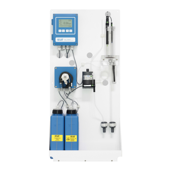
AMI Codes-II Product Description 2.2. Instrument Overview Panel Flow regulating valve Transmitter Sample inlet Peristaltic pump Inlet filter Reagent Oxycon on-line DPD Photometer Reagent Oxycon on-line Buffer Air bubble detector pH sensor Constant head drain Temperature sensor Photometer drain Constant head... -
Page 18: Installation
AMI Codes-II Installation Installation 3.1. Installation Check List Check Instrument’s specification must conform to the National Electrical Code, all state and local codes, and all plant codes and standards for electrical equipment. On site require- 100–240 VAC ( 10%), 50/60 Hz ( 5%) or 24 VDC (±10%), ments isolated power outlet with ground connection and 30 VA. -
Page 19: Mounting Of Instrument Panel
AMI Codes-II Installation Process Make 3 manual measurements. Use a high quality photometer, calibration e.g. Chematest from Swan. Calculate average value and compare this value to the value indicated by the AMI. If necessary, correct the value. The zero point is done automatically before each mea- surement. -
Page 20: Fep Tube At Sample Outlet
AMI Codes-II Installation 3.3.2 FEP Tube at Sample Outlet WARNING Risk of water pollution The drain of the photometer outlet contains DPD. At no means recirculate it into the water system. Tube from photometer Drain Photometer Tube from constant head... -
Page 21: Installation Of Flow Cell
Installation of Flow Cell CAUTION Fragile Part Handle the constant head tube with care. To avoid damage during the transport, the constant head tube [C] of the AMI Codes-II is not installed. Constant head cover Overflow tube Constant head tube Gasket... -
Page 22: Install The Option Ph
3.5. Install the Option pH 3.5.1 pH as Option ex works If the pH option was ordered with the AMI Codes-II, the pH sensor cable as well as the temperature sensor are already connected to the AMI transmitter. Connector cap... -
Page 23: Ph Option As Retrofit Kit
AMI Codes-II Installation 3.5.2 pH Option as Retrofit Kit 2 Clamps with screws Front end PCB pH sensor Temperature sensor Sensor cable Short overflow tube A-96.250.571 / 050517... - Page 24 AMI Codes-II Installation WARNING Risk of electrical shock. Do not perform any work on electrical components if the trans- mitter is switched on. Failure to follow safety instructions could result in serious injury or death. Always turn off AC power before manipulating electric parts.
- Page 25 AMI Codes-II Installation Temperature sensor plug pH sensor plug Front end PCB A B C 7 Open the cover of the AMI transmitter housing. 8 Install the front end PCB. 9 Feed the cable of the pH sensor through one of the cable glands (see Cable thicknesses, p.
-
Page 26: Electrical Connections
AMI Codes-II Installation 3.6. Electrical Connections WARNING Risk of electrical shock. Do not perform any work on electrical components if the trans- mitter is switched on. Failure to follow safety instructions could result in serious injury or death. Always turn off AC power before manipulating electric parts. - Page 27 AMI Codes-II Installation WARNING External Voltage. External supplied devices connected to relay 1 or 2 or to the alarm relay can cause electrical shocks Make sure that the devices connected to the following con- tacts are disconnected from the power before resuming in- stallation.
-
Page 28: Connection Diagram
AMI Codes-II Installation 3.6.1 Connection Diagram CAUTION Use only the terminals shown in this diagram, and only for the mentioned purpose. Use of any other terminals will cause short circuits with possible corresponding consequences to material and personnel. A-96.250.571 / 050517... -
Page 29: Power Supply
Mains cable to comply with standards IEC 60227 or IEC 60245; flammable rating FV1 Mains equipped with an external switch or circuit-breaker – near the instrument – easily accessible to the operator – marked as interrupter for AMI Codes-II A-96.250.571 / 050517... -
Page 30: Input
AMI Codes-II Installation 3.7. Input NOTICE: Use only potential-free (dry) contacts. The total resistance (sum of cable resistance and resistance of the relay contact) must be less than 50 Ω. Terminals 30 and 31 If the signal output is set to hold, the measurement is interrupted if input is active. -
Page 31: Relay 1 And 2
AMI Codes-II Installation 3.8.2 Relay 1 and 2 NOTICE: Max. load 1 A/250 VAC Relay 1 and 2 can be configured as normally open or as normally closed. Standard for both relays is normally open. To configure a Relay as normally closed, set the jumper in the upper position. - Page 32 AMI Codes-II Installation CAUTION Risk of damage of the relays in the AMI Transmitter due to heavy inductive load. Heavy inductive or directly controlled loads (solenoid valves, dosing pumps) may destroy the relay contacts. To switch inductive loads > 0.1 A use an AMI relay box avail- able as an option or suitable external power relays.
-
Page 33: Signal Outputs
AMI Codes-II Installation 3.9. Signal Outputs 3.9.1 Signal Output 1 and 2 (current outputs) NOTICE: Max. burden 510 If signals are sent to two different receivers, use signal isolator (loop isolator). Signal output 1: Terminals 14 (+) and 13 (-) -
Page 34: Signal Output 3
AMI Codes-II Installation 3.10.1 Signal Output 3 Terminals 38 (+) and 37 (-). Requires the additional board for the third signal output 0/4–20 mA. The third signal output can be operated as a current source or as a current sink (switchable via switch [A]). For detailed information see the corresponding installation instruction. -
Page 35: Hart Interface
AMI Codes-II Installation 3.10.3 HART Interface Terminals 38 (+) and 37 (-). The HART interface PCB allows for communication via the HART protocol. For detailed information, consult the HART manual. HART Interface PCB 3.10.4 USB Interface The USB Interface is used to store Logger data and for Firmware upload. -
Page 36: Instrument Setup
AMI Codes-II Instrument Setup Instrument Setup After installation according to checklist proceed as following: 4.1. Prepare Reagents 1 Prepare reagents. See Refill or replace Reagents, p. 2 Insert the suction lances into the canisters. 4.2. Peristaltic Pump The instrument is delivered with opened occlusion frames. -
Page 37: Establish Sample Flow
AMI Codes-II Instrument Setup 4.3. Establish Sample Flow WARNING Water pollution The drain of the photometer outlet contains DPD. At no means recirculate it into the water system. Cover Constant head tube Overflow tube Flow cell block Level Flow regulating valve... -
Page 38: Fill Or Flush Reagent System
AMI Codes-II Instrument Setup 4.4. Fill or Flush Reagent System Fill or flush the reagent tubing: upon the initial instrument setup, after refilling the reagent canisters, before a system shut-down to flush the system with deminer- alized water until no more reagent is left in the system. -
Page 39: Calibration
AMI Codes-II Instrument Setup 4.6. Calibration 1 Calibrate pH sensor (if option pH is installed). Standard pH, p. 2 Perform process calibration. Process Calibration of DIS, p. 50 If ordered: The instrument should be operating for 1h before performing a pH calibration. -
Page 40: Operation
AMI Codes-II Operation Operation 5.1. Keys Exit Enter to exit a menu or command (rejecting any changes) to move back to the previous menu level to move DOWN in a menu list and to decrease digits to move UP in a menu list and to increase digits... -
Page 41: Display
AMI Codes-II Operation 5.2. Display 15:20:18 0.15 23 °C 23 B/s normal operation HOLD input closed or cal delay: Instrument on hold (shows status of signal outputs). input closed: control/limit is interrupted (shows status of signal outputs). ERROR Error Fatal Error... -
Page 42: Software Structure
AMI Codes-II Operation 5.3. Software Structure Main Menu Messages Diagnostics Maintenance Operation Installation Menu Messages 1 Messages Reveals pending errors as well as an event history Pending Errors (time and state of events that have occurred at an Message List earlier point of time). -
Page 43: Changing Parameters And Values
AMI Codes-II Operation 5.4. Changing Parameters and values Changing The following example shows how to change the logger interval: parameters 1 Select the parameter you want to Sensors Logger 5.1.2 4.4.1 change. Sensor type FOME Log interval 30 min 2 Press [Enter] Disinf. -
Page 44: Maintenance
AMI Codes-II Maintenance Maintenance 6.1. Maintenance Schedule WARNING Stop operation before maintenance. Stop sample flow. Shut off power of the instrument. Daily (dirty water) Check sample supply for dirt. up to every Clean all filters and strainers, if necessary. -
Page 45: Stop Of Operation For Maintenance
AMI Codes-II Maintenance 6.2. Stop of Operation for Maintenance 1 Put the suction lances into a bucket with clean water. 2 Start <Fill system>. The reagent tubes are flushed with water. 3 Remove the suction lances from the water. -
Page 46: Refill Or Replace Reagents
AMI Codes-II Maintenance 6.3. Refill or replace Reagents The liquid level in canister 2 is monitored. The following messages are displayed: Canister almost Maintenance E065 - Reagents low and the empty remaining reagent volume in % (starting at 17 % = 340 ml). - Page 47 AMI Codes-II Maintenance Oxycon On-line DPD WARNING Severe eye irritation and severe skin irritation. Concentrated Oxycon On-line DPD contains more than 10% mineral acids. Do not swallow. Avoid any contact with eyes and skin. Wear protective goggles, ...
-
Page 48: Reagents For Free Chlorine, Chlorine Dioxide, Bromine And Iodine
AMI Codes-II Maintenance Canister set up Suction lance without level detector (canister 1) Suction lance with level detector (canister 2) Level detector 2 L mark Canister 1: Oxycon on-line DPD Canister 2: Oxycon on-line Buffer Holder OXYCON ON-LINE OXYCON ON-LINE Pufferlösung... - Page 49 AMI Codes-II Maintenance 6 Put the canister [E] into the holder [G]. 7 Remove the screw cover, insert the suction lance [A] and tight- en the screw cover. Prepare 1 Rinse the canister [F] labelled “OXYCON ON LINE Buffer” solu- tion with demineralized water.
-
Page 50: Reagents For Measuring Monochloramine And Ozone
AMI Codes-II Maintenance 6.3.2 Reagents for Measuring Monochloramine and Ozone 2 L of reagents last for 15 days with 2 min. interval: 1 x 50 ml of Oxycon On-line DPD 1 x 240 gr of Oxycon On-line Buffer ... -
Page 51: Verification
AMI Codes-II Maintenance 6.4. Verification The “Verification kit for AMI Photometer” is available as an accessory. An optical window with a precisely deter- mined absorbance value is placed into the light beam of the photometer. The actual measured absorbance will be compared to the reference value labeled on each kit. -
Page 52: Calibration
AMI Codes-II Maintenance 6.5. Calibration Process NOTICE: Perform process calibration for free chlorine / total Calibration of residual chlorine only if: • the sample concentration is close to the desired process value (stable value) • you are sure that the reagents are mixed completely and correctly •... - Page 53 AMI Codes-II Maintenance Process pH Use a Chematest 25 photometer (or equivalent) to determine the sample pH value. NOTICE: Make sure your reference instrument is calibrated correctly! Maintenance Calibration 3.1.2 Calibration Calibration Process DIS. Enter Service Process pH Simulation Standard pH Set Time 01.01.05 16:30:00...
- Page 54 AMI Codes-II Maintenance Standard pH 1 Navigate to menu <Maintenance>/ Maintenance <Calibration>. Calibration Enter 2 Press [Enter]. Simulation Set Time 01.06.04 16:30:00 3 Remove the pH sensor from the Enter Fill System flow cell. Cleaning 4 Follow the instructions on the dis- Calibration play.
-
Page 55: Cleaning The Protective Filter
AMI Codes-II Maintenance 6.6. Cleaning the protective Filter Switch off the instrument according to instructions in Stop of Opera- tion for Maintenance, p. 43 Flow cell block Flow regulating valve Filter shaft Filter Filter vessel Normally the filter in your sample supply line will retain most debris. -
Page 56: Cleaning The Photometer
AMI Codes-II Maintenance 6.7. Cleaning the Photometer Clean the photometer after indication by alarm (E020, FOME dirty). Switch off the instrument according to instructions in Stop of Opera- tion for Maintenance, p. Material Small brush. Procedure Flow regulating valve Photometer cover... -
Page 57: Cleaning The Flow Cell
AMI Codes-II Maintenance 6.8. Cleaning the Flow Cell CAUTION Acrylic glass parts are fragile and scratch-sensitive. Possible damage of acrylic glass parts due to scrubbing materi- als. Never use organic solvents or scrubbing materials to clean acrylic glass parts. - Page 58 AMI Codes-II Maintenance Constant head cover Overflow tube Constant head tube Flow cell block Flow regulating valve Level Cleaning 1 Switch off the instrument according to instructions in Stop of Operation for Maintenance, p. 43 2 If installed remove the pH sensor and the temperature sensor.
-
Page 59: Assemble The Flow Cell
AMI Codes-II Maintenance 6.8.2 Assemble the Flow Cell Constant head cover Overflow tube Constant head tube Gasket Flow cell block Level 1 Replace the gasket [D] before reassembling the flow cell. NOTICE: A film of teflon paste (e.g. Fomblin from Solvay Solexis) on the gaskets improves tightness and life time. -
Page 60: Maintenance Of Ph Sensor
AMI Codes-II Maintenance 6.9. Maintenance of pH sensor Connector pH sensor shaft Flow cell cover Flow cell Clean 1 Remove the pH sensor [B] from the flow cell. pH sensor 2 Unscrew and remove the connector [A] from the pH sensor. -
Page 61: Tube Replacement
AMI Codes-II Maintenance 6.10. Tube Replacement 6.10.1 Replace the Pump Tubes The pump tube [D] of the peristaltic pump is exposed to a minimal wear. It is therefore recommended to exchange the pump tube annually. CAUTION Pollution of reagents possible. - Page 62 AMI Codes-II Maintenance Dismount The pump tube can easily be dismounted and mounted. pump tubes Proceed as follows: Pump housing Occlusion frame open Rotor Pump tube Pump inlet Pump outlet 1 Switch off the instrument according to instructions in Stop of Operation for Maintenance, p.
-
Page 63: Replace The Reagent Tubes
AMI Codes-II Maintenance 6.10.2 Replace the Reagent Tubes Tube numbering Level from Pump outlet: rear frame Flow cell block: connection 1 see Flow cell block side view Q Pump outlet: front frame Flow cell block: connection 2 see Flow cell block side view Q... -
Page 64: Replacing Fuses
AMI Codes-II Maintenance 6.11. Replacing Fuses WARNING External Voltage. External supplied devices connected to relay 1 or 2 or to the alarm relay can cause electrical shocks. Make sure that the devices connected to the following con- tacts are disconnected from the power before resuming in- stallation. -
Page 65: Longer Stop Of Operation
AMI Codes-II Maintenance 6.12. Longer Stop of Operation 1 Put the suction lances into bucket with clean water. 2 Start <Fill system>. The reagent tubes are flushed with water. 3 Remove the suction lance from the water. 4 Start <Fill system> again. -
Page 66: Troubleshooting
AMI Codes-II Troubleshooting Troubleshooting This chapter provides some hints to make trouble shooting easier. For any detailed information how to handle or clean parts please Maintenance, p. 42. For any detailed information how to pro- gram the instrument please see Program List and Explanations, p. -
Page 67: Calibration Errors
AMI Codes-II Troubleshooting 7.2. Calibration Errors 7.2.1 Process calibration DIS Possible error Slope error: message Possible cause Corrective Action Wrong manual measure- Repeat the manual measurement. ment. Use fresh reagents. Wrong reagent mixture Make a correct mixture. Reagents not ... -
Page 68: Error List
AMI Codes-II Troubleshooting 7.3. Error List Error Non-fatal Error. Indicates an alarm if a programmed value is ex- ceeded. Such Errors are marked E0xx (bold and black). Fatal Error (blinking symbol) Control of dosing devices is interrupted. The indicated measured values are possibly incorrect. - Page 69 AMI Codes-II Troubleshooting Error Description Corrective action – check process E001 DIS. Alarm high – check programmed value in menu 5.3.1.1.1, p. 86 – check process E002 DIS. Alarm Low – check programmed value in menu 5.3.1.1.25, p. 86 – check process...
- Page 70 AMI Codes-II Troubleshooting Error Description Corrective action – check wiring of temperature sensor, see E011 Temp. shorted Connection Diagram, p. 26 – check temperature sensor – check wiring of temperature sensor, see E012 Temp. disconnected Connection Diagram, p. 26 – check temperature sensor –...
- Page 71 AMI Codes-II Troubleshooting Error Description Corrective action – call service E030 EEprom Frontend – call service E031 Calibration Recout – call service E032 Wrong Frontend – none, normal status E033 Power-on – none, normal status E034 Power-down – Operating display, upper status line. The...
-
Page 72: Program Overview
AMI Codes-II Program Overview Program Overview For explanations about each parameter of the menus see Program List and Explanations, p. Menu 1 Messages informs about pending errors and mainte- nance tasks and shows the error history. Password protection possible. No settings can be modified. -
Page 73: Maintenance (Main Menu 3)
AMI Codes-II Program Overview Front End Operating Time Years / Days / Hours / Minutes / Seconds 2.1.5.1* 2.1.5* Sensors Photometer Current Value 2.2* 2.2.1* (Raw value) Absorbance Cal. History Number 2.2.1.4.1* 2.2.1.4* Date, Time Slope Ver. History Number 2.2.1.5.1* 2.2.1.5*... -
Page 74: Operation (Main Menu 4)
AMI Codes-II Program Overview 3.1.2* Offset Process Value 3.1.2.4* Standard pH (Progress) 3.1.3.5* 3.1.3* Service Verification (Progress) 3.2.1.1* 3.2* 3.2.1* Fill System (Progress) 3.2.2.5* 3.2.2* Simulation Alarm Relay 3.3.1* 3.3* Relay 1 3.3.2* Relay 2 3.3.3* Signal Output 1 3.3.4* Signal Output 2 3.3.5*... -
Page 75: Installation (Main Menu 5)
AMI Codes-II Program Overview 4.2.1.2* Alarm Low 4.2.1.2.x* Hysteresis 4.2.1.2.x* Delay 4.2.1.2.x* Relay 1& 2 Setpoint 4.2.x.x* 4.2.2* & 4.2.3* Hysteresis 4.2.x.x* Delay 4.2.x.x* Input Active 4.2.4.1* 4.2.4* Signal Outputs 4.2.4.2* Output / Control 4.2.4.3* Fault 4.2.4.4* Delay 4.2.4.5* Logger Log Interval 4.3.1*... - Page 76 AMI Codes-II Program Overview Sample Flow Flow Alarm 5.3.1.3.1* 5.3.1.3* Alarm High 5.3.1.3.x* Alarm Low 5.3.1.3.x* Sample Temp. Alarm High 5.3.1.4.1* 5.3.1.4* Alarm Low 5.3.1.4.x* Case Temp. high 5.3.1.5* Case Temp. low 5.3.1.6* Relay 1&2 Function 5.3.2.1 & 5.3.3.1* 5.3.2* & 5.3.3* Parameter 5.3.2.x &...
-
Page 77: Program List And Explanations
AMI Codes-II Program List and Explanations Program List and Explanations 1 Messages 1.1 Pending Errors 1.1.5 Provides the list of active errors with their status (active, acknowledged). If an active error is acknowledged, the alarm relay is active again. Cleared errors are moved to the Message list. - Page 78 AMI Codes-II Program List and Explanations 2.2.1.5 Ver. History: Shows the verification values of the last verifications: Number: Verification counter. Date, Time: Date and time of the verification. Absorbance: Measured absorbance of the reference kit. Reference value: True value of the reference kit according to label.
- Page 79 AMI Codes-II Program List and Explanations 2.3 Sample 2.3.1 Sample ID: Shows the identification assigned to a sample. This identification is defined by the user to identify the location of the sample. Sample Flow: Shows the actual sample flow in B/s (bubbles per second)].
-
Page 80: Maintenance
AMI Codes-II Program List and Explanations 3 Maintenance 3.1 Calibration In this menu, you can correct measuring values (all disinfectants and pH) or calibrate offset and slope of pH electrode. 3.1.1 Process DIS: Possibility to correct the disinfectant value. See Process Calibration of DIS, p. - Page 81 3.4 Set Time Adjust date and time. 3.5 Cleaning Automatic cleaning process using the Cleaning module-II controlled by transmitter of AMI Codes-II. Measurement is interrupted. Flow error interrupts cleaning. Cleaning does not start: E022 Reagent empty, E023 Cleaning solution, no flow.
-
Page 82: Operation
AMI Codes-II Program List and Explanations 4 Operation 4.1 Sensors 4.1.1 Filter Time Constant: Used to damp noisy signals. The higher the filter time constant, the slower the system reacts to changes of the measured value. Range: 5–300 sec 4.1.2 Hold after Cal: Delay permitting the instrument to stabilize again after calibration. -
Page 83: Installation
AMI Codes-II Program List and Explanations 5 Installation 5.1 Sensors 5.1.1 Disinf: Select the disinfectant in use. Available disinfectants are: Free chlorine Hypochl. acid Ozone Chlorine dioxide Bromine Iodine Monochloramine 5.1.2 Dimension: The measuring value can be displayed as ppm or mg/l 5.1.3... - Page 84 AMI Codes-II Program List and Explanations 5.2 Signal Outputs 5.2.1 and 5.2.2 Signal Output 1 and 2: Assign process value, the current loop range and a function to each signal output. NOTICE: The navigation in the menu <Signal Output 1> and <Signal Output 2>...
- Page 85 AMI Codes-II Program List and Explanations [mA] 0 / 4 1’000 10’000 X Measured value (logarithmic) 5.2.1.40 Scaling: Enter beginning and end point (Range low & high) of the linear or logarithmic scale. In addition, the midpoint for the bilinear scale.
- Page 86 AMI Codes-II Program List and Explanations As control Signal outputs can be used for driving control units. We distinguish different kinds of controls: output P-controller: The controller action is proportional to the devia- tion from the setpoint. The controller is characterized by the P-Band.
- Page 87 AMI Codes-II Program List and Explanations Control upwards/downwards Setpoint: User-defined process value (Measured value or flow) P-Band: Range below (upwards control) or above (downwards control) the set-point, within the dosing intensity is reduced from 100% to 0% to reach the set-point without overshooting.
- Page 88 AMI Codes-II Program List and Explanations 5.3 Relay Contacts 5.3.1 Alarm Relay: The alarm relay is used as cumulative error indicator. Under normal operating conditions the contact is active. The contact is inactive at: Power loss Detection of system faults like defective sensors or electronic parts ...
- Page 89 AMI Codes-II Program List and Explanations 5.3.1.2.1 Alarm High: If the measured value rises above the alarm high value, the alarm relay is activated and E003 is displayed in the message list. Range: 0–14.00 pH 5.3.1.2.21 Alarm Low: If the measured value falls below the alarm low value,...
- Page 90 AMI Codes-II Program List and Explanations 5.3.1.4 Sample Temperature: Only available if pH option is installed. Define the measuring value, which should issue an alarm high respectively low. 5.3.1.4.1 Alarm High: If the sample temperature rises above the programmed value E007 is issued.
- Page 91 AMI Codes-II Program List and Explanations 5.3.2.1 Function = Limit upper/lower: When the relays are used as upper or lower limit switches, program the following: 5.3.2.20 Parameter: select a process value 5.3.2.300 Setpoint: If the measured value rises above respectively falls below the set-point, the relay is activated.
- Page 92 AMI Codes-II Program List and Explanations 5.3.2.1 Function = Control upwards/downwards: The relays may be used to drive control units such as solenoid valves, membrane dosing pumps or motor valves. When driving a motor valve both relays are needed, relay 1 to open and relay 2 to close the valve.
- Page 93 AMI Codes-II Program List and Explanations 5.3.2.32.31 Control Parameters Range for each Parameter same as 5.2.1.43, p. 85 5.3.2.32.1 Actuator = Motor valve Dosing is controlled by the position of a motor driven mixing valve. 5.3.2.32.22 Run time: Time needed to open a completely closed valve Range: 5–300 sec.
- Page 94 AMI Codes-II Program List and Explanations 5.3.2.7 Output/Control: Select operating mode of the controller output: Cont.: Controller continues normally. Hold: Controller continues based on the last valid value. Off: Controller is switched off. 5.3.2.24 daily The relay contact can be activated daily, at any time of a day.
- Page 95 AMI Codes-II Program List and Explanations 5.3.2.1 Function = Fieldbus: The relay will be switched via the Profibus input. No further param- eters are needed. 5.3.3.1 Function = End of Batch This function is only available on relay 2. It is used to communicate with canal switching instruments from third-party suppliers.
- Page 96 AMI Codes-II Program List and Explanations 5.3.4.4 Fault: No message is issued in pending error list and the alarm relay does not close when input is active. Message E024 is stored in the message list. Yes: Message E024 is issued and stored in the message list.
- Page 97 AMI Codes-II Program List and Explanations 5.5 Interface Select one of the following communication protocols. Depending on your selection, different parameters must be defined. 5.5.1 Protocol: Profibus 5.5.20 Device address: Range: 0–126 5.5.30 ID-Nr.: Range: Analyzer; Manufacturer; Multivariable 5.5.40 Local operation: Range: Enabled, Disabled 5.5.1...
-
Page 98: Material Safety Data Sheets
AMI Codes-II Material Safety Data sheets Material Safety Data sheets 10.1. Reagents Catalogue No.: A-85.410.120 Product name: OXYCON ON-LINE DPD Catalogue No.: A-85.410.120 Product name: OXYCON ON-LINE Buffer Catalogue No: A-85.419.200 Product name: OXYCON ON-LINE KI Catalogue No.: A-85.112.300 Product name: Calibration Solution pH 4 Catalogue No.:... -
Page 99: Default Values
AMI Codes-II Default Values Default Values NOTICE: The parameter Cleaning is only visible if an optional Cleaning Module is connected to the AMI Codes II. The parameters pH and Temperature are only visible if the option pH is installed. Operation: Sensors: Filter Time Const.: .............. - Page 100 AMI Codes-II Default Values pH: Alarm high: ..............14.00 pH pH: Alarm low:..............0.00 pH pH: Hysteresis: ..............0.10 pH pH: Delay: ................5 Sec Sample Flow: Flow Alarm: ............yes Sample Flow: Alarm High: ............500 B/s Sample Flow: Alarm Low: ............5 B/s Sample Temp.: Alarm High: .............55 °C...
- Page 101 AMI Codes-II Default Values Settings: Actuator: ..........Time proportional Cycle time: ................60 s Response time: ..............10 s Settings: Actuator ............Motor valve Run time: ................60 s Neutral zone: ................5% If Function = Timer: Mode:..................Interval Interval: ................1 min Mode: ..................daily...
-
Page 102: Index
AMI Codes-II Index Index ..... . . Accuracy Input ..Alarm Instrument Setup ... . - Page 103 AMI Codes-II Index ... . Profibus ..– Terminals ..Tube numbering ..Reagent consumption ..
-
Page 104: Notes
AMI Codes-II Notes Notes A-96.250.571 / 050517... - Page 105 AMI Codes-II Notes A-96.250.571 / 050517...
- Page 106 AMI Codes-II SWAN is represented worldwide by subsidiary companies and distributors. cooperates with independent representatives all over the world. SWAN Products Analytical Instruments for: High Purity Water Feedwater, Steam and Condensate Potable Water Pool and Sanitary Water Cooling Water Waste Water and Effluents Made in Switzerland A-96.250.571 / 050517...
Need help?
Do you have a question about the AMI Codes-II and is the answer not in the manual?
Questions and answers
Using the AMI Codes-II, there is Chlorine in the system, yet the system reads 0.00. Reseted, still no feedback. what could be the problem.
If the Swann AMI Codes-II system reads 0.00 for chlorine despite chlorine being present, possible issues could include:
1. Reagent Issues – The required reagents (OXYCON ON-LINE DPD, buffer solutions, etc.) might be depleted, expired, or improperly mixed.
2. Clogged or Dirty Components – The sample inlet, inlet filter, or flow regulating valve might be clogged, preventing proper water flow.
3. Calibration or Sensor Issues – The system may need recalibration, or the sensor might be faulty or improperly installed.
4. Power or Electrical Issues – The instrument may not be receiving proper power, or there could be an electrical fault affecting measurement.
5. Interference from Additives – Certain water additives like corrosion inhibitors or cyanuric acid might interfere with chlorine detection.
Checking reagent levels, cleaning components, recalibrating, and verifying power and water flow can help identify and resolve the issue.
This answer is automatically generated
Please share Data Sheet for the Pherispatic Pump