Table of Contents
Advertisement
Quick Links
Advertisement
Table of Contents

Related Manuals for Swann AMI Deltacon DG


Summary of Contents for Swann AMI Deltacon DG
- Page 1 A-96.250.491 / 190121 Operator’s Manual Firmware V6.21 and higher AMI Deltacon DG...
- Page 2 For any technical question, contact your nearest Swan representative, or the manufacturer: Swan Analytische Instrumente AG Studbachstrasse 13 8340 Hinwil Switzerland Document Status AMI Deltacon DG Operator’s Manual Title: A-96.250.491 Revision Issue Sept. 2009 Preliminary Edition Nov. 2009 Update to FW release 4.12...
-
Page 3: Table Of Contents
AMI Deltacon DG Table of Contents Safety Instructions .......... - Page 4 AMI Deltacon DG Maintenance ........... 37 6.1.
-
Page 5: Safety Instructions
AMI Deltacon DG Safety Instructions AMI Deltacon DG–Operator’s Manual This document describes the main steps for instrument setup, opera- tion and maintenance. Safety Instructions General The instructions included in this section explain the potential risks associated with instrument operation and provide important safety practices designed to minimize these risks. -
Page 6: Warning Notices
AMI Deltacon DG Safety Instructions 1.1. Warning Notices The symbols used for safety-related notices have the following meaning: DANGER Your life or physical wellbeing are in serious danger if such warn- ings are ignored. Follow the prevention instructions carefully. - Page 7 AMI Deltacon DG Safety Instructions Warning Signs The warning signs in this manual have the following meaning: Electrical shock hazard Corrosive Harmful to health Flammable Warning general Attention general A-96.250.491 / 190121...
-
Page 8: General Safety Regulations
AMI Deltacon DG Safety Instructions 1.2. General Safety Regulations Legal The user is responsible for proper system operation. All precautions must be followed to ensure safe operation of the instrument. Requirements Spare Parts Use only official SWAN spare parts and disposables. If other parts are used during the normal warranty period, the manufacturer’s war-... -
Page 9: Restriction For Use
AMI Deltacon DG Safety Instructions 1.3. Restriction for use The AMI Deltacon DG is designed for determination of: specific (total) conductivity cation (acid) conductivity after the cation exchanger degassed conductivity after a sample reboiler in water-steam- cycles only. -
Page 10: Product Description
Product Description 2.1. Description of the System Application The AMI Deltacon DG is a complete monitoring system for the auto- matic, continuous measurement of the conductivity before (specific Range conductivity) and after a cation exchanger (cationic or acid conduc- tivity) and the conductivity of the re-boiled sample (degassed con- ductivity). - Page 11 AMI Deltacon DG Product Description Relays Two potential-free contacts programmable as limit switches for mea- suring values, controllers or timer for system cleaning with automatic hold function. Both contacts can be set as normally open or normally closed with a jumper.
- Page 12 AMI Deltacon DG Product Description Cation Con- The alkalization agent is removed in the cation column. All cationic ions are exchanged with H+, all anionic impurities (ions with negative ductivity (Acid charge) pass through the column unchanged. Conductivity) Degassed After the heat exchanger the sample is heated up to 0.5 °C below the boiling point.
- Page 13 AMI Deltacon DG Product Description Fluidics overview Conductivity sensor (sc) Deaeration tube cation exchanger bottle Conductivity sensor (cc) Conductivity sensor (dc) Heat exchanger Heat exchanger pressure Connection tube relief tube Heater Heater pressure relief tube Sample inlet Cation exchanger bottle...
-
Page 14: Instrument Specification
AMI Deltacon DG Product Description 2.2. Instrument Specification Power Supply Voltage: 100–127 VAC and 200–240 VAC (±10%) 50/60 Hz (±5%) Max. current: Voltage at 90 VAC: 12 A Voltage at 140 VAC: 19 A Voltage higher than 180 VAC: 9.5 A Max. - Page 15 AMI Deltacon DG Product Description Dimensions Stainless steel Panel: 570 x 850 x200 mm Dimensions: 8 mm Screws: 26 kg Weight: 570 mm / 22.44" 254 mm / 10.00" 290 mm / 11.42" Exit Enter AMI Deltacon ! WARNING !
-
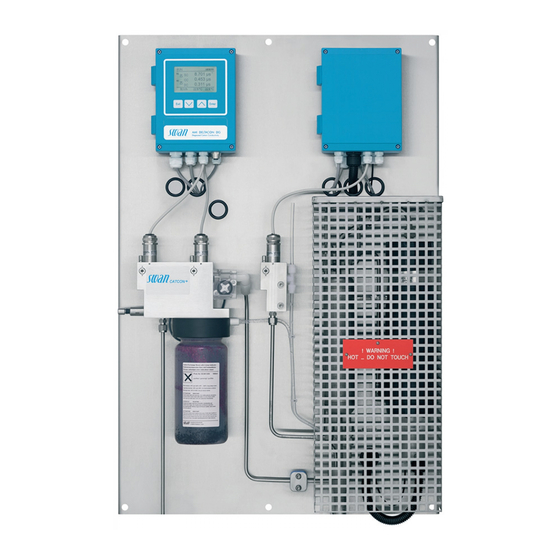
Page 16: Instrument Overview
AMI Deltacon DG Product Description 2.3. Instrument Overview Panel Cation exchanger Transmitter Sample inlet Specific conductivity sensor Degasser controller Cation conductivity sensor Degassed conductivity sensor Flow cell 1, sc, cc Flow cell 2, dc Heater Flow meter Flow regulating valve... -
Page 17: Installation
AMI Deltacon DG Installation Installation 3.1. Installation Checklist Monitors On-site require- 100–127 VAC, 200–240 VAC (±10%), 50/60 Hz (±5 %) ments power outlet with ground connection and 2.6 kW Sample line with sufficient sample flow and pressure (see Instru- ment Specification, p. -
Page 18: Mounting Of Instrument Panel
AMI Deltacon DG Installation 3.2. Mounting of Instrument Panel The first part of this chapter describes the preparing and placing of the system for use. The instrument must only be installed by trained personnel. Mount the instrument in vertical position. - Page 19 AMI Deltacon DG Installation Stainless steel tube Compression cone Union nut Body Compression ferrule Tightened connection Waste Connect the waste tube to the waste funnel. CAUTION Hot water and steam Hot water and steam leaves the sample outlet, PVC tubes can be damaged.
-
Page 20: Installation Of Cation Exchanger
AMI Deltacon DG Installation 3.4. Installation of Cation Exchanger Cation ex- The bottle containing the cation exchanger is delivered separately. For transport, an empty bottle is installed into the bottle holder. changer bottle Flow cell Bottle holder Manual deaeration valve... -
Page 21: Electrical Connections
AMI Deltacon DG Installation 3.5. Electrical Connections WARNING Electrical hazard. Always turn off power before manipulating electric parts. Grounding requirements: Only operate the instrument from a power outlet which has a ground connection. Make sure the power specification of the instrument corre- sponds to the power on site. - Page 22 AMI Deltacon DG Installation WARNING External Voltage. External supplied devices connected to relay 1 or 2 or to the alarm relay can cause electrical shocks Make sure that the devices connected to the following contacts are disconnected from the power before resuming installation.
-
Page 23: Connection Diagram
AMI Deltacon DG Installation 3.5.1 Connection Diagram CAUTION Use only the terminals shown in this diagram, and only for the mentioned purpose. Use of any other terminals will cause short circuits with possible corresponding consequences to material and personnel. A-96.250.491 / 190121... -
Page 24: Power Supply
Mains cable complies with standards IEC 60227 or IEC 60245; flammable rating FV1 Mains equipped with an external switch or circuit-breaker – near the instrument – easily accessible to the operator – marked as interrupter for AMI Deltacon DG A-96.250.491 / 190121... -
Page 25: Input
AMI Deltacon DG Installation 3.6. Input Note: Use only potential-free (dry) contacts. The total resistance (sum of cable resistance and resistance of the relay contact) must be less than 50 Ω. Terminals 16/42 For programming see Program List and Explanations, p. -
Page 26: Relay 1 And 2
AMI Deltacon DG Installation 3.7.2 Relay 1 and 2 Note: Max. load 1 A / 250 VAC Relay 1 and 2 can be configured as normally open or as normally closed. Standard for both relays is normally open. To configure a Re- lay as normally closed, set the jumper in the upper position. - Page 27 AMI Deltacon DG Installation CAUTION Risk of damage of the relays in the AMI Transmitter due to heavy inductive load. Heavy inductive or directly controlled loads (solenoid valves, dos- ing pumps) may destroy the relay contacts. To switch inductive loads > 0.1 A use an AMI relay box avail- able as an option or suitable external power relays.
-
Page 28: Signal Outputs
AMI Deltacon DG Installation 3.8. Signal Outputs 3.8.1 Signal Output 1 and 2 (current outputs) Note: Max. burden 510 Ω. If signals are sent to two different receivers, use signal isolator (loop isolator). Signal output 1: Terminals 14 (+) and 13 (-) -
Page 29: Signal Output 3
AMI Deltacon DG Installation 3.9.1 Signal Output 3 Terminals 38 (+) and 37 (-). Requires the additional board for the third signal output 0/4–20 mA. The third signal output can be operated as a current source or as a current sink (switchable via switch [A]). For detailed information see the corresponding installation instruction. -
Page 30: Hart Interface
AMI Deltacon DG Installation 3.9.3 HART Interface Terminals 38 (+) and 37 (-). The HART interface PCB allows for communication via the HART protocol. For detailed information, consult the HART manual. HART Interface PCB 3.9.4 USB Interface The USB Interface is used to store Logger data and for Firmware upload. -
Page 31: Instrument Setup
AMI Deltacon DG Instrument Setup Instrument Setup After the analyzer is installed according to the previous instructions, connect the power cord. Do not switch on power, yet! 4.1. Establish sample flow 1 Open flow regulating valve, see Fluidics overview, p. - Page 32 AMI Deltacon DG Instrument Setup Calculations Menu 5.1.1.1 Set <Calculations> to “Yes” if you want to have pH and alkalization agent calculated and displayed. Measuring unit Menu 5.1.1.2 Set the <Measuring unit> according to your requirements: S/cm S/m Monitoring of Menu 5.1.1.3...
-
Page 33: Operation
AMI Deltacon DG Operation Operation 5.1. Keys Exit Enter to exit a menu or command (rejecting any changes) to move back to the previous menu level to move DOWN in a menu list and to decrease digits to move UP in a menu list and to increase digits... - Page 34 AMI Deltacon DG Operation Example of Display 2 15:20:18 8.455 µS 0.178 µS 9.5 l/h 22.1°C 35.8°C normal operation HOLD input closed or cal delay: Instrument on hold (shows status of signal outputs). input closed: control/limit is interrupted (shows status of signal outputs).
-
Page 35: Software Structure
AMI Deltacon DG Operation 5.3. Software Structure Main Menu Messages Diagnostics Maintenance Operation Installation Menu Messages 1 Messages Reveals pending errors as well as an event history Pending Errors (time and state of events that have occurred at an Maintenance List earlier point of time). -
Page 36: Changing Parameters And Values
AMI Deltacon DG Operation 5.4. Changing Parameters and values Changing The following example shows how to change the logger interval: parameters 1 Select the parameter you want to Sensors Logger 5.1.2 4.4.1 change. Sensor type FOME Log interval 30 min 2 Press [Enter] Disinf. -
Page 37: Maintenance
AMI Deltacon DG Maintenance Maintenance 6.1. Maintenance Schedule Check sample flow. Monthly If monitoring of resin has been switched off: Check cation exchanger resin. The resin color changes to red/orange if exhausted. Clean conductivity sensors If required ... -
Page 38: Maintenance Of The Sensor
AMI Deltacon DG Maintenance 6.3. Maintenance of the Sensor Conductivity sensor Security pin unlocked Locking screw open Security pin locked Alignment marks Locking screw closed 6.3.1 Remove the Sensor from the Flow Cell To remove the sensor form the flow cell proceed as follows: 1 Press the security pin [B] down. -
Page 39: Replace The Ion Exchanger
AMI Deltacon DG Maintenance 6.4. Replace the Ion Exchanger The resin of the ion exchanger changes its color from dark violet to brown if the capacity is exhausted. The resin should be changed be- fore no violet resin is left or the cation conductivity rises above the normal value. - Page 40 AMI Deltacon DG Maintenance 9 Open the flow regulating valve and adjust the sample flow. 10 After a few minutes close the manual deaeration valve. 11 Pre-rinse the new cation exchanger resin until the display shows stable measuring values. Operation time 1 liter Swan resin This graphic shows the average exhaust time (flow 6 l/h) and must be verified by the user.
-
Page 41: Changing The Inlet Filter
AMI Deltacon DG Maintenance 6.5. Changing the inlet filter The inlet filter of the cation exchanger prevents the resin from enter- ing the flow cell. It is located in the inlet filter holder [B]. Bottle holder Inlet filter holder Allen screws Inlet filter 1 Stop sample flow. -
Page 42: Longer Stop Of Operation
AMI Deltacon DG Maintenance 6.6. Longer Stop of Operation 1 Stop sample flow. 2 Slightly squeeze the ion exchanger bottle. Thus no water will spill out of the flow cell when loosening the bottle. 3 Unscrew and carefully remove the ion exchanger bottle with the exhausted resin. -
Page 43: Troubleshooting
AMI Deltacon DG Troubleshooting Troubleshooting This chapter provides some hints to make troubleshooting easier. For any detailed information how to replace or clean parts please see chapter Maintenance, p. For any detailed information how to program the instrument please see chapter Program List and Explanations, p. -
Page 44: Error List
AMI Deltacon DG Troubleshooting 7.1. Error List Error Non-fatal Error. Indicates an alarm if a programmed value is exceed- Such Errors are marked E0xx (bold and black). Fatal Error (blinking symbol) Control of dosing devices is interrupted. The indicated measured values are possibly incorrect. - Page 45 AMI Deltacon DG Troubleshooting Error Description Corrective action – check process E001 Cond. 1 Alarm high – check programmed value, see 5.3.1.1, p. 68 – check process E002 Cond. 1 Alarm low – check programmed value, see 5.3.1.1, p. 68 –...
- Page 46 AMI Deltacon DG Troubleshooting Error Description Corrective action – Check wiring of temperature sensor E012 Temp. 1 disconnected – Check temperature sensor – check case/environment temperature E013 Case Temp. high – check programmed value, see 5.3.1.4.1, p. 71 – check case/environment temperature E014 Case Temp.
- Page 47 AMI Deltacon DG Troubleshooting Error Description Corrective action – check process E033 pH Alarm high – check programmed value, see 5.3.1.1.4.1, p. 69 – check process E034 pH Alarm low – check programmed value, see 5.3.1.1.4.25, p. 70 – check process...
-
Page 48: Replacing Fuses
AMI Deltacon DG Troubleshooting 7.2. Replacing Fuses 7.2.1 Fuses in the AMI Transmitter WARNING External Voltage. External supplied devices connected to relay 1 or 2 or to the alarm relay can cause electrical shocks Make sure that the devices connected to the following contacts are disconnected from the power before resuming installation. -
Page 49: Fuses In The Degasser Control Unit
AMI Deltacon DG Troubleshooting 7.2.2 Fuses in the Degasser Control Unit WARNING Electrical hazard. Always turn off power before manipulating electric parts. 12.5 AT/250V Heater 12.5 AT/250V Heater A-96.250.491 / 190121... -
Page 50: Program Overview
AMI Deltacon DG Program Overview Program Overview For explanations about each parameter of the menus see Program List and Explanations, p. 56 Menu 1 Messages informs about pending errors and mainte- nance tasks and shows the error history. Password protection possible. -
Page 51: Diagnostics (Main Menu 2)
AMI Deltacon DG Program Overview 8.2. Diagnostics (Main Menu 2) Identification * Menu numbers Designation AMI Deltacon 2.1* Version V6.21-04/17 Degasser Factory Test 2.1.4.1* Instrument 2.1.4* Motherboard Front End Degasser 1 Degasser 2 Operating Time 2.1.5.1* Years / Days / Hours / Minutes / Seconds 2.1.5*... -
Page 52: Maintenance (Main Menu 3)
AMI Deltacon DG Program Overview Sample 2.3.1* * Menu numbers Sample ID 2.3* Sample Flow 2.3.2.1* Sample Flow 2.3.2* Raw value Sample Temp. Temp.1 2.3.3.1* 2.3.3* (Pt1000) Temp.2 (Pt1000) Temp.3 (Pt1000) Resin capacity (%) Change of resin (date) I/O State 2.4.1*... -
Page 53: Operation (Main Menu 4)
AMI Deltacon DG Program Overview 8.4. Operation (Main Menu 4) Sensors Filter Time Const. 4.1.1* * Menu numbers 4.10* 4.1.2* Hold after Cal Relay Contacts Alarm Relay Cond. 1 (sc) 4.2.1.1.1* Alarm High 4.2* 4.2.1* 4.2.1.1* 4.2.1.1.25* Alarm Low 4.2.1.1.35*... -
Page 54: Installation (Main Menu 5)
AMI Deltacon DG Program Overview 8.5. Installation (Main Menu 5) Sensors Miscellaneous 5.1.1.1* * Menu numbers Calculations 5.1* 5.1.1* Maes. unit 5.1.1.2* 5.1.1.3* Monitoring of resin 5.1.1.4* Resin Capacity 5.1.1.5* Volume of resin Sensor parameters Sensor 1 5.1.2.1.1* Cell Constant 5.1.2*... - Page 55 AMI Deltacon DG Program Overview Cond. 3 (cc) Alarm High 5.3.1.1.2* Alarm Low Hysteresis * Delay Sample Temp. Temp. 1 Alarm High 5.3.1.2* 5.3.1.2.1* Alarm Low Temp. 2 Alarm High 5.3.1.2.2* Alarm Low Temp. 3 Alarm High 5.3.1.2.3* Alarm Low...
-
Page 56: Program List And Explanations
AMI Deltacon DG Program List and Explanations Program List and Explanations 1 Messages 1.1 Pending Errors 1.1.5 Provides the list of active errors with their status (active, acknowl- edged). If an active error is acknowledged, the alarm relay is active again. - Page 57 AMI Deltacon DG Program List and Explanations 2.2.1.3 Sensor 3: Shows the Current value in µS Raw value in µS Cell Constant 2.2.2 Miscellaneous: 2.2.2.1 Case Temp: Shows the current temperature in [°C] inside the trans- mitter. 2.2.4 Degasser 2.2.4.1 Heater: Current sample temperature in °C.
-
Page 58: Maintenance
AMI Deltacon DG Program List and Explanations 2.4 I/O State Shows current status of all in- and outputs. 2.4.1 Active or inactive Alarm Relay: Active or inactive Relay 1/2: Open or closed Input: Actual current in mA Signal Output 1/2:... -
Page 59: Operation
AMI Deltacon DG Program List and Explanations 3.3 Change of Resin Yes or No: After exchanging the resin bottle navigate to this menu, press [Enter], select <Yes>, press [Exit] and confirm with <Yes>. With this action the resin capacity is set to 100% and the current date is saved. -
Page 60: Installation
AMI Deltacon DG Program List and Explanations Interval 1 min 5 min 10 min 30 min Time 25 min 25 h 10 d 31 d 62 d 4.3.2 Clear Logger: If confirmed with <yes>, the complete logger data is deleted. A new data series is started. - Page 61 AMI Deltacon DG Program List and Explanations 5.1.1.3 Monitoring of resin: Select “yes” if consumption of cation resin should be calculated and displayed. Replacement of exhausted resin must now be confirmed in menu <Maintenance>. 5.1.1.4 Resin Capacity: Enter the resin capacity.
- Page 62 AMI Deltacon DG Program List and Explanations 5.1.2.3.5 Temp. comp: 5.1.2.2.3.1 Comp.: Available compensation models: Strong acids 5.1.2.4 Degasser 5.1.2.4.1 Mode: on, off, input On: The degasser is switched on. Off: The degasser is switched off. Input: The degasser can be switched on or off via signal input.
- Page 63 AMI Deltacon DG Program List and Explanations 5.2.1.2 Current Loop: Select the current range of the signal output. Make sure the connected device works with the same current range. Available ranges: 0–20 mA or 4–20 mA 5.2.1.3 Function: Define if the signal output is used to transmit a process val- ue or to drive a control unit.
- Page 64 AMI Deltacon DG Program List and Explanations 5.2.1.40 Scaling: Enter beginning and end point (Range low & high) of the linear or logarithmic scale. In addition, the midpoint for the bilinear scale. Parameter Cond. 1 (sc): 5.2.1.40.10 Range low: 0 –3000 S 5.2.1.40.20...
- Page 65 AMI Deltacon DG Program List and Explanations As control Signal outputs can be used for driving control units. We distinguish different kinds of controls: output P-controller: The controller action is proportional to the devia- tion from the setpoint. The controller is characterized by the P- Band.
- Page 66 AMI Deltacon DG Program List and Explanations Control upwards or downwards Setpoint: User-defined process value for the selected parameter. P-Band: Range below (upwards control) or above (downwards con- trol) the set-point, within the dosing intensity is reduced from 100% to 0% to reach the setpoint without overshooting.
- Page 67 AMI Deltacon DG Program List and Explanations 5.2.1.43 Control Parameters: if Parameters = Difference 5.2.1.43.16 Setpoint Range: 0 –3000 S 5.2.1.43.26 P-Band: Range: 0 –3000 S 5.2.1.43 Control Parameters: if Parameters = Sample flow 5.2.1.43.17 Setpoint Range: 0 –20 l/h 5.2.1.43.27...
- Page 68 AMI Deltacon DG Program List and Explanations 5.3 Relay Contacts 5.3.1 Alarm Relay: The alarm relay is used as cumulative error indicator. Under normal operating conditions the contact is active. The contact is inactive at: Power loss Detection of system faults like defective sensors or electronic parts ...
- Page 69 AMI Deltacon DG Program List and Explanations 5.3.1.1.2 Cond. 2 (cc) 5.3.1.1.2.1 Alarm High: If the measured value rises above the alarm high value, the alarm relay is activated and E003, is displayed in the message list. Range: 0–3000 S 5.3.1.1.2.25...
- Page 70 AMI Deltacon DG Program List and Explanations 5.3.1.1.4.25 Alarm Low: If the measured value falls below the alarm low value, the alarm relay is activated and E034 is displayed in the message list. Range: 0–14 pH 5.3.1.1.4.35 Hysteresis: Within the hyst. range, the relay does not switch. This prevents damage of relays contacts when the measured value fluctu- ates around the alarm value.
- Page 71 AMI Deltacon DG Program List and Explanations 5.3.1.2.2 Temp. 2 5.3.1.2.2.1 Alarm High: If the measured value rises above the alarm high value, the alarm relay is activated and E037, is displayed in the message list. Range: 30–200 °C 5.3.1.2.2.25...
- Page 72 AMI Deltacon DG Program List and Explanations 5.3.1.4.2 Alarm low: Set the alarm low value for temperature of electronics housing. If the value falls below the programmed value E014 is is- sued. Range: -10 to +20 °C 5.3.2 & 3 Relay 1 and 2: The contacts can be set as normally open or normal- ly closed with a jumper.
- Page 73 AMI Deltacon DG Program List and Explanations 5.3.2.400 Hysteresis: within the hysteresis range, the relay does not switch. This prevents damage of relay contacts when the measured value fluctuates around the alarm value. Parameter Range Cond. 1 (sc) 0.000 –3000 S Cond.
- Page 74 AMI Deltacon DG Program List and Explanations 5.3.2.32 Settings: Choose the respective actuator: Time proportional Frequency Motor valve 5.3.2.32.1 Actuator = Time proportional Examples of metering devices that are driven time proportional are solenoid valves, peristaltic pumps.
- Page 75 AMI Deltacon DG Program List and Explanations 5.3.2.24 Mode: Operating mode (interval, daily, weekly) 5.3.2.24 Interval 5.3.2.340 Interval: The interval can be programmed within a range of 1–1’440 min. 5.3.2.44 Run Time: Enter the time the relay stays active. Range: 5–32’400 sec.
- Page 76 AMI Deltacon DG Program List and Explanations 5.3.2.6 Signal Outputs: see Interval 5.3.2.7 Output/Control: see Interval 5.3.2.24 weekly The relay contact can be activated at one or several days, of a week. The daily starting time is valid for all days.
- Page 77 AMI Deltacon DG Program List and Explanations 5.3.4.2 Signal Outputs: Select the operation mode of the signal outputs when the relay is active: Signal outputs continue to issue the measured Continuous: value. Signal outputs hold the last valid measured value.
- Page 78 AMI Deltacon DG Program List and Explanations 5.4.4 Password: Select a password different from 0000 to prevent unau- thorized access to the menus “Messages”, “Maintenance”, “Opera- tion” and “Installation”. Each menu may be protected by a different password. If you forgot the passwords, contact the closest SWAN representa- tive.
-
Page 79: Material Safety Data Sheets
AMI Deltacon DG Material Safety Data sheets Material Safety Data sheets 10.1. Swan Cation Exchange Resin Product name: Cation Exchange Resin Catalogue number: A-82.841.030 and A-82.841.031 Download The current Material Safety Data Sheets (MSDS) for the above listed Reagents are available for downloading at www.swan.ch. -
Page 80: Default Values
AMI Deltacon DG Default Values Default Values Operation: Sensors: Filter Time Const.: ................20 s Hold after Cal.:................0 s Relay Contacts Alarm Relay .............same as in Installation Relay 1/2............same as in Installation Input..............same as in Installation Logger: Logger Interval:................ 30 min Clear Logger:.................. - Page 81 AMI Deltacon DG Default Values Alarm Relay: Conductivity; Cond. 1 (sc), Cond. 2 (cc) and Cond. 3 (dc): Alarm high:................3000.00 µS Alarm low: ................0.000 µS Hysteresis: ................10.0 µS Delay:..................... 5 s Sample Temp: (Temp. 1, Temp. 2 and Temp. 3) Alarm High: ................
- Page 82 AMI Deltacon DG Default Values Calendar; Start time: ............00.00.00 Calendar; Monday to Sunday:.............Off Run time: ..................10 s Delay: .....................5 s Signal output:................cont Output/Control: ................cont Input: Active................when closed Signal Outputs ................hold Output/Control ................off Fault....................no Delay ....................10 s Miscellaneous Language:................English...
-
Page 83: Index
AMI Deltacon DG Index Index ..Instrument Overview ...... - Page 84 AMI Deltacon DG Index ....Signal Outputs Temperature compensation ..... .
-
Page 85: Notes
AMI Deltacon DG Notes Notes A-96.250.491 / 190121... - Page 86 Swan Products - Analytical Instruments for: Swan is represented worldwide by subsidiary companies and distributors and cooperates with independent representatives all over the world. For contact in- formation, please scan the QR code. Swan Analytical Instruments ∙ CH-8340 Hinwil www.swan.ch ∙ swan@swan.ch AMI Deltacon DG...
Need help?
Do you have a question about the AMI Deltacon DG and is the answer not in the manual?
Questions and answers