Table of Contents
Advertisement
Quick Links
Advertisement
Table of Contents

Related Manuals for Swann AMI-II Pharmacon


Summary of Contents for Swann AMI-II Pharmacon
- Page 1 A-96.210.561 / 060924 AMI-II Pharmacon Operator’s Manual AMI-II Pharmacon...
- Page 2 Swan Analytische Instrumente AG Studbachstrasse 13 8340 Hinwil Switzerland Internet: www.swan.ch E-mail: support@swan.ch Document Status AMI-II Pharmacon Operator’s Manual Title: TPM-MAN-000321 Revision Issue Sept. 2024 First edition © 2024, Swan Analytische Instrumente AG, Switzerland, all rights reserved. This manual applies to firmware V1.00 and higher.
-
Page 3: Table Of Contents
2.2.1 AMI-II Pharmacon Transmitter........11 2.2.2... - Page 4 AMI-II Pharmacon Maintenance ........... 37 6.1.
-
Page 5: Safety Instructions
AMI-II Pharmacon Safety Instructions Operator’s Manual This document describes the main steps for instrument setup, opera- tion and maintenance. Safety Instructions General The instructions included in this section explain the potential risks associated with instrument operation and provide important safety practices designed to minimize these risks. -
Page 6: Warning Notices
AMI-II Pharmacon Safety Instructions 1.1. Warning Notices The symbols used for safety-related notices have the following meaning: DANGER Your life or physical wellbeing are in serious danger if such warnings are ignored. Follow the prevention instructions carefully. WARNING Severe injuries or damage to the equipment can occur if such warnings are ignored. - Page 7 AMI-II Pharmacon Safety Instructions Warning signs The warning signs in this manual have the following meaning: Electrical shock hazard Corrosive Harmful to health Flammable General warning Attention A-96.210.561 / 060924...
-
Page 8: General Safety Regulations
AMI-II Pharmacon Safety Instructions 1.2. General Safety Regulations Legal The user is responsible for proper system operation. All precautions must be followed to ensure safe operation of the instrument. requirements Spare parts Use only official Swan spare parts and disposables. If other parts are used during the normal warranty period, the manufacturer’s warranty... -
Page 9: Product Description
The conductivity is a parameter for the total quantity of ions present in the solution. range The AMI-II Pharmacon transmitter can be used together with the two-electrode inline sensors Pharmacon NPT or Pharmacon SAN for applications in purified water (PW) and ... - Page 10 AMI-II Pharmacon Product Description Alarm relay Two potential-free contacts (one normally open and one normally closed contact). Summary alarm indication for programmable alarm values and instrument faults. Normally open contact: Closed during normal operation, open on error and loss of power.
-
Page 11: Single Components
AMI-II Pharmacon Product Description 2.2. Single Components 2.2.1 AMI-II Pharmacon Transmitter Power supply AC variant: 100–240 VAC (±10%) 50 /60 Hz (±5%) DC variant: 10 –36 VDC Power consumption max. 35 VA Transmitter Housing: aluminum, with a protection degree of... - Page 12 AMI-II Pharmacon Product Description Dimensions AMI-II transmitter with mounting holes. 142 mm 19.5 mm 103 mm Width: 142 mm Height: 180 mm Depth: 94 mm Weight: 1.7 kg A-96.210.561 / 060924...
-
Page 13: Swansensor Pharmacon
AMI-II Pharmacon Product Description 2.2.2 Swansensor Pharmacon Two-electrode conductivity sensor for the inline measurement of purified water and water for injection in the pharmaceutical industry. Available in two different models: Swansensor Pharmacon SAN, with sanitary flange Swansensor Pharmacon NPT, with NPT ¾” thread Swansensor Polished surface, no dead volume. - Page 14 AMI-II Pharmacon Product Description Dimensions Total length: 153 mm Insertion length: 85 mm dia. 24 mm / (0,95 in) dia. 50.5 mm / (1 1/2“) dia. 16 mm / (0,63 in) A-96.210.561 / 060924...
- Page 15 AMI-II Pharmacon Product Description Swansensor Equipped with fixed cable (~30 cm, PTFE) with M16 male plug. Pharmacon Accompanying certificates: Calibration traceable to national standards. Material specifications of wetted parts. Inspection certificates 3.1 (EN 10204) of sensor body and electrode.
- Page 16 AMI-II Pharmacon Product Description Dimensions Total length: 102 mm Insertion length: 29 mm SW 28 mm / 1,26 in 9 mm / 0.35 in 3/4 NPT 29 mm / 1.14 in dia. 12.7 mm / 0.5 in A-96.210.561 / 060924...
-
Page 17: Installation
AMI-II Pharmacon Installation Installation 3.1. Installation Checklist On-site AC variant: 100–240 VAC (±10%), 50/60 Hz (±5%). requirements DC variant: 10–36 VDC Power consumption: 35 VA maximum. Protective earth connection required. Installation Mount the transmitter Install Swansensor Pharmacon SAN or Swansensor Pharmacon Electrical Connect all external devices like limit switches and current loops. -
Page 18: Electrical Connections
AMI-II Pharmacon Installation 3.3. Electrical Connections WARNING Risk of electrical shock Failure to follow safety instructions can result in serious injury or death. Always turn off power before manipulating electric parts. Do not connect the instrument to power unless the ground wire (PE) is connected. -
Page 19: Connection Diagram
AMI-II Pharmacon Installation 3.3.1 Connection Diagram CAUTION Use only the terminals shown in this diagram, and only for the mentioned purpose. Use of any other terminals will cause short circuits with possible corresponding consequences to material and personnel. A-96.210.561 / 060924... -
Page 20: Power Supply
Mains cable to comply with standards IEC 60227 or IEC requirements 60245; flammable rating FV1 Mains equipped with an external switch or circuit-breaker – near the instrument – easily accessible to the operator – marked as interrupter for AMI-II Pharmacon A-96.210.561 / 060924... -
Page 21: Relay Contacts
AMI-II Pharmacon Installation 3.4. Relay Contacts 3.4.1 Input Use only potential-free (dry) contacts. Terminals: 39/40 3.4.2 Alarm Relay Two alarm outputs for system errors. Normally closed contact (terminals: 22/23): Active (opened) when no error is present. Inactive (closed) on error and loss of power. -
Page 22: Interface Options
AMI-II Pharmacon Installation 3.6. Interface Options AMI-II transmitter SD card slot Cable grommet Screw terminals Frontend Communication option The slot for interfaces can be used to expand the functionality of the AMI-II transmitter with either: Two additional signal outputs ... -
Page 23: Signal Outputs 3 And 4
AMI-II Pharmacon Installation 3.6.1 Signal Outputs 3 and 4 Max. burden 510 Ω. If signals are sent to two different receivers, use signal isolator (loop isolator). Signal output 3: terminals 71 (+) and 70 (-). Signal output 4: terminals 73 (+) and 72 (-). -
Page 24: Hart
AMI-II Pharmacon Installation 3.6.3 HART Terminals 71 (+) and 70 (-). A-96.210.561 / 060924... -
Page 25: Install The Swansensor Pharmacon San
AMI-II Pharmacon Installation 3.7. Install the Swansensor Pharmacon SAN Swansensor Pharmacon SAN Clamp Gasket T-Pipe Pipe To install the Swansensor Pharmacon SAN into a pipe flange pro- ceed as follows: 1 Make sure that the surface of the T-pipe flange [D] is clean. - Page 26 AMI-II Pharmacon Installation Recommended Installation The flow direction should be towards the sensor tip. This avoids air or solids becoming trapped in the sensor. Vertical installation is pos- sible if the pipe is always full and no air can be trapped between the electrodes.
-
Page 27: Install The Swansensor Pharmacon Npt
AMI-II Pharmacon Installation 3.8. Install the Swansensor Pharmacon NPT Teflon tape Swansensor Pharmacon NPT Flange To install the Swansensor Pharmacon NPT into a pipe flange pro- ceed as follows: 1 Wrap 7 turns of teflon tape around the sensor thread. - Page 28 AMI-II Pharmacon Installation Recommended Installation The flow direction should be towards the sensor tip. This avoids air or solids becoming trapped in the sensor. Vertical installation is pos- B C D E sible if the pipe is always full and no air can be trapped between the electrodes.
-
Page 29: Instrument Setup
AMI-II Pharmacon Instrument Setup Instrument Setup 4.1. Programming Menu 5.1.2 (activate if required) Set Operating mode to ON parameters Set the limit according your requirements. Sensor Menu 5.1.3 Enter the: parameters Cell constant [cm Temperature correction [°C] Cable length ... -
Page 30: Operation
AMI-II Pharmacon Operation Operation 5.1. Keys to exit a menu or command (rejecting any changes) to move back to the previous menu level to move down in a menu list and to decrease digits to move up in a menu list and to increase digits... -
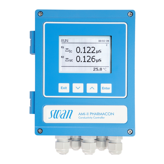
Page 31: Display
AMI-II Pharmacon Operation 5.2. Display 15:20:18 0.122 µS 0.126 µS 9.5 l/h 25.8 °C Normal operation HOLD Input active or cal delay: Instrument on hold (shows status of signal outputs). Input active: Signal outputs go to 4 mA. ERROR Non-fatal error... - Page 32 AMI-II Pharmacon Operation Switching Toggle between screens 1 and 2 using the key. between Example of screen 1: screens 15:20:18 0.122 μS 9.5 l/h 25.8 °C Example of screen 2: 15:20:18 0.122 μS 0.126 μS 9.5 l/h 25.8 °C A-96.210.561 / 060924...
-
Page 33: Software Structure
AMI-II Pharmacon Operation 5.3. Software Structure Main Menu Messages Diagnostics Maintenance Operation Installation Menu Messages 1 Messages Shows pending errors as well as the event history Pending Errors (time and state of events that have occurred at an Message List earlier point of time). -
Page 34: Changing Parameters And Values
AMI-II Pharmacon Operation 5.4. Changing Parameters and Values Changing The following example shows how to change the logger interval: parameters 1 Select the parameter you want to Sensors Logger 5.1.2 4.4.1 change. Sensor type FOME Log interval 30 min 2 Press [Enter]. -
Page 35: Data Logger
AMI-II Pharmacon Operation 5.5. Data Logger Overview The instrument has an integrated data logger. The following data is recorded: Data type Number of data Elements of each data set sets in internal buffer Event history Error messages with date, time. - Page 36 AMI-II Pharmacon Operation While the data is being written to Logger Logger the SD card, the gray background Log Interval Log Interval 30 Minutes 30 Minutes of the “Eject SD Card” menu item Clear Logger Clear Logger disappears. Eject SD Card Eject SD Card <Enter>...
-
Page 37: Maintenance
AMI-II Pharmacon Maintenance Maintenance 6.1. Maintenance Schedule As required Clean sensor. If a test resistor is available, perform a transmitter test. 6.2. Stop of Operation for Maintenance Shut off power of the instrument. A-96.210.561 / 060924... -
Page 38: Cleaning The Sensor
AMI-II Pharmacon Maintenance 6.3. Cleaning the Sensor The Swansensor Pharmacon NPT/SAN is largely maintenance free. However, depending on the application, it can be contaminated, which may cause problems. If the sensor is contaminated proceed as follows to clean the sensor. -
Page 39: Alarm Function According Usp<645
AMI-II Pharmacon Maintenance 6.4. Alarm Function According USP<645> Display Set the display to show all available conductivity values, i.e: tc: Temperature compensated conductivity uc: Uncompensated conductivity usp: Conductivity limit at given temperature Setpoint Setpoint of the USP limit can be modified from 100% to 20% (<Installation>/<Sensors>/<USP parameters>). -
Page 40: Quality Assurance Of The Instrument
AMI-II Pharmacon Maintenance 6.6. Quality Assurance of the Instrument Quality Central feature of the quality assurance function is the assignment of the monitored process to a quality assurance level. assurance There are three predefined levels and one user-defined level. By se-... -
Page 41: Connecting Sample Lines
Remaining operating time on display minimum 20 hours. – Disable temperature compensation (set to “none”) In-line instrument: AMI-II Pharmacon: – Good order and condition. Sensor surface free of deposits. – Check message list; Review the message list in menu 1.2 and check for alarms. - Page 42 AMI-II Pharmacon Maintenance Example The AMI Inspector Pharma is connected upstream to the in-line sen- sor Pharmacon at a sampling point (grab sample). AMI Inspector Pharma Sample outlet from AMI Sample line Inspector Pharma Sample inlet to AMI Inspector AMI-II Pharmacon Pharma 1 Connect the AMI Inspector Pharma to the sample line [B].
-
Page 43: Carry Out Comparison Measurement
AMI-II Pharmacon Maintenance 6.6.4 Carry Out Comparison Measurement 1 Navigate to menu Maintenance > Quality Assurance and follow the dialog on the display. 2 If the QA check is not successful, it is recommended to clean the sensor. If the QA check fails again, contact your local Swan dis- tributor for support. -
Page 44: Troubleshooting
AMI-II Pharmacon Troubleshooting Troubleshooting 7.1. Error List Two categories of messages are distinguished: Non-fatal error Non-fatal instrument error or exceeding of a programmed limit value. Such errors are marked E0xx (bold and black) in the following list. Fatal error (flashing symbol) Fatal instrument error. - Page 45 AMI-II Pharmacon Troubleshooting Error Description Corrective action – Check process. E001 Cond. Alarm high – Check programmed value. – Check process. E002 Cond. Alarm low – Check programmed value. – Check sample temperature. E007 Sample Temp. high – Check programmed value.
- Page 46 AMI-II Pharmacon Troubleshooting Error Description Corrective action – Call support. E031 Calibration Recout – Call support. E032 Wrong Frontend – None, normal status. E033 Power-on – None, normal status. E034 Power-down A-96.210.561 / 060924...
-
Page 47: Replacing Fuses
AMI-II Pharmacon Troubleshooting 7.2. Replacing Fuses When a fuse has blown, find out the cause and fix it before replace- ment. Use tweezers or needle-nosed pliers to remove the defective fuse. Use original fuses provided by Swan only. AMI-II transmitter A 0.8 AT/250V Instrument power supply... -
Page 48: Program Overview
AMI-II Pharmacon Program Overview Program Overview All menus are password-protected as soon as an administrator password has been defined. Menu 1 Messages informs about pending errors and mainte- nance tasks and shows the error history. Access by users with the authorization levels administrator, service and operator. -
Page 49: Diagnostics (Main Menu 2)
AMI-II Pharmacon Program Overview 8.2. Diagnostics (Main Menu 2) Identification * Menu numbers Designation 2.1* Version Factory Test 2.1.3.1* Motherboard 2.1.3* Front End Operating Time Years, days, hours, minutes, seconds 2.1.4.1* 2.1.4* Sensors Cond. Sensor Current Value 2.2* 2.2.1* (Raw value) -
Page 50: Maintenance (Main Menu 3)
AMI-II Pharmacon Program Overview 8.3. Maintenance (Main Menu 3) Transmitter Test 3.1.5* * Menu numbers Mount Test 3.1* (Progress) Simulation 3.2.1* Alarm Relay 3.2* 3.2.2* Relay 1 Relay 2 3.2.3* 3.2.4* Signal Output 1 3.2.5* Signal Output 2 Set Time (Date), (Time) 3.3*... -
Page 51: Installation (Main Menu 5)
AMI-II Pharmacon Program Overview 8.5. Installation (Main Menu 5) Sensors 5.1.1* * Menu numbers Flow 5.1* USP parameters 5.1.2.1* Operating Mode 5.1.2* 5.1.2.2* Limit Sensor parameters Cell Constant 5.1.3.1* 5.1.3* 5.1.3.2* Temp. Corr. 5.1.3.3* Cable length 5.1.3.4* Meas. unit Temp. Compensation Comp. -
Page 52: Output/Control
AMI-II Pharmacon Program Overview Input 5.3.4.1* * Menu numbers Active 5.3.4* 5.3.4.2* Signal Outputs 5.3.4.3* Output/Control Fault 5.3.4.4* 5.3.4.5* Delay Miscellaneous 5.4.1* Language 5.4* 5.4.2* Set defaults 5.4.3* Load Firmware Access Administrator 5.4.4.1* 5.4.4* 5.4.4.2*- 5.4.4.5* User 1-9 Sample ID 5.4.5*... -
Page 53: Program List And Explanations
AMI-II Pharmacon Program List and Explanations Program List and Explanations 1 Messages 1.1 Pending Errors 1.1.5 Provides the list of active errors with their status (active, acknowl- edged). When all active errors have been acknowledged, the alarm relay is active again. Cleared errors are moved to the message list. - Page 54 AMI-II Pharmacon Program List and Explanations 2.3 Sample 2.3.1 Sample ID: Shows the ID used to identify the location of the sample. Temperature: Shows the current sample temperature in °C. (Pt 1000): Shows the current temperature in Ohm. Sample Flow: Shows the current sample flow in l/h and the raw value in Hz.
-
Page 55: Maintenance
AMI-II Pharmacon Program List and Explanations 3 Maintenance 3.1 Transmitter Test Transmitter Test, p. 3.2 Simulation To simulate a value or a relay state, select alarm relay relay 1 and 2 signal outputs 1 and 2 signal outputs 3 and 4 (if option is installed) Change the value or state of the selected item with the arrow keys. -
Page 56: Operation
AMI-II Pharmacon Program List and Explanations 4 Operation 4.1 Sensors 4.1.1 Filter Time Constant: Used to damp noisy signals. The higher the filter time constant, the slower the system reacts to changes of the measured value. Range: 5–300 Sec 4.1.2 Hold after Cal.: Delay permitting the instrument to stabilize again... -
Page 57: Installation
AMI-II Pharmacon Program List and Explanations 5 Installation 5.1 Sensors 5.1.1 Flow: Select “Q-Flow” if a Swan flow meter is connected. Available values: Q-Flow or None 5.1.2 USP parameter: Alarm (E015) according to limits of USP <645>. 5.1.2.1 Operating Mode: Enable USP mode. Available values: off/on 5.1.2.2... - Page 58 AMI-II Pharmacon Program List and Explanations 5.2 Signal Outputs Note: The navigation in the menus Signal Output 1 and Signal Output 2 is equal. For reason of simplicity only the menu numbers of Signal Output 1 are used in the following.
- Page 59 AMI-II Pharmacon Program List and Explanations As process The process value can be represented in three ways: linear, bilinear or logarithmic. See graphs below. values [mA] 0 / 4 Linear X Measured value Bilinear [mA] 0 / 4 1’000 10’000 X Measured value (logarithmic) A-96.210.561 / 060924...
- Page 60 AMI-II Pharmacon Program List and Explanations 5.2.1.40 Scaling: Enter beginning and end point (range low and high) of the linear or logarithmic scale. In addition, the midpoint for the bilinear scale. Parameter Conductivity: 5.2.1.40.10 Range low: 0 µS–300 mS 5.2.1.40.20 Range high: 0 µS–300 mS...
- Page 61 AMI-II Pharmacon Program List and Explanations Response to maximum control output = 1.2/a Tangent on the inflection point = 2L Time = L/2 The point of intersection of the tangent with the respective axis will result in the parameters a and L.
- Page 62 AMI-II Pharmacon Program List and Explanations 5.2.1.43 Control Parameters: if Parameters = Cond. uc. 5.2.1.43.13 Setpoint Range: 0 µS–300 mS 5.2.1.43.23 P-Band: Range: 0 µS–300 mS 5.2.1.43.3 Reset time: The reset time is the time till the step response of a sin- gle I-controller will reach the same value as it will be suddenly reached by a P-controller.
- Page 63 AMI-II Pharmacon Program List and Explanations 5.3.1.1 Alarm Conductivity 5.3.1.1.1 Alarm High: If the measured value rises above the alarm high value, the alarm relay is activated and E001 is displayed in the message list. Range: 0.000 µS –300 mS 5.3.1.1.25...
- Page 64 AMI-II Pharmacon Program List and Explanations 5.3.1.5 Case Temp. low: Set the alarm low value for temperature of electron- ics housing. If the value falls below the programmed value E014 is issued. Range: -10 to +20 °C 5.3.2 and 5.3.3 Relay 1 and 2: The function of relay contacts 1 or 2 is defined by the user.
- Page 65 AMI-II Pharmacon Program List and Explanations 5.3.2.50 Delay: Time by which the switching of the alarm relay is delayed after the measured value has risen above or fallen below the pro- grammed alarm. Range. 0–600 Sec 5.3.2.1 Function = Control upwards/downwards: The relays can be used to drive control units such as solenoid valves or membrane dosing pumps.
- Page 66 AMI-II Pharmacon Program List and Explanations 5.3.2.24 Interval 5.3.2.340 Interval: The interval can be programmed within a range of 1–1’440 min. 5.3.2.44 Run Time: Enter the time the relay stays active. Range: 5–32’400 sec. 5.3.2.54 Delay: during run time plus the delay time the signal and control out- puts are held in the operating mode programmed below.
- Page 67 AMI-II Pharmacon Program List and Explanations 5.3.2.24 weekly The relay contact can be activated at one or several days of a week. The daily starting time is valid for all days. 5.3.2.342 Calendar: 5.3.2.342.1 Start time: The programmed start time is valid for each of the pro- grammed days.
- Page 68 AMI-II Pharmacon Program List and Explanations 5.3.4.4 Fault: No message is issued in pending error list and the alarm relay does not switch when input is active. Message E024 is stored in the message list. Message E024 is issued and stored in the message Yes: list.
- Page 69 AMI-II Pharmacon Program List and Explanations 5.4.4.2 User 1 5.4.4.2.1 Name: Enter the name of the user. 5.4.4.2.2 Function: Function Administrator Service Operator Administrator: Access to all menus. Only an administrator can assign user rights and passwords to users 1 to 9.
- Page 70 AMI-II Pharmacon Program List and Explanations 5.5 Interface Select one of the following communication protocols. Depending on your selection, different parameters must be defined. 5.5.1 Protocol: Profibus 5.5.20 Device address: Range: 0–126 5.5.30 ID no.: Range: Analyzer; Manufacturer; Multivariable 5.5.40...
-
Page 71: Default Values
AMI-II Pharmacon Default Values Default Values Operation Sensors Filter Time Const.:................ 10 s Hold after Cal.:................300 s Alarm Relay .................same as in Installation Signal Output .................same as in Installation Relay 1/2 .................same as in Installation Input .................same as in Installation Logger Logger Interval:............... - Page 72 AMI-II Pharmacon Default Values Case temp. high: ............... 65 °C Case temp. low:................0 °C Relay 1/2 Function:................Limit upper Parameter:...............Conductivity Setpoint: ................... 30 mS Hysteresis:................10.0 µS Delay: ...................30 s If Function = Control upw. or dnw: Parameter:...............Conductivity Settings: Actuator: ............Frequency Settings: Pulse Frequency: ..........120/min...
- Page 73 AMI-II Pharmacon A-96.210.561 / 060924...
- Page 74 Swan Products - Analytical Instruments for: Swan is represented worldwide by subsidiary companies and distributors and cooperates with independent representatives all over the world. For contact in- formation, please scan the QR code. Swan Analytical Instruments ∙ CH-8340 Hinwil www.swan.ch ∙ swan@swan.ch AMI-II Pharmacon...
Need help?
Do you have a question about the AMI-II Pharmacon and is the answer not in the manual?
Questions and answers