
Related Manuals for Swann AMU-II Pharmacon


Summary of Contents for Swann AMU-II Pharmacon
- Page 1 A-96.150.691 / 041021 Operator’s Manual Firmware V1.00 and higher AMU-II Pharmacon...
- Page 2 Swan Analytische Instrumente AG Studbachstrasse 13 8340 Hinwil Switzerland Internet: www.swan.ch E-mail: support@swan.ch Document Status AMU-II Pharmacon Operator’s Manual Title: A-96.150.691 Revision Issue Oct. 2021 First edition © 2021, Swan Analytische Instrumente AG, Switzerland, all rights reserved. The information contained in this document is subject to change without notice.
-
Page 3: Table Of Contents
2.2.1 AMU-II Pharmacon Transmitter ........11 2.2.2... - Page 4 AMU-II Pharmacon Maintenance ........... 37 6.1.
-
Page 5: Safety Instructions
AMU-II Pharmacon Safety Instructions Operator’s Manual This document describes the main steps for instrument setup, operation and maintenance. Safety Instructions General The instructions included in this section explain the potential risks associated with instrument operation and provide important safety practices designed to minimize these risks. -
Page 6: Warning Notices
AMU-II Pharmacon Safety Instructions 1.1. Warning Notices The symbols used for safety-related notices have the following meaning: DANGER Your life or physical wellbeing are in serious danger if such warn- ings are ignored. Follow the prevention instructions carefully. WARNING Severe injuries or damage to the equipment can occur if such warnings are ignored. - Page 7 AMU-II Pharmacon Safety Instructions Warning Signs The warning signs in this manual have the following meaning: Electrical shock hazard Corrosive Harmful to health Flammable Warning general Attention general A-96.150.691 / 041021...
-
Page 8: General Safety Regulations
AMU-II Pharmacon Safety Instructions 1.2. General Safety Regulations Legal The user is responsible for proper system operation. All precautions must be followed to ensure safe operation of the instrument. Requirements Spare Use only official Swan spare parts and disposables. If other parts are used during the normal warranty period, the manufacturer’s warranty... -
Page 9: Product Description
The conductivity is a parameter for the total quantity of ions present in the solution. range The AMU-II Pharmacon transmitter is used together with the two- electrode inline sensors Pharmacon NPT or Pharmacon SAN for applications in purified water (PW) ... - Page 10 AMU-II Pharmacon Product Description Alarm relays Two potential-free contacts (one normally open and one normally closed). Summary alarm indication for programmable alarm values and instrument faults. Normally open contact: closed during normal operation, open on error and power loss.
-
Page 11: Single Components
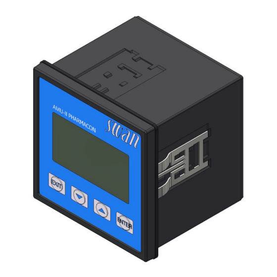
AMU-II Pharmacon Product Description 2.2. Single Components 2.2.1 AMU-II Pharmacon Transmitter ® General Electronics housing: Noryl resin Protection degree: up to IP54 (front) Ambient temperature: -10 to +50 °C Humidity: 10–90% rel., non condensing Display: backlit LCD, 75 x 45 mm... -
Page 12: Swansensor Pharmacon
AMU-II Pharmacon Product Description 2.2.2 Swansensor Pharmacon Two-electrode conductivity sensor for the inline measurement of purified water and water for injection. Available in two different models: Swansensor Pharmacon SAN, with sanitary flange Swansensor Pharmacon NPT, with NPT ¾” thread Swansensor Polished surface, no dead volume. - Page 13 AMU-II Pharmacon Product Description Dimensions Total length: 153 mm Insertion length: 85 mm dia. 24 mm / (0,95 in) dia. 50.5 mm / (1 1/2“) dia. 16 mm / (0,63 in) A-96.150.691 / 041021...
- Page 14 AMU-II Pharmacon Product Description Swansensor Polished surface, no dead volume. Equipped with fixed cable (~30cm, PTFE) with M16 male plug. Pharmacon The sensor is accompanied with the following certificates: Cell constant Material specification Inspection certificate according to EN 10204 (surface roughness with SS Pharmacon NPT).
- Page 15 AMU-II Pharmacon Product Description Dimensions Total length: 102 mm Insertion length: 29 mm SW 28 mm / 1,26 in 9 mm / 0.35 in 3/4 NPT 29 mm / 1.14 in dia. 12.7 mm / 0.5 in A-96.150.691 / 041021...
-
Page 16: Installation
AMU-II Pharmacon Installation Installation 3.1. Mounting of the AMU-II Transmitter Transmitter 96.0 mm / 3.78" dimensions 85.0 mm / 3.35" 78.0 mm / 3.07" A-96.150.691 / 041021... - Page 17 AMU-II Pharmacon Installation Cutout 92 mm / 3.62" dimensions A-96.150.691 / 041021...
-
Page 18: Electrical Connections
AMU-II Pharmacon Installation 3.2. Electrical Connections Connection diagram CAUTION Use only the terminals shown in this diagram, and only for the mentioned purpose. Use of any other terminals will cause short circuits with possible corresponding consequences to material and personnel. -
Page 19: Power Supply
Mains cable according to standards IEC 60227 or IEC 60245; flammability rating FV1 Mains equipped with an external switch or circuit-breaker – near the instrument – easily accessible to the operator – marked as interrupter for AMU-II Pharmacon 3.4. Sensor Terminals: see Connection diagram, p. -
Page 20: Input
AMU-II Pharmacon Installation 3.6. Input Note: Use only potential-free (dry) contacts. Terminals 16/8 For programming see Program List and Explanations, p. 3.7. Relay Contacts 3.7.1 Alarm Relay Note: Max. load 100 mA/50 V Alarm output for system errors. For error codes see Error List, p. -
Page 21: Signal Output 1 And 2 (Current Outputs)
AMU-II Pharmacon Installation 3.8. Signal Output 1 and 2 (Current Outputs) Note: Max. burden 510 Ω If signals are sent to two different receivers, use signal isolator (loop isolator). Signal output 1: Terminals 12 (+) and 11 (-) Signal output 2: Terminals 13 (+) and 11 (-) For programming see Program List and Explanations, p. -
Page 22: Interface Options
AMU-II Pharmacon Installation 3.9. Interface Options The functionality of the AMU-II Pharmacon can be expanded with one of the following interface options: RS485 with Modbus or Profibus protocol HART USB 3.9.1 Installation WARNING Electrical shock hazard Before opening the housing, disconnect the AMU-II transmitter from the power supply. - Page 23 AMU-II Pharmacon Installation To install an interface option, proceed as follows: 1 Switch power off. 2 Loosen the four screws at the back of the AMU-II transmitter and remove the backplate. 3 Pull the mainboard [B] completely out of the housing.
-
Page 24: Usb Option
AMU-II Pharmacon Installation 3.9.2 USB Option C USB stick Pushbutton Blue LED Menu item Calling up the <Operation>/<Eject USB Stick> menu item performs the following actions: the calibration history and the event history are copied to the USB stick, ... -
Page 25: Rs485 Option
AMU-II Pharmacon Installation 3.9.3 RS485 Option Menu items After the RS485 option has been installed, the <Installation>/ <Interface> menu item becomes visible. Select Modbus RTU or Profibus as protocol. Terminating On the last RS485 interface in the network, move the switch to the position marked “Ron”... -
Page 26: 3.10. Rs232 Interface
AMU-II Pharmacon Installation 3.10. RS232 Interface The RS232 interface is located on the back of the AMU-II transmitter. Use the USB to RS232 interface converter available from Swan. Downloading To use the functions provided via the RS232 interface, the SwanTerminal program is required, which can be downloaded from SwanTerminal www.swan.ch. -
Page 27: 3.11. Install The Swansensor Pharmacon San
AMU-II Pharmacon Installation 3.11. Install the Swansensor Pharmacon SAN Swansensor Pharmacon SAN Clamp Gasket T-Pipe Pipe To install the Swansensor Pharmacon SAN into a pipe flange pro- ceed as follows: 1 Make sure that the surface of the T-Piece flange [D] is clean. - Page 28 AMU-II Pharmacon Installation Recommended Installation The flow direction should be towards the sensor tip. This avoids air or solids becoming trapped in the sensor. Vertical installation is pos- sible if the pipe is always full and no air can be trapped between the electrodes.
-
Page 29: 3.12. Install The Swansensor Pharmacon Npt
AMU-II Pharmacon Installation 3.12. Install the Swansensor Pharmacon NPT Teflon tape Swansensor Pharmacon NPT Flange To install the Swansensor Pharmacon NPT into a pipe flange pro- ceed as follows: 1 Wrap 7 turns of teflon tape around the sensor thread. - Page 30 AMU-II Pharmacon Installation Recommended Installation The flow direction should be towards the sensor tip. This avoids air or solids becoming trapped in the sensor. Vertical installation is pos- B C D E sible if the pipe is always full and no air can be trapped between the electrodes.
-
Page 31: Instrument Setup
AMU-II Pharmacon Instrument Setup Instrument Setup 1 Switch on power. 2 Let the instrument run-in for 1 h. 4.1. Programming Menu 5.1.2 (activate if required) parameters Set Operating mode to ON Set the Limit according your requirements. Sensor Program all sensor parameters in Menu 5.1.3 <Installation>/<Sensors>/<Sensor parameters>:... - Page 32 AMU-II Pharmacon Instrument Setup Temp. Menu 5.1.4 Compensation Choose between: none Coefficient Neutral salts High-purity water Strong acids Strong bases Ammonia, Ethanolamine Morpholine Quality Menu 5.1.5 (Activate if required). assurance Set the Level according to your requirements, details see Quality As- surance of the Instrument, p.
-
Page 33: Operation
AMU-II Pharmacon Operation Operation 5.1. Keys to exit a menu or command (rejecting any changes) to move back to the previous menu level to move DOWN in a menu list and to decrease digits to move UP in a menu list and to increase digits... -
Page 34: Display
AMU-II Pharmacon Operation 5.2. Display 15:20:18 0.178 μS 0.092 μS 9.5 l/h 25.4°C A RUN normal operation HOLD input closed or cal delay: Instrument on hold (shows status of signal outputs). input closed: control/limit is interrupted (shows status of signal outputs). -
Page 35: Software Structure
AMU-II Pharmacon Operation 5.3. Software Structure Main Menu Messages Diagnostics Maintenance Operation Installation Menu Messages 1 Messages Reveals pending errors as well as an event history Pending Errors (time and state of events that have occurred at an Message List earlier point of time). -
Page 36: Changing Parameters And Values
AMU-II Pharmacon Operation 5.4. Changing Parameters and values Changing The following example shows how to set the Q-Flow sensor: parameters 1 Select the parameter you want to Sensors 5.1.1 change. Flow None 2 Press <Enter> Sensor parameters Temp. Compensation Quality Assurance... -
Page 37: Maintenance
AMU-II Pharmacon Maintenance Maintenance 6.1. Maintenance Schedule As required Clean sensor. If a test resistor is available, perform a transmitter test. 6.2. Stop of Operation for Maintenance Shut off power of the instrument. A-96.150.691 / 041021... -
Page 38: Cleaning The Sensor
AMU-II Pharmacon Maintenance 6.3. Cleaning the Sensor The Swansensor Pharmacon NPT/SAN is largely maintenance free. Depending on the application, however, the sensor may become contaminated, which can lead to problems. If the sensor is contaminated proceed as follows to clean the sensor. -
Page 39: Alarm Function According To Usp<645
AMU-II Pharmacon Maintenance 6.4. Alarm Function According to USP<645> Display Set the display to show all available conductivity values, i.e: tc: Temperature compensated conductivity uc: Uncompensated conductivity usp: Conductivity Limit at given temperature The setpoint of the USP limit can be modified from 100% to 20% (<Installation>/<Sensors>/<USP parameters>). -
Page 40: Quality Assurance Of The Instrument
Every SWAN on-line instrument is equipped with integrated, autono- mous quality assurance functions to survey the plausibility of each measurement. For AMU-II Pharmacon these are: continuous monitoring of the temperature inside the transmitter case. periodic accuracy test with ultra high precision resistors Further a manual, menu driven inspection procedure can be carried out using a certified reference instrument. - Page 41 AMU-II Pharmacon Maintenance Tab. 8-1 Limits and interval for AMU-II Pharmacon max. deviation max. deviation min. inspection Quality Level temperature [°C] result [%] interval 0: Off 0.5 °C 10.0 % 1: Trend annual 0.4 °C 5.0 % 2: Standard quarterly 0.3 °C...
-
Page 42: Activate Swan Quality Assurance Procedure
AMU-II Pharmacon Maintenance 6.6.1 Activate SWAN Quality Assurance Procedure Enable quality assurance procedure at each instrument by selecting the quality level in menu 5.1.5, p. 58, Quality Assurance <Installation>/<Sensors>. The corresponding submenus are then activated. Note: The activation is necessary the first time only. - Page 43 AMU-II Pharmacon Maintenance Example: The reference instrument, AMI Inspector Pharmacon, is connected up-stream to the in-line sensor Pharmacon at a sampling point (grab sampling via sample). sampling point Reference instrument Sample outlet from reference Sample line instrument Sample inlet to reference...
-
Page 44: Carry Out Comparison Measurement
AMU-II Pharmacon Maintenance 6.6.4 Carry Out Comparison Measurement 1 Navigate to menu <Maintenance>/<Quality Assurance>. 2 Press [Enter]. 3 Follow the dialog on the Display. 4 Carry out pre test preparations Con- Quality Assurance 3.4.5 nect instruments. - carry out preparations... -
Page 45: Completion Of The Measurement
AMU-II Pharmacon Maintenance 6.6.5 Completion of the Measurement 1 Close the flow regulating valve of the AMI Inspector. 2 Disconnect the AMI Inspector by removing the tubes. 3 Shut down the AMI Inspector. 6.7. Longer Stop of Operation Shut off power of the instrument. -
Page 46: Error List
AMU-II Pharmacon Error List Error List Error Non-fatal Error. Indicates an alarm if a programmed value is exceeded. Such Errors are marked E0xx. Fatal Error (blinking symbol) Control of dosing devices is interrupted. The indicated measured values are possibly incorrect. - Page 47 AMU-II Pharmacon Error List Error Description Corrective action – check process E001 Cond. Alarm high – check program value 5.3.1.1, p. 63 – check process E002 Cond. Alarm low – check program value 5.3.1.1, p. 63 – check sample temperature E007 Sample Temp.
- Page 48 AMU-II Pharmacon Error List Error Description Corrective action – See If Fault Yes is programmed in Menu E024 Input active 5.3.4, p. 68 – call service E026 IC LM75 – call service E030 EEprom Frontend – call service E031 Calibration Recout –...
-
Page 49: Program Overview
AMU-II Pharmacon Program Overview Program Overview For explanations about each parameter of the menus see Program List and Explanations, p. Menu 1 Messages informs about pending errors and mainte- nance tasks and shows the error history. Password protection possible. No settings can be modified. -
Page 50: Diagnostics (Main Menu 2)
AMU-II Pharmacon Program Overview 8.2. Diagnostics (Main Menu 2) Identification Designation * Menu numbers AMU-II Pharmacon 2.1* Version V6.21 – 05/18 Factory Test 2.1.3.1* Instrument 2.1.3* Motherboard Front End Operating Time 2.1.4.1* Years / Days / Hours / Minutes / Seconds 2.1.4*... -
Page 51: Maintenance (Main Menu 3)
AMU-II Pharmacon Program Overview 8.3. Maintenance (Main Menu 3) Transmitter Test 3.1.5* * Menu numbers Mount Test 3.1* (Progress) Simulation 3.2.1* Alarm Relay 3.2* 3.2.2* Relay 1 3.2.3* Relay 2 3.2.4* Signal Output 1 Signal Output 2 3.2.5* Set Time (Date), (Time) 3.3*... -
Page 52: Installation (Main Menu 5)
AMU-II Pharmacon Program Overview 8.5. Installation (Main Menu 5) Sensors 5.1.1* * Menu numbers Flow USP parameters 5.1* Operating Mode 5.1.2.1* 5.1.2* 5.1.2.2* Limit Sensor parameters 5.1.3.1* Cell Constant 5.1.3* 5.1.3.2* Temp. Corr. 5.1.3.3* Cable length Meas. unit 5.1.3.4* Temp. Compensation Comp. -
Page 53: Delay
AMU-II Pharmacon Program Overview Input 5.3.4.1* * Menu numbers Active 5.3.4* 5.3.4.2* Signal Outputs 5.3.4.3* Output/Control Fault 5.3.4.4* 5.3.4.5* Delay Miscellaneous 5.4.1* Language 5.4* 5.4.2* Set defaults 5.4.3* Load Firmware Access Administrator 5.4.4.1* 5.4.4* 5.4.4.2*- 5.4.4.5* User 1-4 Sample ID 5.4.5*... -
Page 54: Program List And Explanations
AMU-II Pharmacon Program List and Explanations Program List and Explanations 1 Messages 1.1 Pending Errors 1.1.5 Provides the list of active errors with their status (active, acknowl- edged). If an active error is acknowledged, the alarm relay opens again. Cleared errors are moved to the Message list. - Page 55 AMU-II Pharmacon Program List and Explanations 2.2.1.5 QA History: Review QA values (Number, Date, Time, Deviation Conductivity, Deviation Temperature, Status of QA check) of the last quality assurance procedures. 2.2.2 Miscellaneous: 2.2.2.1 Case Temp: Shows the actual temperature [°C] inside the transmit- ter.
-
Page 56: Maintenance
AMU-II Pharmacon Program List and Explanations 3 Maintenance 3.1 Transmitter Test 3.1.5 Follow the commands on the screen. Transmitter Test, p. 39 3.2 Simulation To simulate a value or a relay state, select alarm relay, relay 1/2, signal output 1/2... -
Page 57: Installation
AMU-II Pharmacon Program List and Explanations 4.2 Relay Contacts 5.3 Relay Contacts, p. 62 4.3 Logger The instrument is equipped with an internal logger. The logger data can be downloaded to a PC using the built-in RS232 interface. The logger can save approx. 1500 data records. Records consist of: Date, time, alarms, measured value, measured value uncompensat- ed, temperature, flow. -
Page 58: 5.2 Signal Outputs
AMU-II Pharmacon Program List and Explanations 5.1.3 Sensor parameters: 5.1.3.1 Cell Constant: Enter the cell constant (ZK). It is printed on the label of the used sensor. Range: 0.005000–11.00 cm 5.1.3.2 Temperature Correction: Enter the temperature correction (DT). It is printed on the label of the used sensor. - Page 59 AMU-II Pharmacon Program List and Explanations 5.2.1.3-5.2.2.3 Function: Define if the signal output is used to transmit a process val- ue or to drive a control unit. Available functions are: Linear, bilinear or logarithmic for process values. As process values, p. 59 ...
- Page 60 AMU-II Pharmacon Program List and Explanations 5.2.x.40 Scaling: Enter beginning and end point (Range low & high) of the linear or logarithmic scale. In addition, the midpoint for the bilinear scale. Parameter Conductivity: 5.2.1.40.10 Range low: 0 µS–300 mS 5.2.1.40.20 Range high: 0 µS–300 mS...
- Page 61 AMU-II Pharmacon Program List and Explanations Ziegler-Nichols method for the optimization of a PID controller: Response to maximum control output = 1.2/a Tangent on the inflection point = 2L Time = L/2 The point of intersection of the tangent with the respective axis will result in the parameters a and L.
- Page 62 AMU-II Pharmacon Program List and Explanations 5.2.1.43 Control Parameters: if Parameters = Sample flow 5.2.1.43.12 Setpoint Range: 0 –50 l/h 5.2.1.43.22 P-Band: Range: 0 –50 l/h 5.2.1.43 Control Parameters: if Parameters = Cond. uc. 5.2.1.43.13 Setpoint Range: 0 S–300 mS 5.2.1.43.23...
- Page 63 AMU-II Pharmacon Program List and Explanations Program alarm levels, hysteresis values and delay times for the fol- lowing parameters. Alarm Conductivity Sample Flow Sample Temp. Case Temp. high Case Temp. low 5.3.1.1 Alarm Conductivity 5.3.1.1.1...
- Page 64 AMU-II Pharmacon Program List and Explanations 5.3.1.3 Sample temperature: Define the measuring value, which should issue an alarm high respectively low. 5.3.1.3.1 Alarm High: If the sample temperature rises above the programmed value E007 is issued. Range: 30–200 °C 5.3.1.3.x Alarm Low: If the sample temperature falls below the programmed value E008 is issued.
- Page 65 AMU-II Pharmacon Program List and Explanations 5.3.2.1 Function = Limit upper/lower: When the relays are used as upper or lower limit switches, program the following: 5.3.2.20 Parameter: select a process value 5.3.2.300 Setpoint: If the measured value rises above respectively falls below the set-point, the relay is activated.
- Page 66 AMU-II Pharmacon Program List and Explanations 5.3.2.32 Settings: Choose the respective actuator: Time proportional Frequency Motor valve 5.3.2.32.1 Actuator = Time proportional Examples of metering devices that are driven time proportional are solenoid valves, peristaltic pumps. Dosing is controlled by the operating time.
- Page 67 AMU-II Pharmacon Program List and Explanations 5.3.2.24 Mode: Operating mode (interval, daily, weekly) 5.3.2.24 Interval 5.3.2.340 Interval: The interval can be programmed within a range of 1–1440 min. 5.3.2.44 Run Time: Enter the time the relay stays closed. Range: 5–6000 sec.
- Page 68 AMU-II Pharmacon Program List and Explanations 5.3.2.7 Output/Control: see Interval 5.3.2.24 weekly The relay contact can be closed at one or several days, of a week. The daily starting time is valid for all days. 5.3.2.342 Calendar: 5.3.2.342.1 Start time: The programmed start time is valid for each of the pro- grammed days.
-
Page 69: Output/Control
AMU-II Pharmacon Program List and Explanations 5.3.4.3 Output/Control: (relay or signal output): Controller continues normally. Cont. Controller continues on the last valid value. Hold Controller is switched off. 5.3.4.4 Fault: No message is issued in pending error list and the alarm relay does not close when input is active. - Page 70 AMU-II Pharmacon Program List and Explanations 5.4.4.1 Administrator: The administrator owns all rights and has access to all menus. Only an administrator can assign user rights for the users 1 to 4. Name: Admin predefined, not changeable Function: Administrator predefined, not changeable 5.4.4.1.3...
- Page 71 AMU-II Pharmacon Program List and Explanations 5.5 Interface Select one of the following communication protocols. Depending on your selection, different parameters must be defined. 5.5.1 Protocol: Profibus 5.5.20 Device address: Range: 0–126 5.5.30 ID No.: Range: Analyzer; Manufacturer; Multivariable 5.5.40...
-
Page 72: Default Values
AMU-II Pharmacon Default Values Default Values Operation: Sensors Filter Time Const.: ................10 s Hold after Cal.:................300 s Alarm Relay .................same as in Installation Signal Output .................same as in Installation Relay 1/2 .................same as in Installation Input .................same as in Installation Logger Logger Interval:................ - Page 73 AMU-II Pharmacon Default Values Case temp. high:................ 65 °C Case temp. low: ................0 °C Relay 1/2 Function: ................Limit upper Parameter: ...............Conductivity Setpoint:..................30 mS Hysteresis: ................10.0 µS Delay:................... 30 s If Function = Control upw. or dnw: Parameter: ...............Conductivity Settings: Actuator: .............
-
Page 74: Notes
AMU-II Pharmacon Notes Notes A-96.150.691 / 041021... - Page 75 AMU-II Pharmacon Notes A-96.150.691 / 041021...
- Page 76 Swan Products - Analytical Instruments for: Swan is represented worldwide by subsidiary companies and distributors and cooperates with independent representatives all over the world. For contact in- formation, please scan the QR code. Swan Analytical Instruments ∙ CH-8340 Hinwil www.swan.ch ∙ swan@swan.ch AMU-II Pharmacon...
Need help?
Do you have a question about the AMU-II Pharmacon and is the answer not in the manual?
Questions and answers