Table of Contents
Advertisement
Quick Links
Advertisement
Table of Contents

Related Manuals for Swann AMU Pharmacon


Summary of Contents for Swann AMU Pharmacon
- Page 1 AMU Pharmacon Version 6.21 and higher A-96.250.691 / 230320...
- Page 2 For any technical question, contact your nearest SWAN representative, or the manufacturer: SWAN ANALYTISCHE INSTRUMENTE AG Studbachstrasse 13 8340 Hinwil Switzerland Internet: www.swan.ch E-mail: support@swan.ch Document Status AMU Pharmacon Operator’s Manual Title: A-96.250.691 Revision Issue April 2013 First edition July 2019 Update to firmware V6.21 ©...
-
Page 3: Table Of Contents
Single Components ........2.2.1 Transmitter AMU Pharmacon ......2.2.2 Swansensor Pharmacon . - Page 4 AMU Pharmacon Maintenance ........
-
Page 5: Safety Instructions
AMU Pharmacon Safety Instructions AMU Pharmacon - Operator’s Manual This document describes the main steps for instrument setup, oper- ation and maintenance. Safety Instructions General The instructions included in this section explain the potential risks associated with instrument operation and provide important safety practices designed to minimize these risks. -
Page 6: Warning Notices
AMU Pharmacon Safety Instructions 1.1. Warning Notices The symbols used for safety-related notices have the following sig- nificance: DANGER Severe injuries or death will result if such warnings are ignored. Follow the prevention instructions carefully. WARNING Severe injuries or damage to the equipment can occur if such warnings are ignored. - Page 7 AMU Pharmacon Safety Instructions Warning Signs The importance of the warning signs in this manual. Electrical shock hazard Corrosive Harmful to health Flammable Warning general Attention general A-96.250.691 / 230320...
-
Page 8: General Safety Regulations
AMU Pharmacon Safety Instructions 1.2. General Safety Regulations Legal The user is responsible for proper system operation. All precautions must be followed to ensure safe operation Requirements of the instrument. Spare Parts Use only official SWAN spare parts and disposables. If other parts are used during the normal warranty period, the manufacturer’s... -
Page 9: Product Description
The conductivity is a parameter for the total quantity of ions present in the solution. range The AMU Pharmacon transmitter together with the two-electrode In-line sensor Pharmacon NPT or Pharmacon SAN is used for ap- plications in: purified water (PW) ... - Page 10 AMU Pharmacon Product Description Measurement The compensated- (tc), the uncompensated value (uc) and the ac- tual USP alarm value can be displayed. value USP<645> Alarm function for limit values according to USP<645> Stage 1. By editing the Limit (100% to 20%) an action limit can be set.
-
Page 11: Single Components
Product Description 2.2. Single Components 2.2.1 Transmitter AMU Pharmacon The AMU measuring and control transmitter is used for panel in- stallation. It has connections for a two-electrode conductivity sen- sor with a built-in Pt1000 temperature probe, e.g. Swansensor Pharmacon SAN, and for a digital sample flow meter. -
Page 12: Swansensor Pharmacon
AMU Pharmacon Product Description 2.2.2 Swansensor Pharmacon Two-electrode conductivity sensor for the inline measurement of purified water and water for injection of pharmaceutical water. Available in two different models: Swansensor Pharmacon SAN, with sanitary flange Swansensor Pharmacon NPT, with NPT ¾” thread Swansensor Polished surface, no dead volume. - Page 13 AMU Pharmacon Product Description Dimensions Total length: 153 mm Insertion length: 85 mm dia. 24 mm / (0,95 in) dia. 50.5 mm / (1 1/2“) dia. 16 mm / (0,63 in) A-96.250.691 / 230320...
- Page 14 AMU Pharmacon Product Description Swansensor Polished surface, no dead volume. Equipped with fixed cable (~30cm, PTFE) with M16 male plug. Pharmacon Sensor will be accompanied with following certificates: Cell constant, Material specification Inspection certificate according to EN 10204 (surface roughness with SS Pharmacon NPT).
- Page 15 AMU Pharmacon Product Description Dimensions Total length: 102 mm Insertion length: 29 mm SW 28 mm / 1,26 in 9 mm / 0.35 in 3/4 NPT 29 mm / 1.14 in dia. 12.7 mm / 0.5 in A-96.250.691 / 230320...
-
Page 16: Installation
AMU Pharmacon Installation Installation 3.1. Installation Check List Check Instrument’s specification must conform to your power ratings. Do not switch on power until all external devices are connected. Installation The transmitter is intended for panel mounting. The dimensions are shown in Dimensions of the AMU Transmitter, p. -
Page 17: Dimensions Of The Amu Transmitter
AMU Pharmacon Installation 3.2. Dimensions of the AMU Transmitter A-96.250.691 / 230320... -
Page 18: Install The Swansensor Pharmacon San
AMU Pharmacon Installation 3.3. Install the Swansensor Pharmacon SAN Swansensor Pharmacon SAN Clamp Gasket T-Pipe Pipe To install the Swansensor Pharmacon SAN into a pipe flange pro- ceed as follows: 1 Make sure, that the surface of the T-Piece flange [D] is clean. - Page 19 AMU Pharmacon Installation Recommended Installation The flow direction should be towards the sensor tip. This avoids air or solids becoming trapped in the sensor. Vertical installation is possible if the pipe is always full and no air can be trapped between the electrodes.
-
Page 20: Install The Swansensor Pharmacon Npt
AMU Pharmacon Installation 3.4. Install the Swansensor Pharmacon NPT Teflon tape Swansensor Pharmacon NPT Flange To install the Swansensor Pharmacon NPT into a pipe flange pro- ceed as follows: 1 Wrap 7 turns of teflon tape around the sensor thread. - Page 21 AMU Pharmacon Installation Recommended Installation The flow direction should be towards the sensor tip. This avoids air or solids becoming trapped in the sensor. Vertical installation is B C D E possible if the pipe is always full and no air can be trapped between the electrodes.
-
Page 22: Connection Diagram
AMU Pharmacon Installation 3.5. Connection Diagram CAUTION Use only the terminals shown in this diagram, and only for the mentioned purpose. Use of any other terminals will cause short circuits with possible corresponding consequences to material and personnel. A-96.250.691 / 230320... - Page 23 AMU Pharmacon Installation Rear view AMU Transmitter (+) (-) 2 3 4 5 6 7 8 9 10 11 12 13 14 RS232 RON OFF A/PB B/PB A-96.250.691 / 230320...
-
Page 24: Power Supply
AMU Pharmacon Installation 3.6. Power supply CAUTION Do not apply power to the transmitter until all electrical connec- tions are made. Power supply connector Phase conductor Neutral conductor Installation The installation must meet the following requirements: requirements Mains cable to comply with standards IEC 60227 or IEC 60245;... -
Page 25: Relay Contacts
AMU Pharmacon Installation 3.10. Relay Contacts 3.10.1 Alarm Relay NOTICE: Max. load 100 mA/50 V Alarm output for system errors. Error codes see Error List, p. Terminals Description Opened during normal operation. Closed on error and loss of power. Normally Closed Closed during normal operation. -
Page 26: Interfaces
AMU Pharmacon Installation 3.12. Interfaces 3.12.1 RS232 Interface The interface RS232 is on the backside of the AMU transmitter. The AMU Interface RS232 PCB is used for Logger down load and Firmware up load. For detailed information see the corresponding manual “AMU RS232 Interface”. -
Page 27: Modbus (Optional)
AMU Pharmacon Installation 3.12.3 Modbus (optional) To connect several instruments by means of a network consult the MODBUS manual. Use appropriate network cable. NOTICE: The switch must be ON, if only one instrument is installed, or on the last instrument in the bus... -
Page 28: Instrument Setup
AMU Pharmacon Instrument Setup Instrument Setup 1 Switch on power. 2 Let the instrument run-in for 1 h. 4.1. Programming Menu 5.1.2 (activate if required) Parameters Set Operating mode to ON Set the Limit according your requirements. Sensor Program all sensor parameters in Menu 5.1.3 <Installation>... - Page 29 AMU Pharmacon Instrument Setup Temp. Menu 5.1.4 Compensation Choose between: none Coefficient Neutral salts High-purity water Strong acids Strong bases Ammonia, Ethanolamine Morpholine External Program all parameters for external devices (interface, recorders, etc.) See program list and explanations...
-
Page 30: Operation
AMU Pharmacon Operation Operation 5.1. Keys Exit Enter to exit a menu or command (rejecting any changes) to move back to the previous menu level to move DOWN in a menu list and to decrease digits to move UP in a menu list and to increase digits... -
Page 31: Display
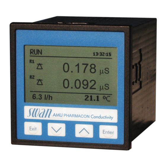
AMU Pharmacon Operation 5.2. Display 15:20:18 0.178 µS 0.092 µS 9.5 l/h 21.8°C normal operation HOLD input closed or cal delay: Instrument on hold (shows status of signal outputs). input closed: control/limit is interrupted (shows status of signal outputs). ERROR... -
Page 32: Software Structure
AMU Pharmacon Operation 5.3. Software Structure Main Menu Messages Diagnostics Maintenance Operation Installation Menu Messages 1 Messages Reveals pending errors as well as an event history Pending Errors (time and state of events that have occurred at an Message List earlier point of time). -
Page 33: Changing Parameters And Values
AMU Pharmacon Operation 5.4. Changing Parameters and values Changing The following example shows how to set the Q-Flow sensor: parameters 1 Select the parameter you want to Sensors 5.1.1 change. Flow None 2 Press <Enter> Sensor parameters Temp. Compensation Quality Assurance... -
Page 34: Maintenance
AMU Pharmacon Maintenance Maintenance This section describes the activities intended to retain the instru- ment in, or to restore it to a state in which it maintains the required or specified performance. 6.1. Maintenance Schedule WARNING Stop operation before maintenance. -
Page 35: Cleaning The Sensor
AMU Pharmacon Maintenance 6.3. Cleaning the sensor The Swansensor Pharmacon NPT/SAN is largely maintenance- free. Depending on the application, however, the sensor may be- come contaminated, which can lead to problems. If the sensor is contaminated proceed as follows to clean the sen- sor. -
Page 36: Alarm Function According Usp<645
AMU Pharmacon Maintenance 6.4. Alarm function according USP<645> Display Set the display to show all available conductivity values, i.e: tc: Temperature compensated conductivity uc: Uncompensated conductivity usp: Conductivity Limit at given temperature Operating Mode: set the operating to <On> or <Off>. -
Page 37: Error List
AMU Pharmacon Error List Error List Error Non-fatal Error. Indicates an alarm if a programmed value is ex- ceeded. Such Errors are marked E0xx. Fatal Error (blinking symbol) Control of dosing devices is interrupted. The indicated measured values are possibly incorrect. - Page 38 AMU Pharmacon Error List Error Description Corrective action – check process E001 Cond. Alarm high – check program value 5.3.1.1, p. 52 – check process E002 Cond. Alarm low – check program value 5.3.1.1, p. 52 – check sample temperature E007 Sample Temp.
- Page 39 AMU Pharmacon Error List Error Description Corrective action – See If Fault Yes is programmed in Menu E024 Input active 5.3.4, p. 57 – call service E026 IC LM75 – call service E030 EEprom Frontend – call service E031 Calibration Recout –...
-
Page 40: Program Overview
AMU Pharmacon Program Overview Program Overview For explanations about each parameter of the menus see Program List and Explanations, p. Menu 1 Messages informs about pending errors and mainte- nance tasks and shows the error history. Password protection possible. No settings can be modified. -
Page 41: Diagnostics (Main Menu 2)
AMU Pharmacon Program Overview 8.2. Diagnostics (Main Menu 2) Identification Designation * Menu numbers AMU Pharmacon 2.1* Version V6.21 – 05/18 Factory Test 2.1.3.1* Instrument 2.1.3* Motherboard Front End Operating Time 2.1.4.1* Years / Days / Hours / Minutes / Seconds 2.1.4*... -
Page 42: Maintenance (Main Menu 3)
AMU Pharmacon Program Overview 8.3. Maintenance (Main Menu 3) Transmitter Test 3.1.5* * Menu numbers Mount Test 3.1* (Progress) Simulation 3.2.1* Alarm Relay 3.2* Relay 1 3.2.2* 3.2.3* Relay 2 3.2.4* Signal Output 1 3.2.5* Signal Output 2 Set Time (Date), (Time) 3.3*... -
Page 43: Installation (Main Menu 5)
AMU Pharmacon Program Overview 8.5. Installation (Main Menu 5) Sensors 5.1.1* * Menu numbers Flow 5.1* USP parameters 5.1.2.1* Operating Mode 5.1.2* 5.1.2.2* Limit Sensor parameters Cell Constant 5.1.3.1* 5.1.3* 5.1.3.2* Temp. Corr. 5.1.3.3* Cable length 5.1.3.4* Meas. unit Temp. Compensation Comp. -
Page 44: Delay
AMU Pharmacon Program Overview Input Active 5.3.4.1* * Menu numbers 5.3.4* 5.3.4.2* Signal Outputs 5.3.4.3* Output/Control 5.3.4.4* Fault 5.3.4.5* Delay Miscellaneous Language 5.4.1* 5.4* 5.4.2* Set defaults 5.4.3* Load Firmware Access 5.4.4.1* Administrator 5.4.4* 5.4.4.2*- 5.4.4.5* User 1-4 Sample ID 5.4.5*... -
Page 45: Program List And Explanations
AMU Pharmacon Program List and Explanations Program List and Explanations 1 Messages 1.1 Pending Errors 1.1.5 Provides the list of active errors with their status (active, acknowl- edged). If an active error is acknowledged, the alarm relay opens again. Cleared errors are moved to the Message list. -
Page 46: Maintenance
AMU Pharmacon Program List and Explanations 2.2.2 Miscellaneous: 2.2.2.1 Case Temp: Shows the actual temperature [°C] inside the transmit- ter. 2.3 Sample 2.3.1 Sample ID: Review the programmed code. The code is defined by the user to identify the sample point in the plant. -
Page 47: Operation
AMU Pharmacon Program List and Explanations Active or inactive Alarm Relay: Active or inactive Relay 1/2: The preset current is simulated in mA Signal Output 1/2: At the absence of any key activities, the instrument will switch back to normal mode after 20 min. If you quit the menu, all simulated val- ues will be reset. -
Page 48: Installation
AMU Pharmacon Program List and Explanations Clear Logger: If confirmed with yes, the complete logger data is de- 4.3.2 leted. A new data series is started. 4.4 Display 4.4.1-4.4.2 Screen 1/2: Assign available measurement values to screen 1 or 2. - Page 49 AMU Pharmacon Program List and Explanations 5.1.5 Quality Assurance: Switch the Quality Assurance on or off. 5.1.5.1 Level: Select quality level: Level 0: Off Quality assurance procedure switched off. Any additional QA menus are hidden. Level 1: Trend ...
- Page 50 AMU Pharmacon Program List and Explanations As process The process value can be represented in 3 ways: linear, bilinear or logarithmic. See graphs below. values [mA] 0 / 4 X Measured value linear bilinear [mA] 0 / 4 1’000 10’000 X Measured value (logarithmic) A-96.250.691 / 230320...
- Page 51 AMU Pharmacon Program List and Explanations 5.2.x.40 Scaling: Enter beginning and end point (Range low & high) of the linear or logarithmic scale. In addition, the midpoint for the bilinear scale. Parameter Conductivity: 5.2.1.40.10 Range low: 0 S–300 mS 5.2.1.40.20 Range high: 0 S–300 mS...
- Page 52 AMU Pharmacon Program List and Explanations Ziegler-Nichols method for the optimization of a PID controller: Response to maximum control output = 1.2/a Tangent on the inflection point = 2L Time = L/2 The point of intersection of the tangent with the respective axis will result in the parameters a and L.
- Page 53 AMU Pharmacon Program List and Explanations 5.2.1.43 Control Parameters: if Parameters = Sample flow 5.2.1.43.12 Setpoint Range: 0 –50 l/h 5.2.1.43.22 P-Band: Range: 0 –50 l/h 5.2.1.43 Control Parameters: if Parameters = Cond. uc. 5.2.1.43.13 Setpoint Range: 0 S–300 mS 5.2.1.43.23...
- Page 54 AMU Pharmacon Program List and Explanations Sample Temp. Case Temp. high Case Temp. low 5.3.1.1 Alarm Conductivity 5.3.1.1.1 Alarm High: If the measured value rises above the alarm high val- ue, the alarm relay is activated and E001 is displayed in the mes- sage list.
- Page 55 AMU Pharmacon Program List and Explanations 5.3.1.3.x Alarm Low: If the sample temperature falls below the programmed value E008 is issued. Range: -10 to +20 °C 5.3.1.4 Case Temp. high: Set the alarm high value for temperature of elec- tronics housing. If the value rises above the programmed value E013 is issued.
- Page 56 AMU Pharmacon Program List and Explanations 5.3.2.400 Hysteresis: within the hysteresis range, the relay does not switch. This prevents damage of relay contacts when the measured value fluctuates around the alarm value. Parameter Range Conductivity 0 S–300 mS Temperature -25 to + 270 °C Sample flow 0–50 l/h...
- Page 57 AMU Pharmacon Program List and Explanations 5.3.2.32.4 Control Parameters Range for each Parameter same as 5.2.1.43, p. 50 5.3.2.32.1 Actuator = Frequency Examples of metering devices that are pulse frequency driven are the classic membrane pumps with a potential free triggering input.
- Page 58 AMU Pharmacon Program List and Explanations 5.3.2.6 Signal Outputs: Select operating mode of the signal output: Cont.: Signal outputs continue to issue the measured value. Signal outputs hold the last valid measured value. Hold: Measurement is interrupted. Errors, except fatal errors, are not issued.
- Page 59 AMU Pharmacon Program List and Explanations 5.3.2.342 Calendar: 5.3.2.342.1 Start time: The programmed start time is valid for each of the pro- grammed days. To set the start time see 5.3.2.341, p. Range: 00:00:00–23:59:59 5.3.2.342.2 Monday: Possible settings, on or off 5.3.2.342.8...
- Page 60 AMU Pharmacon Program List and Explanations 5.3.4.4 Fault: No message is issued in pending error list and the alarm relay does not close when input is active. Message E024 is stored in the message list. Message E024 is issued and stored in the mes- Yes: sage list.
- Page 61 AMU Pharmacon Program List and Explanations 5.5 Interface Select one of the following communication protocols. Depending on your selection, different parameters must be defined. 5.5.1 Protocol: Profibus 5.5.20 Device address: Range: 0–126 5.5.30 ID No.: Range: Analyzer; Manufacturer; Multivariable 5.5.40...
-
Page 62: Default Values
AMU Pharmacon Default Values Default Values Operation: Sensors Filter Time Const.:..............10 s Hold after Cal.:................. 300 s Alarm Relay ..............same as in Installation Signal Output ..............same as in Installation Relay 1/2 ..............same as in Installation Input .............. - Page 63 AMU Pharmacon Default Values Case temp. high: ..............65 °C Case temp. low:................. 0 °C Relay 1/2 Function:................. Limit upper Parameter:..............Conductivity Setpoint: .................30 mS Hysteresis:................10.0 S Delay: ..................30 s If Function = Control upw. or dnw: Parameter:..............Conductivity Settings: Actuator: ............
-
Page 64: Index
AMU Pharmacon Index Index ..Logger ... . . Access Alarm .... -
Page 65: Notes
AMU Pharmacon Notes Notes A-96.250.691 / 230320... - Page 66 AMU Pharmacon SWAN is represented worldwide by subsidiary companies and distributors. cooperates with independent representatives all over the world. SWAN Products Analytical Instruments for: High Purity Water Feedwater, Steam and Condensate Potable Water Pool and Sanitary Water Cooling Water Waste Water and Effluents Made in Switzerland A-96.250.691 / 230320...
Need help?
Do you have a question about the AMU Pharmacon and is the answer not in the manual?
Questions and answers