Zener MSC-3 Instruction Manual
Speed controllers
Hide thumbs
Also See for MSC-3:
- Instruction manual (40 pages) ,
- Instruction manual (84 pages) ,
- Manual (2 pages)
Table of Contents
Advertisement
Advertisement
Table of Contents

Related Manuals for Zener MSC-3


Summary of Contents for Zener MSC-3
- Page 1 MSC-3 Instruction Manual...
- Page 2 SAFETY Your MSC-3 must be applied, installed and operated in a safe manner. It is the responsibility of the user to ensure compliance with all regulations and practices covering the installation and wiring of your MSC- 3.
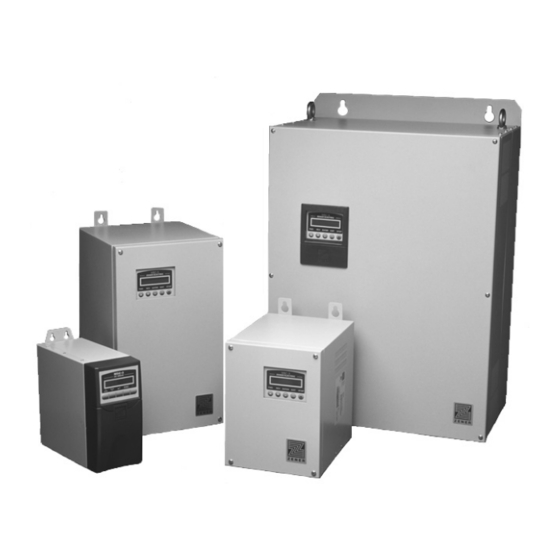
- Page 4 A Zener Drive for Every Application The ZENER MSC-3 series Variable Speed Drive is suitable for all types of loads, producing greater motor torque over the full speed range with ZENER’s unique ‘Flux Plus’ control algorithm. Variable Torque Loads Constant Torque Loads...
- Page 5 MSC-3 Instruction Manual Zener MSC–3 Options SUPPLY VOLTAGE The ZENER MSC–3 is available to operate from the following types of power supplies; Supply Voltage Supply Phase Tolerance Model 380 to 480Vac 3 Phase -15, , +10% MSC–3R 208 to 240Vac...
- Page 6 IM00120 IM00120...
-
Page 7: Table Of Contents
Basic power wiring diagram Supply circuit protection and switchgear Cable sizes Electrical Isolation Fuse Circuit Breaker Ratings for All MSC-3 Models Motor thermal protection MSC-3 Power wiring for Single Phase Supply MSC-3 with a DC Supply Installation practices for Electromagnetic Compatibility (EMC) compliance... - Page 8 Contents Menus Major Features Motor Speed Ramp Dual Ramps Essential Services Override Minimum Speed Idle Function Line Contactor Start Control Reference Selector User References Analogue Inputs and Spanning Extended Feature Option Cards Extended Feature Analogue Output P.I.D. Controller PID Setup Checklist and Tuning PID Application Examples Application: Stair pressurisation fan with internal PID Application: Cooling tower fan with reverse acting internal PID...
- Page 9 MSC-3 Instruction Manual Essential services operation (ESO) Local / remote mode selection MODBUS Quick Set-up Guide MODBUS Status Indicators A00 DEFAULTS Menu A01 Menu Lock Menu Lock Code Entry A02 Def. Display Meter Display A03 Run Display A030 Run Display Format...
- Page 10 Contents D020 I2t D021 I2t zero Hz D022 I2t CNR Hz D03 REVERSE D04 DC INPUT D05 1 Phase Inpt D06 SKIP SPEED D060 SKIP SPEED D061 SKIP RANGE E00 STOP/START Menu E01 COAST STOP E02 DYNAMIC BRK E03 AUTO RESTART E030 ARs ALLOWED E031 AR CLR TIME E04 Reset by PF...
- Page 11 MSC-3 Instruction Manual I08 ESO I09 JOG FWD I10 JOGREV I11 REMOTE I12 EXTERN ALARM I13 EXTERN WARN I14 T1 Input I15 T2 Input I16 Selector 1, I17 Selector 2 and I18 Selector 3 G02 AI(10,11) Config. G020 Input Type...
- Page 12 Contents G10 AI(32,34) & G14 AI(52,54) G100 Input Type & G140 Input Type G101 MIN Input & G141 MIN Input G102 MAX Input & G142 MAX Input G103 Ref @MIN in & G143 Ref @ MIN in G104 Ref @MAX in & G144 Ref @ MAX in G105 Hi Compare Level &...
- Page 13 Accumulators Binary Values Appendix B: MODBUS Protocol - Application Layer Description Memory Model Function Codes Exceptions Display Messages MSC-3 Specifications MSC-3 Output Current Specifications MSC-3 Trouble Shooting Guide Your MSC-3 Setup Notes MSC-3 transportation sizes and weights Glossary IM00120 IM00120...
- Page 15 Requirements for the purchaser’s final product may be substantially different to the requirements for stand-alone inverters. The MSC-3 is intended for use only in fixed wiring applications. It is not intended for use on a flexible supply cable.
- Page 16 Access the inside of the controller and visually check for any damage. Do not attempt to operate the MSC-3 if any obvious damage exists. After the initial inspection, the MSC-3 can be repacked and stored in a clean, dry location until it is required for use.
-
Page 17: Installation
• DC Bus choke is mandatory with MSC-3Jxx (600VAC) and some other models. • The optional DC Bus choke is fitted inside the MSC-3 in all models except Chassis A, IP30. For these models, the DC Bus choke is located in an additional enclosure fitted to the rear face of the MSC-3. -
Page 18: Msc-3 Mechanical Installation Information
Installation MSC-3 Mechanical Installation Information Bolt Diameter Bolt Diameter Chassis A IP30 / NEMA 1 (3 - 11 Amps) Bolt Diameter Bolt Diameter Chassis A IP66 / NEMA 4 (3-11Amps) CAUTION Allow 50mm above, below and either side of the enclosure for ventilation... - Page 19 MSC-3 Instruction Manual Bolt Diameter Bolt Diameter Chassis B (15 - 40 Amps) CAUTION Allow 75mm above, below and either side of the enclosure for ventilation Model Enclosure type Dimensions - tolerance +/- 1.0mm Weight Weight without with choke choke...
- Page 20 CAUTION Allow 100mm above, below and either side of the enclosure for ventilation Model Enclosure type Dimensions - tolerance +/- 1.0mm Weight Weight without with choke choke MSC-3*55 Chassis C 715mm 470mm 290mm 625mm 330mm 677mm 12mm 42Kg 62Kg All types 28.1”...
- Page 21 MSC-3 Instruction Manual HOLE DIAMETER HOLE DIAMETER CAUTION Allow 150mm above, below and either side of the enclosure for ventilation Model Enclosure type Dimensions - tolerance +/- 1.0mm Weight with choke MSC-3R220 220Kg 484lbs MSC-3R260 230Kg 506lb MSC-3R315 240Kg 528lbs...
- Page 22 Installation HOLE DIAMETER HOLE DIAMETER CAUTION Allow 150mm above, below and either side of the enclosure for ventilation Model Enclosure Dimensions - tolerance +/- 1.0mm Weight with type choke and stand MSC-3R220 255Kg 561lbs MSC-3R260 265Kg 583lbs MSC-3R315 275Kg 605lbs as per Chassis D 618mm...
-
Page 23: Msc-3 Power Wiring For 3 Phase Supply
Fuses or circuit breakers of the current limiting type are preferred in order to minimise the total energy let through in the unlikely, but possible, event of a major arcing fault in wiring or within MSC-3 enclosure. Installations that are required to be UL compliant must use UL listed fuses of the amp rating and class detailed on page 10 of this manual. -
Page 24: Fuse Circuit Breaker Ratings For All Msc-3 Models
Motor thermal protection The MSC-3 provides an electronic type thermal overload function that relies on the measured motor current to estimate the thermal conditions of the motor. For complete motor thermal protection, microtherms or thermistors should be installed in the motor winding and wired to the appropriate trip relay. -
Page 25: Msc-3 Power Wiring For Single Phase Supply
Any model MSC-3 can be operated from a single phase AC supply. In addition to the electrical installation information on pages 9 and 10, the following additional constraints apply to operation on a single phase power supply: • The single-phase supply voltage must be within the 3 phase supply voltage limits for the MSC-3... -
Page 26: Msc-3 With A Dc Supply
MSC-3 with a DC Supply Some models of MSC-3 may be used with a DC supply. There are a number of issues to be considered in properly applying MSC-3 in this situation, some of which involve the characteristics of the particular DC supply to be used. -
Page 27: Installation Practices For Electromagnetic Compatibility (Emc) Compliance
In order to achieve the required electrical performance at high frequencies, it is essential that the screen of the cable have a 360º connection to both the MSC-3 gland plate and the motor terminal box. The correct type of metal cable gland to suit the screened cable should be used. The protective earth (PE) conductor should be terminated in the usual way to meet the local wiring codes at the ground terminals provided in the MSC-3 and the motor. - Page 28 Installation Control cable gland. No special EMC requirement. Plastic or other cable gland may be used. REV ENTER EXIT STOP See gland plate detail on left for control cable exit location Gland Plate Detail Viewed from Below CAUTION Remove gland plate before drilling holes AC supply screened cable...
- Page 29 MSC-3 Instruction Manual ENTER EXIT STOP CAUTION Remove gland plate before drilling holes No special EMC AC supply requirement here. Plastic screened cable or other cable gland may not required be used Screened control cable Metal cable gland with Screened 360°...
- Page 30 Installation ENTER EXIT STOP CAUTION Remove gland plate before drilling holes L1 L2 L3 M1 M2 M3 No special EMC requirement here. Plastic or other cable gland may be used Metal cable gland with 360° screen termination Screened control cable Screened power cable AC supply...
- Page 31 MSC-3 Instruction Manual ENTER EXIT STOP CAUTION Remove gland plate before BRAKING RESISTOR O P T I O N A L drilling holes L1 L2 L3 M1 M2 M3 No special requirement Metal cable gland here. with 360° screen termination...
- Page 32 Installation MSC-3 ZENER ELECTRIC ENTER EXIT STOP CAUTION Remove gland plate before drilling holes No special EMC requirement here. Metal cable gland with 360° screen Screened termination control cable Screened power cable AC supply screened cable not required Metal cable gland with Motor isolation 360°...
-
Page 33: Control Connections And Configuration
Assignment of particular control functions to terminals (inputs) and relays (status outputs). These can be selected individually. The MSC-3 control terminals can be configured, on an individual terminal basis, to suit a wide variety of applications. This provides enormous flexibility. -
Page 34: Industrial Terminals Typical Connection Diagram - Terminal Config 1
This section shows the typical configurations applicable to a wide range of industrial applications. The motor speed may be controlled from the local console on the MSC-3 or a remote signal source. Switching between local and remote operation is controlled by a contact closure. This terminal configuration is the factory default. -
Page 35: Quick Setup For Terminal Config 1
See Remote Override Operation on +5V D1 page 102. In “local” the MSC-3 is stopped and started from the front panel console. In “remote”, the MSC-3 stop / start is controlled from the terminal strip. Local... - Page 36 Control connections and configuration STEP 3. Choose your speed reference and connect it as shown. Speed control from an external potentiometer MSC - 3 Control Board This is typically used for simple manual speed control. See also Console Reference below. SCN Vref 1k to 10k ohm potentiometer...
- Page 37 MSC-3 Instruction Manual STEP 4. Follow the instructions on page 47 for MSC-3 start up, setting the parameters according to the table below. Alternative values may be used to suit the application. Page for detailed Menu Menu Item Suggested Setting...
- Page 38 This setup is for a typical centrifical pump application that requires water pressure control using a water pressure transducer and PID controller function provided by the MSC-3. Prior to commissioning, you will need to know the type of water pressure transducer signal that is to be used (0-10V,4-20mA etc).
- Page 39 MSC-3 Instruction Manual STEP 4 Follow the instructions on page 47 for MSC-3 startup, setting the parameters according to the table below. Alternate values may be used to suit the application. See the H00 PID Control beginning on page 113 for additional information on PID configuration and tuning.
- Page 40 Connect your control wiring as shown. CAUTION Do not connect the wire to terminal 6 yet. The terminal configuration should not be changed while the MSC-3 is enabled. The function of terminals D1...4 are programmable. In this configuration (Terminal config...
- Page 41 MSC-3 Instruction Manual STEP 3 Choose your speed reference and connect it as shown Speed control from an external potentiometer MSC - 3 Control Board This is typically used for simple manual speed control. See also Console Reference below. SCN Vref...
- Page 42 Control connections and configuration STEP 4 Follow the instructions on page 47 for MSC-3 startup, setting the parameters according to the table below. Alternate values may be used to suit the application. Page for detailed Menu Menu Item Suggested Setting...
- Page 43 Connect your control wiring as shown. CAUTION Do not connect the wire to terminal 6 yet. The terminal configuration should not be changed while the MSC-3 is enabled. The function of terminals D1...4 are programmable. In this configuration the following...
- Page 44 Control connections and configuration STEP 3 Choose your speed reference and connect it as shown Speed control from an external potentiometer MSC - 3 Control Board This is typically used for simple manual speed control. See also Console Reference below. SCN Vref 1k to 10k ohm potentiometer...
- Page 45 MSC-3 Instruction Manual STEP 4 Follow the instructions on page 47 for MSC-3 startup, setting the parameters according to the table below. Alternate values may be used to suit the application. Page for detailed Menu Menu Item Suggested Setting information...
-
Page 46: Hvac Terminals Typical Connection Diagram – Terminal Config 3
Input reference source Single direction 2 wire control with ESO Optional Wiring Local / Remote If selection between In “local” the MSC-3 local and remote is is controlled from not required, place a the front panel Essential Services link between terminals console. - Page 47 CAUTION Do not connect the wire to terminal 6 yet. The terminal configuration should not be changed while the MSC-3 is enabled. Essential Services Override (ESO). See page 51 for detailed information Local / Remote Selection The Local/Remote Selection can be used in conjunction with any of the above circuits.
- Page 48 Quick Setup for Config 3. STEP 3. Choose your speed reference and connect it as shown. Speed control from an external potentiometer MSC - 3 Control Board This is typically used for simple manual speed control. See also Console Reference below. SCN Vref 1k to 10k ohm potentiometer...
- Page 49 MSC-3 Instruction Manual STEP 4. Follow the instructions on page 47 for MSC-3 start up, setting the parameters according to the table below. Alternative values may be used to suit the application. Page for detailed Menu Menu Item Suggested Setting...
-
Page 50: Application: Supply Air Or Smoke Spill Fan
Input reference source See page 51 for detailed information STEP 3 Follow the instructions on page 47 for MSC-3 startup, setting the parameters according to the table below. Alternate values may be used to suit the application. Page for detailed Menu... -
Page 51: Application: Return Air Fan
MSC-3 is enabled. Input reference source STEP 3 Follow the instructions on page 47 for MSC-3 startup, setting the parameters according to the table below. Alternate values may be used to suit the application. Page for detailed Menu... -
Page 52: Application: Stair Pressurisation Fan With Internal Pid
PID controller function provided by the MSC-3 extended features option. The MSC-3 is configured to run in essential services override (ESO) mode. Prior to commissioning, you will need to know the type of air pressure transducer signal that is to be used (0-10V,4-20mA etc). - Page 53 MSC-3 Instruction Manual STEP 4 Follow the instructions on page 47 for MSC-3 startup, setting the parameters according to the table below. Alternate values may be used to suit the application. Page for detailed Menu Menu Item Suggested Setting information...
-
Page 54: Application: Stair Pressurisation Fan With External Pid
This setup is for a typical HVAC stair pressurisation fan application that requires air pressure control using an air pressure transducer and a PID controller external to the MSC-3. The MSC-3 is configured to run in essential services override (ESO) mode. Prior to commissioning, you will need to know the type of speed signal that is to be used (0-10V, 4-20mA etc) between the output of the external PID controller and the MSC-3. -
Page 55: Application: Cooling Tower Fan With Reverse Acting Internal Pid
This setup is for a typical cooling tower fan application that requires water temperature control using a water temperature transducer and the PID controller function provided by the MSC-3 extended features option board. Prior to commissioning, you will need to know the type of temperature sensor signal that is to be used (0-10V, 4-20mA etc). - Page 56 Quick Setup for Config 3. STEP 4 Follow the instructions on page 47 for MSC-3 startup, setting the parameters according to the table below. Alternate values may be used to suit the application. Page for detailed Menu Menu Item Suggested Setting...
-
Page 57: Eia/Rs-485 Communications Wiring
Values of 100 or 120 Ohms are commonly used, connected between the A and B terminals of the first and last devices on the cable run. For convenience, the MSC-3 EIA/RS-485 interface incorporates a 120 Ohm terminating resistor that is controlled by menu item G167 TERMINATOR. - Page 58 • The EIA/RS-485 standard allows a total of 32 standard load units on a network segment. Each MSC-3 interface is 0.5 standard load units, allowing a master device and at least 62 MSC-3 drives. Network loading for other equipment may vary – check with the equipment manufacturer.
-
Page 59: Extended Features Option Wiring
MSC-3 Instruction Manual Extended Features Option Wiring IM00120 IM00120... -
Page 61: Msc-3 Start Up
The MSC-3 is supplied with a link between the EN terminal and the +5V terminal which is all that is required to run the MSC-3 from the console. A connection between these two terminals must always be made for the motor to run. -
Page 62: Run Display
▼ REV button to decrease it. The motor will accelerate or decelerate to the desired speed. If the motor shaft rotates in the wrong direction remove the input power, wait for the MSC-3 to discharge and swap any two motor phase wires. Re-apply input power and select a direction by pressing ▲ FWD or ▼... -
Page 63: Meter Display
MSC-3 Instruction Manual Meter Display (Meter Display facet) The Meter Display shows other MSC-3 operating values such as 25.0Hz 0.1kW output current, output power, motor ENTER 8.0A load as well as motor speed. The PID facet displays the process variable and set point value. -
Page 64: Major Features
MSC-3 Start Up Major Features Motor Speed Ramp The MSC-3 has a programmable Ramp with adjustable acceleration, deceleration and S-curve rates. Individual settings are provided for the linear and curved portions of the ramp Frequency Acceleration Rate Adjusting the linear... -
Page 65: Dual Ramps
In addition, the Auto Restart function is automatically enabled with unlimited auto restarts permitted. In order to allow the MSC-3 to be independently optimised for both the usual operating condition and operation in ESO mode, separate parameters are provided for ESO and non ESO operating modes. -
Page 66: Minimum Speed Idle Function
• I08 ESO (input terminal selection) Minimum Speed Idle Function The minimum speed idle function will stop operation if the MSC-3 output frequency has been operating with output frequency equal to C010 MIN Hz for a specified time interval. The time interval is specified by C011 IDLE DELAY. -
Page 67: Line Contactor Start Control
The MSC-3 can be optionally configured so that it is powered by a customer supplied external 24V DC supply independent of the mains power supply. In this mode the MSC-3 is capable of controlling an external line contactor to apply mains power to its own power circuits. The MSC-3 remains operational if either or both 24V DC or mains power is present. - Page 68 To avoid MSC-3 relay contact damage, please ensure the contactor coil ratings do not exceed 2A @ 250Vac. With 24Vdc applied, the MSC-3 remains idle until it receives a forward or reverse command. The AUX_ PWR relay function will then operate the input line contactor charging the MSC-3. When charging is complete the motor is run as required.
-
Page 69: Reference Selector
MSC-3 Instruction Manual Reference Selector The reference selector is a multiplexor function that uses three digital inputs to select 1 of 8 reference sources. The High/Low states of the three digital inputs I16 Selector 1, I17 Selector 2 and I18 Selector 3 make 8 unique combinations. Each combination is assigned a reference source as given... -
Page 70: Analogue Inputs And Spanning
MSC-3 Start Up Analogue Inputs and Spanning The MSC-3 analogue inputs have been designed with the following features: • Configurable voltage (V) or current (mA) input configuration. • Easy to configure spanning and translation. • High and Low compare logic outputs with adjustable thresholds • The diagram below illustrates the design:... -
Page 71: Extended Feature Option Cards
Extended Feature Option Cards The MSC-3 may be fitted with 1 or 2 extended features cards. Each card provides additional analogue and digital inputs and outputs. The cards may be fitted in either the left or right option card sockets. -
Page 72: P.i.d. Controller
Input Application examples: • Stair Pressurisation Control: An air pressure transducer and the PID controller of the MSC-3 are configured to run in essential services override (ESO) mode. • Cooling Tower Fan Control: A water temperature transducer and the PID controller of the MSC-3 are configured to run typically in remote mode. -
Page 73: Pid Setup Checklist And Tuning
MSC-3 Instruction Manual PID features include: • Three term tuning (PB%, Ti, and Td). • Output saturation with integrator anti-windup. • Reference and feedback signal source selections. • Open loop to closed loop initialisation. • Process variable spanning and offset available through the selected analogue input. - Page 74 MSC-3 Start Up 2.2. Specifically check the desired maximum motor frequency at which the process may be safely driven. Refer to C02 MAX Hz to check the maximum Hz setting. 2.3. Configure the analogue input that you intend to use for the PV signal (feedback transducer), so that it is the correct type (Volts, mA) and signal range (0-10V, 4-20mA etc).
-
Page 75: Pid Application Examples
PID controller function provided by the MSC-3. Prior to commissioning, you will need to know the type of air pressure transducer signal that is to be used (0-10V, 4-20mA). -
Page 76: Communications
• Read Property • Write Property Data Link Layer The MSC-3 implements the BACnet MS/TP Data Link Layer as a master device. The communication port is EIA/RS-485 compliant and is isolated from ground and other circuits. MAC ID / Device Object Instance Set via the front panel. -
Page 77: Bacnet Set-Up And Operation
Control of the run function (ie starting and stopping) is from the console. BACnet commands do not influence the starting and stopping of the MSC-3 in local mode. The speed reference used for local operation is determined by the reference source selected by parameter F02 LOCAL REF. See list of speed references for available choices. -
Page 78: Bacnet Status Indicators
Setting this parameter to ENABLED will terminate the line. • G169 Serial No.: Each BACnet device has a name, which is required to be unique. To ensure that there are no duplicated names, the MSC-3 serial number is used as part of the device object name. -
Page 79: Essential Services Operation (Eso)
Control of the run function (ie starting and stopping) is from the console. MODBUS commands do not influence the starting and stopping of the MSC-3 in local mode. The speed reference used for local operation is determined by the reference source selected by parameter F02 LOCAL REF. See list of speed references for available choices. -
Page 80: Modbus Status Indicators
• G168 Comms Lost Time: Check the time interval is greater than the system scan interval. • G169 Serial No.: Each MODBUS device has a name, which is required to be unique. To ensure that there are no duplicated names, the MSC-3 serial number is used as part of the device object name. -
Page 81: A02 Def. Display
The selected display will show when the MSC3 is powered on or when a menu is on show and left unattended for 2 minutes. Meter Display (Meter Display facet) The Meter Display shows other MSC-3 operating values such as 25.0Hz 0.1kW output current, output power, motor ENTER 8.0A... -
Page 82: A030 Run Display Format
MSC-3 Start Up A030 Run Display Format A030 Run Display Format > 999.9 Available Choices: > 9999 > 999.9 > 99.99 > 9.999 • Press once to begin. • Use the ▲ / ▼ buttons to choose a display format. -
Page 83: Load Factory Defaults
• Press ESC to continue with the existing set of parameters Load Custom Defaults? Typically when the MSC-3 is first commissioned for operation parametric changes are made to suit the application. Once the desired operational configuration is settled, it is recommended that all parameters are stored to Custom defaults. -
Page 84: Save Custom Defaults
• Press ESC to continue with the existing set of parameters Save Custom Defaults? It is recommended to save newly configured parameters after an MSC-3 is first set up for an application. Called “Custom Defaults”, new and existing parameters form a known configuration that serve as a reference for future changes to the MSC-3 and its application. -
Page 85: B01 Motor Volts
• Press ESC to abandon the value change. The value entered is taken from the motor nameplate and is an important parameter of the motor control algorithm. In general the adjustment range is 22.5%...171% of MSC-3 rated current. However the actual range of values is model dependant. -
Page 86: C00 Performance Menu
• Press ESC to abandon the value change. This sets the minimum frequency that the MSC-3 will run at when given a run signal. The value is entered in Hz. There must be a difference of at least 5Hz between the C010 MIN Hz and the C02 MAX Hz setting. -
Page 87: C011 Idle Delay
• Press to accept the new value OR • Press ESC to abandon the value change. The C011 IDLE DELAY sets the time interval of operation at minimum speed before the MSC-3 enters the idle state. Refer to “Minimum Speed Idle Function” for details. -
Page 88: C03 Ramp
The C031 DECEL TIME is the time taken for the motor to go from motor rated speed down to zero speed (assuming minimum C032 S TIME). An MSC-3 with B03 MOTOR Hz set to 50 Hz and C031 DECEL TIME set to 10.0 seconds will take 10 seconds to go from 50 Hz to 0 Hz. -
Page 89: C033 Dual Ramp
(assuming minimum C032 S TIME). A MSC-3 with the B03 MOTOR Hz set to 50 Hz and an C034 ESO RAMP set to 10 seconds will take 10 seconds to go from 0Hz to 50Hz. -
Page 90: C04 Flux Plus
When disabled the flux plus decreases with increasing speed. This allows more efficient operation of the MSC-3 on loads that have a high starting torque but do not require any extra torque during normal operation. If your load requires high torque throughout the entire speed range then enable C041 HiSpd Flux+. -
Page 91: C05 Slip Comp
(synchronous speed) and is dependent on load. Slip Comp can provide compensation for this varying slip to produce constant shaft speed under varying loads. The MSC-3 estimates the slip of the motor using the parameters entered in the MOTOR parameters menu and the motor load. A value of 100% will make the shaft speed equal the synchronous speed. -
Page 92: D01 Current Lim
• Press ESC to abandon the value change. This sets the maximum output current of the MSC-3. If excessive load is applied to the motor, the drive will only apply this amount of current to the motor until the overload condition is removed. Current limiting is achieved by reducing the speed of the motor. -
Page 93: D020 I2T
D020 I2t D020 I2t 40.0 Amps Range: 18...100% of the MSC-3 current rating (model dependant) • Press to edit the value. • Press ▲/ ▼ to make changes to the value. • Press to accept the new value OR • Press ESC to abandon the value change. -
Page 94: D03 Reverse
• Use the ▲ / ▼ buttons to enable or disable DC input operation. • Press to confirm the choice. This feature allows the MSC-3 to operate from a DC Input supply. The DC Supply voltage should be at least 1.414 times higher than the motor voltage. -
Page 95: D060 Skip Speed
MSC-3 Instruction Manual Operating Reference D061 SKIP RANGE MSC-3 ramps through this range D060 SKIP SPEED Desired Speed reference D060 SKIP SPEED D060 SKIP SPEED 30 Hz Range: 0...200Hz • Press to edit the value. • Press ▲/ ▼ to make changes to the value. -
Page 96: E00 Stop/Start Menu
E03 AUTO RESTART Auto Restart allows the MSC-3 to automatically attempt to restart after a trip occurs. If the MSC-3 trips, it will wait 10 seconds then attempt to clear the fault. If it is unsuccessful it will keep trying every ten seconds. -
Page 97: E030 Ars Allowed
• Press ESC to abandon the value change. If the MSC-3 operates for the E031 A/R CLR TIME without any trips, the number of restarts is reset to the value of E030 A/Rs ALLOWED. Set the E031 A/R CLR TIME to 6 secs for infinite auto restarts... -
Page 98: E05 Motor Resync
• Use the ▲ / ▼ buttons to enable or disable reset by power fail operation. • Press to confirm the choice. When enabled, the MSC-3 will scan for the motor shaft speed. When detected, a smooth transition into operation begins. The motor resynchronisation function avoids current limit braking. -
Page 99: F01 Remote
• Use the ▲ / ▼ buttons to select a reference. • Press to confirm the choice. When the drive is operating in remote mode the MSC-3 will take its speed reference from the selected reference source. F02 LOCAL F02 LOCAL REF >... -
Page 100: F03 Eso
• Use the ▲ / ▼ buttons to select a reference. • Press to confirm the choice. When the drive is operating in ESO mode the MSC-3 will take its speed reference from the selected reference source. F04 JOGFWD F04 JOGFWD REF >... -
Page 101: F08 Console Cfg
Power-On Reset mode sets the console reference to zero when the MSC-3 is powered on. This mode is active if neither stop reset nor persistent mode is active. Stop Reset mode sets the console reference to zero whenever the MSC-3 is powered on or when commanded to stop running the motor. -
Page 102: F09 Comms Preset
Comms Lost Time to zero disables the detection of communications loss. F10 PRESETS There are 8 preset references for the MSC-3. Most are used in conjunction with the Reference Selector. Each preset is expressed as a percentage of C03 MAX Hz. -
Page 103: G00 Input/Output Menu
MSC-3 Instruction Manual G00 INPUT/OUTPUT Menu Easily the menu containing the most configuration parameters, the G00 INPUT/OUTPUT menu is where all terminal strip configurations are found. G01 Inpt fxn CFG This menu provides a way to map a finite set of physical digital inputs to an internal set of input functions. -
Page 104: Duplicate Selections
MSC-3 Start Up Duplicate Selections It is possible to select the same input terminal for several input functions. In some cases a single digital input feeding several input functions may not be desirable. When an input terminal is selected for the 2nd (or 3rd, 4th,…) time, the MSC3 presents a warning message and question asking to remove all... -
Page 105: I00 Fwd & Latch
MSC-3 Instruction Manual I00 FWD & LATCH I00 FWD & LATCH > D3(4) See the list of the G01 Inpt fxn CFG menu Available Choices: • Press once to begin input selection. • Use the ▲ / ▼ buttons to select a digital signal source. -
Page 106: I04 Rev
MSC-3 Start Up While this input is held the motor will run in the forward direction. When the input is removed the motor will stop running (non-latching). The I03 FWD function disregards the state of the I02 ~STOP input and the drive will not stop while I03 FWD input is present and the Enable input is wired to +5V. -
Page 107: I08 Eso
• Use the ▲ / ▼ buttons to select a digital signal source. • Press to confirm the choice. ESC to abandon the change. While this input is held the MSC-3 will operate in Essential Services Override (ESO). Refer to the ESO feature description on page 51 for details. -
Page 108: I12 Extern Alarm
Remote speed reference. When the contact is opened the MSC-3 will be controlled from the console and will run at the speed set by the Local speed reference. This input requires other terminals to stop and start the motor. -
Page 109: I16 Selector 1, I17 Selector 2 And I18 Selector 3
G02 AI(10,11) Config. The MSC-3 is equipped with a single analogue input as standard and can be configured to receive either: 0 to 5V, 0 to 10V or 0 to 20mA. Additionally the input has a customisable span as well as a high and low compare thresholds. -
Page 110: G022 Max Input
MSC-3 Start Up If the G020 AN IN mode is configured for > Volts then G021 MIN input will be displayed with units of volts (V) otherwise G021 MIN input will be displayed with units of milliamps (mA). In either case the minimum input for spanning is determined by this parameter. -
Page 111: G025 Hi Compare Level
MSC-3 Instruction Manual • Press ESC to abandon the value change. Regardless of how the analogue input is configured the maximum reference for input spanning is determined by this parameter. The G024 Ref @MAX in parameter corresponds to the G022 MAX input to define the input spanning configuration. -
Page 112: G03 Rl1
G03 RL1(15,16) As standard the MSC-3 is equipped with 2 relays each with a single normally open contact. This menu allows configuration of Relay #1 (RL1 on the terminal strip). Configuration parameters include: a relay signal function selection, relay signal inversion option and delay on and off interval specifications. -
Page 113: G031 Rl1 Sense
MSC-3 Instruction Manual • Press once to begin input selection. • Use the ▲ / ▼ buttons to select the output function for relay #1 operation. • Press to confirm the choice. ESC to abandon the change. G031 RL1 Sense G031 RL1 Sense >... -
Page 114: G04 Rl2
This parameter sets the relay off delay for relay #1 G04 RL2(17,18) As standard the MSC-3 is equipped with 2 relays each with a single normally open contact. This menu allows configuration of Relay #2 (RL2 on the terminal strip). Configuration parameters include: a relay signal function selection, relay signal inversion option and delay on and off interval specifications. -
Page 115: G043 Rl2 Toff
MSC-3 Instruction Manual • Press ESC to abandon the value change. In some instances it is desirable to delay the activation of a relay to assist with signal interlock for example. This parameter sets the relay on delay for relay #2... -
Page 116: G052 %L Warning
The output of the %load warning feature is available as a relay function. The procedure for calibration is: 1. Run the MSC-3 at half of full speed 2. Find the G052 %L WARNING menu, press and select > Low Speed CAL 3. -
Page 117: G07 Timer Config
MSC-3 Instruction Manual When G06 REMOTE OVRD is enabled, the push button on the console can toggle between LOCAL and REMOTE mode of operation. Refer to the I11 REMOTE feature for details of LOCAL and REMOTE operation. G07 TIMER CONFIG Timer parameters such as timer intervals and timer type are configured within this menu. -
Page 118: G080 Do Signal & G120 Do Signal
MSC-3 Start Up An extra digital output is available when the MSC-3 is fitted with an extended features option. Configuration parameters maintained by the subsequent menus include: signal function selection, signal inversion option and delay on and off interval specifications. Either one or two extended features options may be fitted. -
Page 119: G09 Th(40,42) & G13 Th(60,62)
G10 AI(32,34) & G14 AI(52,54) An extra analogue input is available when the MSC-3 is fitted with an extended features option. This extra analogue input can be configured to receive either: 0 to 5V, 0 to 10V or 0 to 20mA. Additionally the input has a customisable span as well as a high and low compare thresholds. -
Page 120: G102 Max Input & G142 Max Input
MSC-3 Start Up • Press to accept the new value OR • Press ESC to abandon the value change. If the G100 Input Type is configured for > Volts then G101 MIN input will be displayed with units of volts (V) otherwise G101 MIN input will be displayed with units of milliamps (mA). -
Page 121: G105 Hi Compare Level & G145 Hi Compare Level
G11 AO(36,38) & G15 AO(56,58) An analogue output is available when the MSC-3 is fitted with an extended features option. This extra analogue output can be configured for either: 0 to 5V, 0 to 10V or 0 to 20mA output. Additionally the output has customisable parameters for translation and scaling. -
Page 122: G111 Ao Source & G151 Ao Source
The analogue output is configurable for voltage or milliamp output. This selection will configure the output circuitry for either voltage input or current (mA) output without any need to access MSC-3 hardware. See the Extended Feature Analogue Output feature for details. -
Page 123: G114 Min Output & G154 Min Output
See the Analogue Output feature for details. G16 EIA/RS-485 The MSC-3 has as standard EIA/RS-485 communications with the following features: Choice of protocol: BACNET / MODBUS. Selectable data rates. Selectable parity checking. -
Page 124: G161 Bits/Sec
MSC-3 Start Up G160 Protocol > none Available choices: none MODBUS BACnet • Press once to begin input selection. • Use the ▲ / ▼ buttons to select the communications protocol. • Press to confirm the choice. ESC to abandon the change. -
Page 125: G163 Mac/Dev Id
Each device on an EIA/RS-485 network requires a unique Media Access Control Identification address code (MAC ID). The MAC ID is used to identify the MSC-3 on the communication network. It is necessary change this value from the factory default when the MSC-3 is first set up. -
Page 126: G166 Run Signals
For MODBUS, any data packet addressed to the MSC-3 and free of transmission errors will reset the timer and the timing interval will begin again. For BACnet, a token pass addressed to the MSC-3 and free of transmission errors will reset the timer and the timing interval will begin again. -
Page 127: H00 Pid Control
MSC-3 Instruction Manual H00 PID Control This menu is the entry point for the PID controller menus where adjustments can be made. Parameters that may be viewed or adjusted are: the Proportion Band, the integrator gain, the differential gain, the output clamp limit values, the process and set point variable choices and PID scale and units for the PID display. -
Page 128: H03 Td (Sec)
MSC-3 Start Up H03 Td (sec) H03 Td (sec) > 0.0 sec/r Range: 0.0...5.0 sec/r • Press to edit the value. • Press ▲/ ▼ to make changes to the value. • Press to accept the new value OR • Press ESC to abandon the value change. -
Page 129: H07 Pv Choice
MSC-3 Instruction Manual H07 PV choice H07 PV choice >AN IN Available Choices: > AN IN > LHS AN IN (if left-hand Extended Features card fitted) > RHS AN IN (if right-hand Extended Features card fitted) • Press once to begin a selection. -
Page 130: S00 Service
MSC-3 Start Up S00 SERVICE The S00 SERVICE menu is a collection of displays and menus specifically for service and service personnel and so summarised description of each display and menu follows Version display Ver 5.0.0h This display reveals the software version in operation without having to restart the drive. -
Page 131: Temperature Sensor Display
MSC-3 Instruction Manual The MSC-3 internal cooling fans will be forced ON while ever the S04 FAN OVERRIDE parameter is set to ENABLED. When DISABLED, the fans will operate according to internal temperature measurements. Temperature sensor display The temperature sensor menu contains a set of displays that show the reading of each sensor within the MSC3 chassis. -
Page 132: Extended Features Digital Input Display
MSC-3 Start Up Extended Features Digital Input Display Refer to the “Extended Features Cards” section for setup information. When one or more extended features cards are fitted extra displays, values and choices appear throughout the menu system. Like the standard digital and analogue I/O, the state of the I/O found on the Extended Feature cards are viewable. -
Page 133: M02 Date - Time
M02 Date – Time M02 Date - Time 2013-11-28 14:41 This display reveals the date and time of MSC-3 time keeping. The format for the date and time is: “20yy-mm-dd hh:mm”. kWhr & Hours Run This is a menu for pass code access to additional menus that manage the kWhrs and Hours Run accumulating meters kWhr &... -
Page 134: System Settings
MSC-3 Start Up System Settings The menu contained within are intended for service personnel only and so are pass code protected. Please contact your local service agent for further details. Appendix A: BACnet Protocol – Application Layer Description Objects and Properties Supported... -
Page 135: Analog Values
MSC-3 Instruction Manual Analog Values Instance ID Object Name Description Units Present Value Access Cpreset Speed reference Preset Preset analog value for general use Accel time Acceleration time 0 - max speed seconds Decel time Deceleration time max speed - 0... -
Page 136: Binary Values
MSC-3 Start Up Binary Values Instance ID Object Name Description Active Text Inactive Text Present Value Access Run fwd Run FWD Command Active Inactive Run rev Run REV Command Active Inactive Reset Reset Command RESETTING Inactive ESO Mode ESO ACTIVE... -
Page 137: Appendix B: Modbus Protocol - Application Layer Description
Power hardware over temperature trip detected I2tTrip Over current trip detected Tripped one or more trips detected Voltage Limit MSC-3 operating at or near max DC bus voltage Current Limit MSC-3 operating at or near max output current At-Zero-Speed Motor is at zero speed... - Page 138 10 (1) Power Output power ÷ 10 11 (1) ACvolts AC line voltage ÷ 10 12 (1) Temperature MSC-3 power hardware temperature 13 (1) I2tused Thermal capacity 14 (1) PID ref PID reference ÷ 10 15 (1) PID feedback PID feedback ÷...
-
Page 139: Function Codes
• Function code 43: Read device Identification, Sub Code 14 The function codes supported are explained in detail in the document entitled “MODBUS Application Protocol Specification V1.1b”. Available from http://www.modbus.org. Implementation options and constraints of the MSC-3 are explained in the following sections. IM00120 IM00120... - Page 140 Response: Function code 1 byte Byte count 1 byte 1 to 3 Coil status 1 to 3 bytes MSC-3 discrete input states Error: Function code 1 byte 130 (128+function code, 0x82) Exception code 1 byte 1, 2 or 3 Function Code 03: Read Holding Registers...
- Page 141 Function Code 06: Write Single Register Request: Function code 1 byte Register address 2 bytes 0 to 9 Register value 2 bytes Data for MSC-3 holding register Response: Function code 1 byte Register address 2 bytes 0 to 9 Register value 2 bytes...
- Page 142 0, 17 Return slave busy count 0, 18 Return network character overrun count 0, 20 Clear overrun counter and flag Data 2 bytes Data for MSC-3 MODBUS diagnostics Response: Function code 1 byte Sub function 2 bytes 0,2,10...18,20...
- Page 143 MSC-3 Instruction Manual Request: Function code 1 byte Starting address 2 bytes 0 to 4 Quantity of outputs 2 bytes 1 to 5 Byte count 1 byte Output value 1 byte Response: Function code 1 byte Starting address 2 bytes...
-
Page 144: Exceptions
Exception code 1 byte 1, 2 or 3 Exceptions The exception codes supported are explained in detail in the document entitled “MODBUS Application Protocol Specification V1.1b”. Exception codes supported by the MSC-3 are: Exception Name code ILLEGAL FUNCTION CODE ILLEGAL DATA ADDRESS... -
Page 145: Display Messages
MSC-3 Instruction Manual Display Messages The MSC-3 displays a variety of messages on the second line of its display to indicate the drive status. These messages may be divided into two types, trip messages and run messages. The MSC-3 will protect itself a variety of fault conditions. When one of these conditions is experienced the MSC-3 will trip, shut down the motor and display one of the following messages. - Page 146 MSC-3 Start Up EN REM The MSC-3 has an enable signal but no direction selected in remote mode IDLE LOC The MSC-3 is idle in local mode FWD LOC The MSC-3 is running in the FWD direction in local mode...
-
Page 147: Msc-3 Specifications
MSC-3 Instruction Manual MSC-3 Specifications Differential Input Input Supply Voltage 0 to 5V range MSC-3R 380 to 480Vac, 3Ø 0 to 10V range MSC-3J 440 to 600Vac, 3Ø 0 to 20mA range MSC-3L 208 to 240Vac, 3Ø 4 to 20mA range... - Page 148 MSC-3 Start Up Model Max. Supply Short Max. Fuse Max. Wire Size Max. Tightening Circuit Rating Fuse Class Torque Size (Amps rms Symmetrical) 240V MSC-3L3 18,000A, 240V 10 A.W.G (6mm 15.6 in.lb (1.76Nm) MSC-3L5 18,000A, 240V 10 A.W.G (6mm 15.6 in.lb (1.76Nm)
-
Page 149: Msc-3 Output Current Specifications
395.0 539.0 * L, R or J for models up to MSC-3 *40. L or R for models MSC-3 *55 and up. These currents apply to all ranges MSC-3 at an ambient temperature of 40ºC (104ºF) independent of the input voltage. MSC-3 may be applied at higher ambient temperatures at reduced ratings. Please consult the factory for ratings for ambients above 40ºC (104ºF). -
Page 150: Msc-3 Trouble Shooting Guide
Check input power wiring, refer to the illuminate. connected properly. MSC-3 Electrical Installation Diagram. Input voltage not within Measure the input voltage at the MSC-3 specification. input terminals. Check with specifications. Motor does not rotate Enable signal is not active. - Page 151 Voltage limit circuit is This is a normal operating mode for the decelerate in the time operating. MSC-3. When the load is being decelerated set by the DECEL ramp too fast, the MSC-3 limits the voltage and V LIMIT message regenerated by the motor by extending the appears.
-
Page 152: Your Msc-3 Setup Notes
MSC-3 Start Up Your MSC-3 Setup Notes Photocopy this page or complete in pencil Date Site Designator MSC-3 Serial No. Parameter User Default Parameter User Default A01 Menu Lock UNLOCKED F07 USER REF 2 CONSOLE A02 Def. Display METER DISPLAY... - Page 153 MSC-3 Instruction Manual Parameter User Default Parameter User Default G042 ON Delay G155 MAX Output G043 OFF Delay G160 Protocol none G050 UNDER SPEED 20.0 G161 bits/sec 19200 G051 OVER SPEED 80.0 G162 Parity Even parity G06 REMOTE OVRD DISABLED...
-
Page 154: Transportation Sizes And Weights
MSC-3 Start Up MSC-3 transportation sizes and weights The table below lists the approximate dimensions and weights for MSC-3 models in the standard packing material. Weight Weight Model Enclosure Type Shipping Dimensions without Packaging with Choke Choke MSC-3*3 Chassis A... -
Page 155: Glossary
MSC-3 Instruction Manual Glossary ~STOP The logical inverse of STOP. This circuit must be closed for the MSC-3 to run. 2-wire control Control of the stop / start function by a simple contact closure (eg a start / run switch contact). - Page 156 AC input current measured in a way that reflects the true heating value of the current. The terminal on the MSC-3 for the connection of the screen of all cabled associated with analog and digital control functions. Underwriters Laboratories Inc. An American organization involved in product safety standards and certification.
- Page 158 ZENER ELECTRIC PTY LIMITED ACN 001 595 428 366 Horsley Rd PO Box 347 Tel: +61 2 97953600 Milperra NSW 2144 Milperra NSW 2144 Fax: +61 2 97953611 Australia Australia Email: zener@zener.net http://www.zener.net © Zener Electric Pty Limited 2014 IM00120 26 October 2014...
Need help?
Do you have a question about the MSC-3 and is the answer not in the manual?
Questions and answers