Mitsubishi MELSEC Q Series User Manual
Cc-link system master/local module
Hide thumbs
Also See for MELSEC Q Series:
- Programming manual (1296 pages) ,
- User manual (814 pages) ,
- Reference manual (532 pages)

Related Manuals for Mitsubishi MELSEC Q Series


Summary of Contents for Mitsubishi MELSEC Q Series
- Page 1 CC-Link System Master/Local Module User's Manual Mitsubishi Programmable Logic Controller QJ61BT11N...
-
Page 3: Safety Precautions
• SAFETY PRECAUTIONS • (Always read these precautions before using this equipment.) Before using this product, please read this manual and the relevant manuals introduced in this manual carefully and pay full attention to safety to handle the product correctly. The precautions given in this manual are concerned with this product. - Page 4 [DESIGN PRECAUTION] DANGER • Do not write data into the "system area" of the buffer memory of intelligent function modules. Also, do not output the "prohibited to use" signal as the output signal to an intelligent function module from the PLC CPU. Writing data into the "system area"...
- Page 5 [WIRING PRECAUTIONS] CAUTION • When turning on the power and operating the module after installing is completed, always attach the terminal cover that comes with the product. There is a risk of malfunction if the terminal cover is not attached. •...
- Page 6 [STARTING AND MAINTENANCE PRECAUTIONS] CAUTION • Do not disassemble or modify each module. Doing so could cause failure, malfunction, injury or fire. • Switch all phases of the external power supply off when mounting or removing the module. Not doing so may cause failure or malfunction of the module. •...
-
Page 7: Revisions
This manual confers no industrial property rights or any rights of any other kind, nor does it confer any patent licenses. Mitsubishi Electric Corporation cannot be held responsible for any problems involving industrial property rights which may occur as a result of using the contents noted in this manual. -
Page 8: Table Of Contents
INTRODUCTION Thank you for purchasing the MELSEC-Q series PLC. Before using the equipment, please read this manual carefully to develop full familiarity with the functions and performance of the Q series PLC you have purchased, so as to ensure correct use. Please forward a copy of this manual to the end user. - Page 9 4.3 Functions for Improving System Reliability .................... 4-25 4.3.1 Disconnecting data link faulty stations and continuing the data link with only normal stations (Slave station cut-off function)......................4-25 4.3.2 Automatically reconnecting a disconnected data link faulty station when it returns to normal (Automatic return function) ......................
- Page 10 5.4 Link Refresh Time ........................... 5-40 5.4.1 Master station/local station ......................5-40 5.5 Station Status at Error Occurrence ......................5-44 5.5.1 Status of the master station, standby master station (when the master station is operating) and remote I/O station at error occurrence..................5-44 5.5.2 Status of the remote device station, local station, standby master station (when the local station is operating) and intelligent device station at error occurrence....
- Page 11 7.7 Switch Settings............................7-13 7.7.1 Station number setting ........................7-13 7.7.2 Transmission rate and mode settings ..................... 7-14 7.8 Checking the Connection Status (Line Test) ..................7-15 8 PROGRAMMING 8- 1 to 8-40 8.1 Precautions on Programming ........................8- 1 8.2 I/O Signals for the PLC CPU ........................
- Page 12 10.1.5 Performing the data link ....................... 10-16 (1) Confirming the operation with the LED display................10-16 (2) Confirming the operation with the sequence program..............10-17 10.2 When Remote Net Ver. 2 Mode is Used.................... 10-18 10.2.1 Configuring a system ........................10-18 (1) Setting the master station .........................
- Page 13 11.1.5 Performing the data link ....................... 11-12 (1) Confirming the operation with the LED display................11-12 (2) Confirming the operation with the sequence program..............11-13 11.2 When Remote Net Ver. 2 Mode is Used.................... 11-14 11.2.1 Configuring a system ........................11-14 (1) Setting the master and local stations ....................
- Page 14 13 TROUBLESHOOTING 13- 1 to 13-21 13.1 Verification upon Problem Occurrence ....................13- 1 13.2 Troubleshooting Procedures When the "ERR." LED of the Master Station is Flashing or When Normal Data cannot be Sent/Received During Data Link ............13- 8 13.3 Error Codes ............................
-
Page 15: Conformation To The Emc Directive And Low Voltage Instruction
Conformation to the EMC Directive and Low Voltage Instruction For details on making Mitsubishi PLC conform to the EMC directive and low voltage instruction when installing it in your product, please see Chapter 3, "EMC Directive and Low Voltage Instruction" of the User's Manual (Hardware) of the CPU module to use. -
Page 16: About The Generic Terms And Abbreviations
About the Generic Terms and Abbreviations This manual uses the following generic terms and abbreviations to describe the QJ61BT11N CC-Link System Master/Local Module, unless otherwise specified. Description Generic Term/Abbreviation Abbreviation for QJ61BT11N CC-Link System Master/Local Module QJ61BT11N Transmission method by which to periodically communicate the contents of remote Cyclic transmission I/O and remote registers. - Page 17 Description Generic Term/Abbreviation Link special relay (for CC-Link) Bit unit information that indicates the module operating status and data link status of the master station/local station. (Expressed as SB for convenience) Link special register (for CC-Link) 16-bit unit information that indicates the module operating status and data link status of the master station/local station.
-
Page 18: Product Components
Product Components The components of the QJ61BT11N are listed below. Item name Quantity QJ61BT11N main unit Terminal resistor 110 Ω, 1/2 W (brown-brown-brown) (used when wiring with the CC-Link dedicated cable or Version 1.10 compatible CC-Link dedicated cable) Terminal resistor 130 Ω, 1/2 W (brown-orange-brown) (used when wiring with the CC-Link dedicated high-performance cable) A - 16 A - 16... -
Page 19: Overview
(3) By connecting multiple PLC CPUs, a simple distributed system can be configured. (4) By connecting various devices made by Mitsubishi's partner manufacturers, the system can provide flexible solutions to meet a wide range of user needs. -
Page 20: Compatibility With Cc-Link
1 OVERVIEW MELSEC-Q 1.2 Compatibility with CC-Link This product supports following CC-Link functions and performance. Cyclic transmission Increase of cyclic transmission data size Transient transmission Less restrictions on the station-to-station cable length 1.3 Features The features of the CC-Link are described below. (1) Remote I/O station communication The ON/OFF status of a switch or indicator lamp is communicated using the remote input RX and remote output RY (see Section 4.2.1). - Page 21 1 OVERVIEW MELSEC-Q (2) Remote device station communication Signals for handshaking with the remote device station (initial request, error occurred flag, etc.) are communicated using the remote input RX and remote output RY. The setting data to the remote device station are communicated using remote registers RWw and RWr (see Section 4.2.2).
- Page 22 1 OVERVIEW MELSEC-Q (3) Local station communication Communication between the master station and the local station uses two types of transmission methods: cyclic transmission and transient transmission (see Section 4.2.3). (a) Cyclic transmission Data communication between the PLC CPUs can be performed in N:N mode using bit data (remote input RX and remote output RY) and word data (remote registers RWw and RWr).
- Page 23 1 OVERVIEW MELSEC-Q (4) Intelligent device station communication Communication between the master station and the intelligent device station uses two types of transmission methods: cyclic transmission and transient transmission (see Section 4.2.4). (a) Cyclic transmission Signals for handshaking with the intelligent device station (positioning start, positioning complete, etc.) are communicated using the remote input RX and remote output RY.
- Page 24 1 OVERVIEW MELSEC-Q (5) Parameter setting by GX Developer or the dedicated instruction There are two parameter setting methods; the parameters can either be set by GX Developer or by using a dedicated instruction (see Sections 2.2.1, 4.2.5 and 4.2.6). The following table lists the differences between the two setting methods.
- Page 25 1 OVERVIEW MELSEC-Q (8) Data link status setting when the master station PLC CPU has an error The data-link status can be set to either "stop" or "continue" when an error causing the operation to stop such as "SP. UNIT ERROR" occurs in the PLC CPU at the master station.
- Page 26 1 OVERVIEW MELSEC-Q Continued from the previous page Master station returns to normal and comes back online Master station prepares itself for standby master station system down Master station Standby master station Station number 0 Station number 0 Remote device station Intelligent device station Station number 2 Station number 4...
- Page 27 1 OVERVIEW MELSEC-Q (11) Remote device station initialization procedure registration function This function performs the initial setting for the remote device station using the GX Developer, without creating a sequence program (see Section 4.4.1). (12) Event issuance for the interrupt program This function issues an event when the conditions set by the GX Developer are established in order to make the PLC CPU execute the interrupt program (see Section 4.4.2).
- Page 28 1 OVERVIEW MELSEC-Q (16) Error invalid station setting function By setting the network parameters, the module that is powered off in the system configuration will not be treated as a "data link faulty station" by the master station and local station. However, caution is required since errors are no longer detected (see Section 4.4.7).
- Page 29 1 OVERVIEW MELSEC-Q (21) Transient transmission With this method of transmission, the counterpart is specified and 1:1 communication is performed at an arbitrary timing (see Section 4.5). Local station Master station Master module PLC CPU RIWT Send buffer Buffer memory Device memory Master station Local station...
- Page 30 1 OVERVIEW MELSEC-Q (22) Compatibility with conventional module The QJ61BT11N achieves complete compatibility with the conventional module (QJ61BT11) in the remote net ver. 1 mode. Select the remote net ver. 1 mode when the number of cyclic points need not be increased or when the QJ61BT11N is used to replace the conventional module as a maintenance product.
-
Page 31: System Configuration
2 SYSTEM CONFIGURATION MELSEC-Q 2 SYSTEM CONFIGURATION The system configuration for the CC-Link is described below. 2.1 System Configuration (1) Remote net ver. 1 mode A total of 64 remote I/O stations, remote device stations, local stations, standby master stations, or intelligent device stations can be connected to a single master station. - Page 32 2 SYSTEM CONFIGURATION MELSEC-Q (2) Remote net ver. 2 mode, remote net additional mode A total of 64 remote I/O stations, remote device stations, local stations, standby master stations, or intelligent device stations can be connected to a single master station.
- Page 33 2 SYSTEM CONFIGURATION MELSEC-Q 1 module for each system Maximum 26 Master station Local station Local station Local station QJ61BT11N A1SJ61QBT11 A1SJ61BT11 QJ61BT11N AJ61QBT11 AJ61BT11 QJ61BT11 CC-Link dedicated cable Terminal resistor (required) Maximum 26 Maximum 42 Maximum 64 Intelligent device station Remote device station Remote I/O station Analog/digital...
-
Page 34: Applicable System
2 SYSTEM CONFIGURATION MELSEC-Q 2.2 Applicable System Applicable PLC CPUs and notes on the system configuration are described below. 2.2.1 Applicable modules and number of CPUs that can be mounted (1) Applicable modules and number of CPUs that can be mounted The CPU modules and network modules (for remote I/O station) to which the QJ61BT11N can be installed and number of modules that can be installed are listed in the table below. - Page 35 2 SYSTEM CONFIGURATION MELSEC-Q (b) When performing the parameter setting with the dedicated instructions. Number of CPUs that can be mounted ( Applicable module Remark Q00JCPU Maximum 2 Q00CPU Q01CPU Q02CPU It can be Q02HCPU mounted only module Maximum 64 Q06HCPU with the Q Q12HCPU...
-
Page 36: Notes On The System Configuration
2 SYSTEM CONFIGURATION MELSEC-Q 2.2.2 Notes on the system configuration The system should be designed with the following considerations to prevent mis-input from the remote I/O modules: (1) When powering on and off Start the data link after turning on the power to the remote I/O modules. Turn off the power to the remote I/O modules after stopping the data link. - Page 37 2 SYSTEM CONFIGURATION MELSEC-Q (b) Countermeasure for mis-input For the power supply module, the stabilized power supply and the input external supply power of AC input, wire the power cables from the same power source. PLC CPU Remote I/O module For DC input Module power supply Input external-...
-
Page 38: How To Check The Function Version
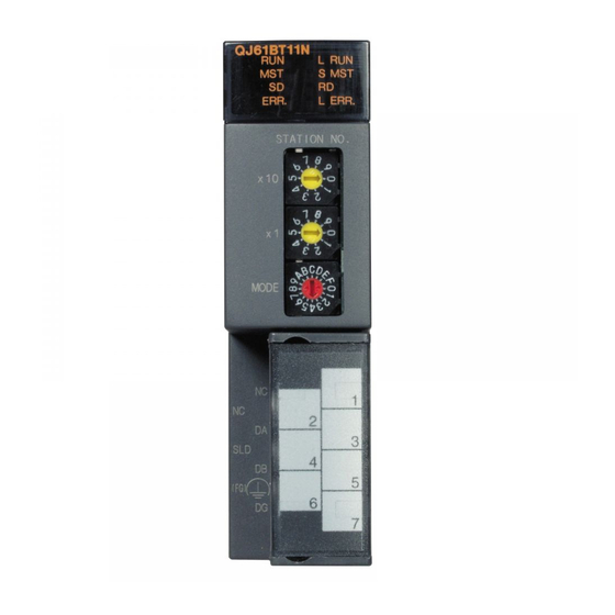
2 SYSTEM CONFIGURATION MELSEC-Q 2.2.3 How to check the function version The following describes how to check the function version. (1) How to check the function version of the QJ61BT11N (a) Checking the "SERIAL column of the rating plate" on the module side Serial No. -
Page 39: Cc-Link Version
2 SYSTEM CONFIGURATION MELSEC-Q 2.2.4 CC-Link version There are two types of CC-Link version, i.e., Ver.1 and Ver.2. (1) Definition of Ver.1.00 and Ver.1.10 Version 1.10 modules have a uniform station-to-station cable length of 20 cm or more by improving the restrictions on the conventional station-to-station cable length. -
Page 40: Specifications
3 SPECIFICATIONS MELSEC-Q 3 SPECIFICATIONS This section describes the specifications of the QJ61BT11N. For the general specifications of the QJ61BT11N, refer to the user's manual for the CPU module to be used. 3.1 Performance Specifications Table 3.1 lists the performance specifications of the OJ61BT11N. Table 3.1 Performance specifications Item Specification... - Page 41 3 SPECIFICATIONS MELSEC-Q Table 3.2 Number of link points for remote net ver.2 mode/remote net additional mode Item Specifications Remote I/O (RX, RY) : 8192 points Remote register (RWw) : 2048 points (master station remote device station/local station/intelligent device Maximum No. of link points per system station/standby master station) Remote register (RWr) : 2048 points (remote device station/local station/intelligent device station/standby...
-
Page 42: Maximum Overall Cable Distance (For Ver. 1.00)
3 SPECIFICATIONS MELSEC-Q 3.1.1 Maximum overall cable distance (for Ver. 1.00) The relationship between the transmission speed and the maximum overall cable distance is described below: (1) For a system consisting of only remote I/O stations and remote device stations Remote I/O station Remote I/O station Remote I/O station... - Page 43 3 SPECIFICATIONS MELSEC-Q (Example) When the transmission rate is 10 Mbps, and 43 remote I/O stations and remote device stations are connected using the CC-Link dedicated high performance cable, because the cable connecting the second and third stations is "35 cm (13.78 in.)", the maximum overall cable distance will be "80 cm (31.5 in.)".
-
Page 44: Maximum Overall Cable Distance (For Ver. 1.10)
3 SPECIFICATIONS MELSEC-Q 3.1.2 Maximum overall cable distance (for Ver. 1.10) The relation of the transmission speed and maximum overall cable distance when configuring the entire system with Version 1.10 modules and cable is shown below. Local station or Local station or Remote I/O station Remote I/O station Master station... -
Page 45: Cc-Link Dedicated Cable
3 SPECIFICATIONS MELSEC-Q 3.2 CC-Link Dedicated Cable Use the CC-Link dedicated cable for the CC-Link system. If a cable other than the CC- Link dedicated cable is used, the performance of the CC-Link system cannot be guaranteed. If you have any questions regarding the CC-Link dedicated cable, or if you wish to see its specifications, see the CC-Link Partner Association homepage http://www.cc- link.org/. - Page 46 3 SPECIFICATIONS MELSEC-Q MEMO 3 - 7 3 - 7...
-
Page 47: Functions
4 FUNCTIONS MELSEC-Q 4 FUNCTIONS This chapter explains the functions of QJ61BT11N, dividing them into four sections: "Basic Functions", "Functions for Improving System Reliability", "Handy Functions" and "Transient Transmission Functions". Some functions are unavailable depending on the mounted CPU. Refer to Appendix 6 for details. 4.1 Function List (1) Table 4.1 lists the "basic functions". - Page 48 4 FUNCTIONS MELSEC-Q (3) Table 4.3 lists the "handy functions". Table 4.3 List of the "handy functions" Item Description Reference section Remote device station initialization Performs initial setting of remote device station using GX Section 4.4.1 procedure registration function Developer. Issues events when the conditions set by GX Developer are Event issuance for the interrupt established and causes the PLC CPU to run an interrupt...
-
Page 49: Basic Functions
4 FUNCTIONS MELSEC-Q 4.2 Basic Functions This section explains the basic functions of the QJ61BT11N. 4.2.1 Communication with the remote I/O stations Two types of communication modes are available for the CC-Link system: remote net mode and remote I/O net mode. (1) Remote net mode In this mode, it is possible to communicate with all stations (remote I/O station, remote device station, local station, intelligent device station, and standby master... - Page 50 4 FUNCTIONS MELSEC-Q [Remote input] 2) The input status of a remote I/O station is stored automatically (for each link scan) in the master station's "remote input RX" buffer memory. 3) The input status stored in the "remote input RX" buffer memory is stored in the CPU device set with the automatic refresh parameters.
-
Page 51: Communication With The Remote Device Stations
4 FUNCTIONS MELSEC-Q 4.2.2 Communication with the remote device stations This section explains an overview of the communication between the master and the remote device stations. In the communication with remote device stations, the signals for handshaking with remote device stations (initial data request flag, error reset request flag, etc.) are communicated using remote input RX and remote output RX. - Page 52 4 FUNCTIONS MELSEC-Q [Data link startup] 1) When the PLC system is powered on, the network parameters in the PLC CPU are transferred to the master station, and the CC-Link system automatically starts up. [Remote input] 2) The remote input RX of a remote device station is stored automatically (for each link scan) in the master station's "remote input RX"...
- Page 53 4 FUNCTIONS MELSEC-Q [Remote output] 4) The on/off data of the CPU device set with the automatic refresh parameters is stored in the "remote output RY" buffer memory. 5) Remote output RY is automatically set to on/off (for each link scan) according to the output status stored in the "remote output RY"...
- Page 54 4 FUNCTIONS MELSEC-Q [Writing to the remote register RWw] 6) The transmission data of the CPU device set with the automatic refresh parameters is stored in the "remote register RWw" buffer memory. 7) The data stored in the "remote register RWw" buffer memory is automatically sent to the remote register RWw of each remote device station.
- Page 55 4 FUNCTIONS MELSEC-Q [Reading from the remote register (RWr)] 8) The remote register RWr data of a remote device station is automatically stored in the "remote register Rwr" buffer memory of the master station. 9) The remote register RWr data of a remote device station stored in the "remote register RWr"...
-
Page 56: Communication With The Local Stations
4 FUNCTIONS MELSEC-Q 4.2.3 Communication with the local stations This section explains an overview of the communication between the master and local stations. (1) Communication between the master and local stations by cyclic transmission Data communication between PLC CPUs can be performed in N:N mode using remote input RX and remote output RY (bit data used in local station systems) as well as remote register RWw and remote register RWr (word data for writing and reading used in local station systems). - Page 57 4 FUNCTIONS MELSEC-Q [Data link startup] 1) When the PLC system is powered on, the network parameters in the PLC CPU are transferred to the master station and the CC-Link system starts up automatically. [On/off data from a local station to the master station or other local stations] 2) The on/off data of the CPU device set with the automatic refresh parameters is stored in the "remote output RY"...
- Page 58 4 FUNCTIONS MELSEC-Q [On/off data from the master station to local stations] 6) The on/off data of the CPU device set with the automatic refresh parameters is stored in the "remote output RY" buffer memory of the master station. 7) The data in the "remote output RY" buffer memory is stored automatically (for each link scan) in the "remote input RX"...
- Page 59 4 FUNCTIONS MELSEC-Q [Word data from the master station to all local stations] 9) The word data of the CPU device set with the automatic refresh parameters is stored in the "remote register RWw" buffer memory of the master station. The remote register RWw is used as word data for writing in local station systems.
- Page 60 4 FUNCTIONS MELSEC-Q [Word data from a local station to the master and other local stations] 12) Word data set with the automatic refresh parameters is stored in the "remote register RWw" buffer memory of the local station. However, the data is stored only in the area corresponding to its own station number.
- Page 61 4 FUNCTIONS MELSEC-Q (2) Communication between the master and local stations by transient transmission Transient transmission sends and receives data in 1 : 1 mode by specifying the opposite party at an arbitrary timing. [Writing data to the buffer memory in a local station using the RIWT instruction] 1) Data to be written to the buffer memory in a local station is stored in the send buffer in the master module.
-
Page 62: Communication With The Intelligent Device Stations
4 FUNCTIONS MELSEC-Q 4.2.4 Communication with the intelligent device stations This section explains an overview of the communication between the master and intelligent device stations. (1) Communication between the master station and intelligent device stations by cyclic transmission Handshaking signals with intelligent device stations (positioning complete, positioning start. - Page 63 4 FUNCTIONS MELSEC-Q [Data link startup] 1) When the PLC system is powered on, the network parameters in the PLC CPU are transferred to the master station, and the CC-Link system automatically starts up. [Remote input] 2) The remote input RX of an intelligent device station is stored automatically (for each link scan) in the master station's "remote input RX"...
- Page 64 4 FUNCTIONS MELSEC-Q [Remote output] 4) The on/off data of the CPU device set with the automatic refresh parameters is stored in the "remote output RY" buffer memory. 5) Remote output RY of the intelligent device station is automatically set to on/off (for each link scan) according to the output status stored in the "remote output RY"...
- Page 65 4 FUNCTIONS MELSEC-Q [Writing to the remote register (RWw)] 6) The transmission data of the CPU device set with the automatic refresh parameters is stored in the "remote register RWw" buffer memory. 7) The data stored in the "remote register RWw" buffer memory is automatically sent to the remote register RWw of the intelligent device station.
- Page 66 4 FUNCTIONS MELSEC-Q [Reading from the remote register (RWr)] 8) The remote register RWr data of the intelligent device station is automatically stored in the "remote register Rwr" buffer memory of the master station. 9) The remote register RWr data of the intelligent device station stored in the "remote register RWr"...
- Page 67 4 FUNCTIONS MELSEC-Q (2) Communication between the master and intelligent device stations by transient transmission Transient transmission sends and receives data in 1 : 1 mode by specifying the opposite party at an arbitrary timing. [Writing data to the buffer memory in the intelligent device station using the RIWT instruction] 1) Data to be written to the buffer memory in an intelligent device station is stored in the send buffer in the master module.
-
Page 68: Parameter Setting With Gx Developer
4 FUNCTIONS MELSEC-Q 4.2.5 Parameter setting with GX Developer Using GX Developer makes the setting of the network parameters and automatic refresh parameters easier. The data link is automatically started if GX Developer is used to set the parameters. Using GX Developer to set the parameters has the following advantages: •... -
Page 69: Parameter Setting With Dedicated Instruction
4 FUNCTIONS MELSEC-Q 4.2.6 Parameter setting with dedicated instruction It is possible to use the RLPASET instruction to set the network parameters of the master station and start the data link. Using the RLPASET instruction to set the parameters has the following advantages: •... - Page 70 4 FUNCTIONS MELSEC-Q It is necessary to set I/O assignments for modules whose network parameters are set by the RLPASET instruction. In addition, do not use GX Developer to set the network parameters and automatic refresh parameters for modules whose network parameters are set by the RLPASET instruction.
-
Page 71: Functions For Improving System Reliability
4 FUNCTIONS MELSEC-Q 4.3 Functions for Improving System Reliability This section explains the functions for improving the reliability of the CC-Link system. 4.3.1 Disconnecting data link faulty stations and continuing the data link with only normal stations (Slave station cut-off function) This function disconnects remote stations, local stations, intelligent device stations, and a standby master station that have become data link faulty due to power off, and continues the data link among normal remote stations, local stations, intelligent device... -
Page 72: Automatically Reconnecting A Disconnected Data Link Faulty Station When It Returns To Normal
4 FUNCTIONS MELSEC-Q 4.3.2 Automatically reconnecting a disconnected data link faulty station when it returns to normal (Automatic return function) This function allows remote stations, local stations, intelligent device stations, and a standby master station that have been disconnected from the data link due to power off to automatically reconnect to the data link when they return to the normal status. -
Page 73: Continuing The Data Link When An Error Occurs In The Master Station Plc Cpu (Data Link Status Setting When The Master Station Plc Cpu Has An Error)
4 FUNCTIONS MELSEC-Q 4.3.3 Continuing the data link when an error occurs in the master station PLC CPU (Data link status setting when the master station PLC CPU has an error) This function sets the data link status when the master station PLC CPU falls into an error that stop the operation. -
Page 74: Retaining The Device Status Of A Data Link Faulty Station (Setting The Status Of Input Data From A Data Link Faulty Station)
4 FUNCTIONS MELSEC-Q 4.3.4 Retaining the device status of a data link faulty station (Setting the status of input data from a data link faulty station) This function sets the input (receiving) data from a data link faulty station. (1) Applicable input (receiving) data The following shows the applicable buffer memory areas. -
Page 75: Clearing Data In Case Of Plc Cpu Stop
4 FUNCTIONS MELSEC-Q 4.3.5 Clearing data in case of PLC CPU STOP (Slave station refresh/compulsory clear setting in case of PLC CPU STOP) This function compulsorily clears output (send) data to slave stations when the PLC CPU comes to STOP. Remote output RY refresh device setting in the automatic refresh parameter dialog box provides the following choices. - Page 76 4 FUNCTIONS MELSEC-Q POINT (1) Specifying compulsory clear disables compulsory output to slave stations at CPU STOP using GX Developer. (2) This setting is also valid when the TO instruction is used for RY refresh. (2) Setting method Set the "Operational setting" value in the network parameters using the GX Developer.
-
Page 77: Continuing The Data Link Even When The Master Station Is Faulty
4 FUNCTIONS MELSEC-Q 4.3.6 Continuing the data link even when the master station is faulty (Standby master function) This function enables the data link to continue working by switching to a standby master station (meaning a backup station for the master station) if a system down occurs in the master station due to a malfunction in the PLC CPU or power supply. - Page 78 4 FUNCTIONS MELSEC-Q Controlling: Controlling the data link of the CC-Link system Standby: Standing by in case the station controlling the data link of the CC-Link system becomes faulty. Standby master station Station number 1 Data link control by the master station Number of occupied stations: 1 Master station Intelligent device station...
- Page 79 4 FUNCTIONS MELSEC-Q Continued from the previous page Problem occurs in the standby master station Data link control by the master station Master station Station number 1 Standby master station Remote device station Intelligent device station Station number 2 Station number 4 Number of occupied stations: 2 Number of occupied stations: 1 Controlling...
- Page 80 4 FUNCTIONS MELSEC-Q (1) Overview of link data transmission when the standby master function is used The following shows an overview of link data transmission when the standby master function is used. (a) When the master station controls the data link 1) Master station output Standby master station (standby) Station number 1...
- Page 81 4 FUNCTIONS MELSEC-Q (b) When the master station is faulty and the standby master station is controlling the data link 1) Standby master station output Standby master station (controlling) Station number 1 Master station Remote Remote Remote Remote Remote I/O station input RX output RY input RX...
- Page 82 4 FUNCTIONS MELSEC-Q (c) When the master station has returned to system operation and the standby master station is controlling the data link 1) Standby master station output Master station (standby) Standby master station Station number 0 (controlling) Number of occupied stations: 1 Station number 0 Remote Remote...
- Page 83 4 FUNCTIONS MELSEC-Q (d) When the standby master station becomes faulty and the master station controls the data link 1) Master station output Master station (controlling) Standby master station Station number 1 Remote Remote Remote Remote input RX output RY input RX output RY Remote I/O station...
- Page 84 4 FUNCTIONS MELSEC-Q (2) Setting method Perform the setting using the GX Developer. (a) Setting the master station First, set "Type" in the network parameters. Master station that was down returns to system operation: Master station (Duplex function) Master station that was down does not return to system operation: Master station Next, set the "Standby master station No."...
- Page 85 4 FUNCTIONS MELSEC-Q (3) Precautions on using the standby master function (a) Only one standby master station exists in a single data link system. (b) The total number of stations is 64, including the standby master station. The number of stations that can be occupied by the standby master station is one or four.
- Page 86 4 FUNCTIONS MELSEC-Q (4) Link special relays/registers (SB and SW) relating to the standby master function The following explains the link special relays and registers relating to the standby master function. These are stored in the buffer memory. When the standby master station is controlling the data link, its applicability is basically identical to that of the master station.
- Page 87 4 FUNCTIONS MELSEC-Q Table 4.5 List of link special relays relating to the standby master function (2/2) Applicability : Applicable, : Not applicable) Number Name Description Master Local station Offline station Indicates whether a forced master switching request SB005D Forced master switching acknowledgement is complete or not.
- Page 88 4 FUNCTIONS MELSEC-Q (5) On/off timings of link special relays (SB) relating to the standby master function The following shows the on/off timings of the link special relays (SB) relating to the standby master function. SB70 (Master station information) SB7B (Host master/standby master operation status) SB5A (Master switching request acknowledgment)
- Page 89 4 FUNCTIONS MELSEC-Q (6) Program example when the standby master function (master station duplex function) is used A program example is created under the following conditions when the standby master function (master station duplex function) is used. (a) System configuration Standby master station Station number 1 Number of occupied stations: 1...
- Page 90 4 FUNCTIONS MELSEC-Q (d) Program example when standby master function (master station duplex function) is used Control start relay used when master station is operating....M10 Control start relay used when standby master station is operating ..M11 Control start relay when the master station is operating Initial device set Control start relay when the station...
-
Page 91: Handy Functions
4 FUNCTIONS MELSEC-Q 4.4 Handy Functions This section explains some handy functions of the QJ61BT11N. 4.4.1 Simplifying the initialization procedure registration of remote device stations (Remote device station initialization procedure registration function) The initial settings of remote device stations, which in previous models were done using the sequence program, can now be performed using the GX Developer for registration to the PLC CPU. - Page 92 4 FUNCTIONS MELSEC-Q 2) Execute Flag Set whether or not to execute the specified initialization procedure. Setting range: Execute Only set (use as a memo when the execution conditions are the same as when the execution flag is set as "Execute", but the content of execution is different.) Default: Execute...
- Page 93 4 FUNCTIONS MELSEC-Q 9) Details of execution "Write Data" Set the contents of the initial settings. Setting range: When RY is selected ON/OFF When RWw is selected 0 to 65535 (Decimal), 0 to FFFF (Hexadecimal) (2) Validate initial settings Before creating a program for communication with remote device stations, create a program to validate the initial settings that use SB0D (remote device station initialization procedure registration instruction) and SB5F (completion status of remote device station initialization procedure).
-
Page 94: Performing High-Speed Processing (Event Issuance For The Interrupt Program)
4 FUNCTIONS MELSEC-Q 4.4.2 Performing high-speed processing (Event issuance for the interrupt program) This function issues events (signals to execute an interrupt program) according to factors such as the on/off status of specified RX, RY and SB devices and the match/mismatch status of specified RWr and SW device data, in order to allow the PLC CPU to execute the interrupt program. - Page 95 4 FUNCTIONS MELSEC-Q 5) Interrupt condition Set the conditions under which events are issued. Setting range: When RX, SB or RY is selected ON/OFF When RWr or SW is selected Equal/Unequal 6) Word device Set the conditions under which events are issued when RWw or SW is selected.
- Page 96 4 FUNCTIONS MELSEC-Q 4) "Start SI No." on the intelli. unit side Set the smallest number for intelligent function module interrupt pointers specified in "Interrupt (SI) No." of the "Interrupt settings" in the Network parameters. Setting range: 0 to 15 (3) Simulation of the interrupt program When the event issuance conditions are established in the master station using the GX Developer, the interrupt program is executed even when the...
-
Page 97: Enabling The Data Link Simply By Powering On (Automatic Cc-Link Startup)
4 FUNCTIONS MELSEC-Q 4.4.3 Enabling the data link simply by powering on (Automatic CC-Link startup) By mounting the QJ61BT11N in the system configuration including the remote device station and intelligent device station as well as the remote I/O station, CC-Link startup and complete data refresh can be performed by just turning on the power, without creating a sequence program. - Page 98 4 FUNCTIONS MELSEC-Q Content of buffer memory size specification for intelligent device station Send buffer 64 words Receive buffer 64 words Automatic update buffer 128 words POINT (1) Perform an automatic CC-Link startup in the remote net ver. 1 mode. (2) If an automatic CC-Link startup is performed on a system that includes a local station, the local station will occupy one station during operation.
-
Page 99: Communicating With Intelligent Device Stations (Remote Net Mode)
4 FUNCTIONS MELSEC-Q 4.4.4 Communicating with intelligent device stations (Remote net mode) The remote net mode allows communication with all stations (remote I/O stations, remote device stations, local stations, intelligent device stations, and standby master stations). Furthermore, it allows not only cyclic transfer, but also transient transmission, which transfers data at an arbitrary timing, to intelligent and local stations. -
Page 100: Speeding Up The Response From Remote I/O Stations (Remote I/O Net Mode)
4 FUNCTIONS MELSEC-Q 4.4.5 Speeding up the response from remote I/O stations (Remote I/O net mode) The remote I/O net mode can be used for a system consisting of only the master station and remote I/O stations. The remote I/O net mode allows cyclic transmission at high speed, thus shortening the link scan time. -
Page 101: Creating A Program That Contains Modules To Be Added In The Future (Reserved Station Function)
4 FUNCTIONS MELSEC-Q 4.4.6 Creating a program that contains modules to be added in the future (Reserved station function) This function prevents remote stations, local stations, intelligent device stations, and a standby master station that are not actually connected (but to be connected in the future) from being treated as "data link faulty stations"... -
Page 102: Powering Off A Station In Operation Without Error Detection
4 FUNCTIONS MELSEC-Q 4.4.7 Powering off a station in operation without error detection (Error invalid station setting function) This function prevents remote stations, local stations, intelligent device stations, and a standby master station that are powered off in the system configuration from being treated as "data link faulty stations"... -
Page 103: Synchronizing The Link Scan With The Sequence Scan (Scan Synchronous Function)
4 FUNCTIONS MELSEC-Q 4.4.8 Synchronizing the link scan with the sequence scan (Scan synchronous function) This function selects whether or not the link scan should be synchronized with the sequence scan. (1) Synchronous mode Performs data linking using the scan that is synchronized with the sequence program. - Page 104 4 FUNCTIONS MELSEC-Q (4) Data flows in synchronous and asynchronous modes The data flows in both the synchronous and asynchronous modes are explained using examples of communications between the master station and remote I/O stations. (a) Data flow in the asynchronous mode PLC CPU (Sequence scan) Master station buffer memory...
- Page 105 4 FUNCTIONS MELSEC-Q (b) Data flow in the synchronous mode 1) Sequence scan > Link scan PLC CPU (Sequence scan) Master station buffer memory (Remote input RX) Link scan Response time of the first station Response time of the corresponding station Response time of the final station Responses from remote I/O stations...
- Page 106 4 FUNCTIONS MELSEC-Q 2) Sequence scan < Link scan PLC CPU (Sequence scan) Master station buffer memory (Remote input RX) Link scan Response time of the first station Response time of the corresponding station Response time of the final station Responses from remote I/O stations Input 1)
-
Page 107: Replacing Modules Without Error Detection (Temporary Error Invalid Station Setting Function)
4 FUNCTIONS MELSEC-Q 4.4.9 Replacing modules without error detection (Temporary error invalid station setting function) This function prevents remote stations, local stations, intelligent device stations, and the standby master station that are specified with the GX Developer from being treated as "data link faulty stations"... -
Page 108: Checking Operations For Each Local Station (Data Link Stop/Restart)
4 FUNCTIONS MELSEC-Q 4.4.10 Checking operations for each local station (Data link stop/restart) This function stops and restarts local data links. If the data link of the master station is stopped, the data link of the entire system stops. [Setting method] Set the "CC-Link / CC-Link/LT Diagnostics"... -
Page 109: Station Number Overlap Checking Function
4 FUNCTIONS MELSEC-Q 4.4.11 Station number overlap checking function This function investigates the status of connected stations and checks for the overlapping numbers of number of occupied stations and whether or not more than one station whose station number setting is 0 exists in the system. (1) Number of occupied station number overlap checking Checks whether or not occupied station numbers duplicate. -
Page 110: Multiple Plc System Support
4 FUNCTIONS MELSEC-Q 4.4.12 Multiple PLC system support This function allows monitoring and reading/writing programs from/to any CPU in a multiple PLC system mounted with the QJ61BT11N via AJ65BT-G4-S3 or other station CPUs. This is illustrated by the following example. It is possible to monitor CPU4 of the local station from peripheral device A connected to the AJ65BT-G4-S3 and read the programs of CPU2 of the master station from peripheral device B connected to CPU3 of the local station. -
Page 111: Reducing The Reserved Points Of The Remote I/O Stations (Remote I/O Station Points Setting)
4 FUNCTIONS MELSEC-Q 4.4.13 Reducing the reserved points of the remote I/O stations (Remote I/O station points setting) The points of each remote I/O station can be set to 8, 16 or 32 points. This saves the refresh device points of the PLC CPU. The remote I/O station points setting can be used in the remote net ver. - Page 112 4 FUNCTIONS MELSEC-Q [Setting method] Using GX Developer, make setting by choosing "Station information setting" - "Remote station points" in the network parameter dialog box. For more details on the setting, see Sections 6.3 to 6.5. (1) Precautions for setting the remote I/O station points The number of parameter-set remote I/O station points should be equal to or greater than the number of I/O points of the mounted remote I/O stations.
-
Page 113: Increasing The Number Of Cyclic Points (Remote Net Ver.2 Mode)
4 FUNCTIONS MELSEC-Q 4.4.14 Increasing the number of cyclic points ( Remote net ver.2 mode This function increases the number of cyclic points. When increasing the number of cyclic points, select one from the following two modes. Remote net ver.2 mode ....Mode suitable for configuring a new system Remote net additional mode.. - Page 114 4 FUNCTIONS MELSEC-Q (1) Remote net ver.2 mode This mode is designed to configure a new system. The number of cyclic points can be increased as indicated below. Per station, RX/RY can be increased to up to 128 points and RWw/RWr to up to 32 points.
- Page 115 4 FUNCTIONS MELSEC-Q Remote net additional mode This mode is designed for use when slave stations including a ver. 2 compatible station is added to the existing ver. 1 system. The program of the existing system can be used as is. Local station Remote device station Remote device station...
- Page 116 4 FUNCTIONS MELSEC-Q (3) Precautions for cyclic points increase setting (a) Whether system can be configured or not The following table indicates whether cyclic transmission can be made or not in each station. QJ61BT11 Slave station AJ61BT11, A1SJ61BT11, QJ61BT11N AJ61QBT11, Remote station A1SJ61QBT11, Intelligent device...
- Page 117 4 FUNCTIONS MELSEC-Q 2: When the master station is in the remote net additional mode of the QJ61BT11N and the local station is in the remote net ver. 2 mode of the QJ61BT11N, a link is performed as shown in the following areas. Local station Standby master station Local station...
- Page 118 4 FUNCTIONS MELSEC-Q (b) Whether send/receive is enabled or not The following table indicates whether send/receive of cyclic data is enabled or not. QJ61BT11N Receive station Master station Ver.2 mode Additional mode Ver.1 mode Ver. 2 Ver. 1 Ver. 2 Ver.
- Page 119 4 FUNCTIONS MELSEC-Q Remote QJ61BT11N QJ61BT11 Intelligent device Remote device Master Local station statio Local station station station station Ver.2 mode Additional mode Ver1 mode Ver.1 Ver.1 Ver.2 Ver.1 Ver.2 Ver.1 Ver.1 Ver. 2 Ver. 1 Ver. 2 Ver. 1 Ver.
- Page 120 4 FUNCTIONS MELSEC-Q (4) Mismatch in number of points between parameter-set expanded cyclic setting and installation status If there is a mismatch in the number of points between the parameter-set expanded cyclic setting and installation status, the QJ61T11N stores the error code into SW0069.
-
Page 121: Transient Transmission Functions
4 FUNCTIONS MELSEC-Q 4.5 Transient Transmission Functions This section explains the transient transmission functions. 4.5.1 Performing transient transmission (Dedicated instructions) The following dedicated instructions can be used for transient transmission. Reference Applicable station Instruction Description section Reads data from the buffer memory of a specified Appendix RIRD station or a PLC CPU device of a specified... -
Page 122: Data Link Processing Time
5 DATA LINK PROCESSING TIME MELSEC-Q 5 DATA LINK PROCESSING TIME This chapter explains the data link processing time such as the link scan time and transmission delay time. 5.1 Link Scan Time This section explains the CC-Link scan time. The following describes the method for calculating the normal value and maximum value for the remote net mode or remote I/O net mode. - Page 123 5 DATA LINK PROCESSING TIME MELSEC-Q EX: Constant (only when remote net ver. 2 mode or remote net additional mode is used) 50 + total in the following table Number of occupied Occupies Occupies Occupies Occupies stations 1 station 2 stations 3 stations 4 stations Expanded cyclic setting...
- Page 124 5 DATA LINK PROCESSING TIME MELSEC-Q (2) For remote I/O net mode LS = BT {27 + (NI 4.8) + (N 30) + (ni 4.8)} + ST + F [µ s] BT: Constant (transmission rate) Transmission rate 156 kbps 625 kbps 2.5 Mbps 5 Mbps 10 Mbps 51.2 12.8...
-
Page 125: Transmission Delay Time
5 DATA LINK PROCESSING TIME MELSEC-Q 5.2 Transmission Delay Time This section explains the transmission delay time (the time until data is transmitted). 5.2.1 Master station remote I/O station (1) Master station (RX) remote I/O station (input) This indicates the time from the moment the signal is input to the remote I/O station until the CPU device turns ON (OFF). - Page 126 5 DATA LINK PROCESSING TIME MELSEC-Q (b) Synchronous mode 2 + Remote I/O station response time [ms] SM: Master station sequence program scan time LS: Link scan time (see Section 5.1) (LS/SM) value when fractions following the decimal point are rounded up to the next whole number (Example) When the sequence scan time for the master station is 20 ms, the link scan time is 3 ms and the remote I/O station response time is 1.5 ms.
- Page 127 5 DATA LINK PROCESSING TIME MELSEC-Q [Maximum value] (a) Asynchronous mode SM + LS 2 + Remote I/O station response time [ms] SM: Master station sequence program scan time LS: Link scan time (see Section 5.1) (Example) When the sequence scan time for the master station is 20 ms, the link scan time is 3 ms and the remote I/O station response time is 1.5 ms.
- Page 128 5 DATA LINK PROCESSING TIME MELSEC-Q 5.2.2 Master station remote device station (Ver. 1 compatible slave station) (1) Master station (RX) remote device station (RX) This indicates the time from the moment the signal is input to the remote device station until the CPU device turns ON (OFF).
- Page 129 5 DATA LINK PROCESSING TIME MELSEC-Q (Example) When the sequence scan time for the master station is 20 ms, the link scan time is 3 ms and the remote device station processing time is 1.5 ms. 1 + Remote device station processing time [ms] = (20 1 + 1.5 = 21.5 [ms]...
- Page 130 5 DATA LINK PROCESSING TIME MELSEC-Q (b) Synchronous mode n + LS + Remote device station processing time [ms] SM: Master station sequence program scan time LS: Link scan time (see Section 5.1) (LS/SM)value when fractions following the decimal point are rounded up to the next whole number (Example) When the sequence scan time for the master station is 20 ms, the link scan time is 3 ms and the remote device station processing time is 1.5 ms.
- Page 131 5 DATA LINK PROCESSING TIME MELSEC-Q (3) Master station (RWr) remote device station (RWr) This indicates the time from the moment the signal is input to the remote device station until the data for the CPU device is changed. [Expression] [Normal value] (a) Asynchronous mode SM + LS...
- Page 132 5 DATA LINK PROCESSING TIME MELSEC-Q (4) Master station (RWw) remote device station (RWw) This indicates the time from the moment data is set to the CPU device until the data for the remote device station is changed. [Expression] [Normal value] (a) Asynchronous mode SM + LS 1 + Remote device station processing time [ms]...
- Page 133 5 DATA LINK PROCESSING TIME MELSEC-Q 5.2.3 Master station remote device station (Ver. 2 compatible slave station) (1) Master station (RX) remote device station (RX) This indicates the time from the moment the signal is input to the remote device station until the CPU device turns ON (OFF).
- Page 134 5 DATA LINK PROCESSING TIME MELSEC-Q [Maximum value] (a) Asynchronous mode SM + LS m + Remote device station processing time [ms] SM: Master station sequence program scan time LS: Link scan time (see Section 5.1) m: Constant (expanded cyclic setting) Expanded cyclic setting single double...
- Page 135 5 DATA LINK PROCESSING TIME MELSEC-Q (2) Master station (RY) remote device station (RY) This indicates the time from the moment the CPU device turns ON (OFF) until the remote device station output turns ON (OFF). [Expression] [Normal value] (a) Asynchronous mode SM + LS m + 1) + Remote device station processing time [ms] SM: Master station sequence program scan time...
- Page 136 5 DATA LINK PROCESSING TIME MELSEC-Q [Maximum value] (a) Asynchronous mode SM + LS m + 1) + Remote device station processing time [ms] SM: Master station sequence program scan time LS: Link scan time (see Section 5.1) m: Constant (expanded cyclic setting) Expanded cyclic setting single double...
- Page 137 5 DATA LINK PROCESSING TIME MELSEC-Q (3) Master station (RWr) remote device station (RWr) This indicates the time from the moment the signal is input to the remote device station until the data for the CPU device is changed. [Expression] [Normal value] (a) Asynchronous mode SM + LS...
- Page 138 5 DATA LINK PROCESSING TIME MELSEC-Q [Maximum value] (a) Asynchronous mode SM + LS m + Remote device station processing time [ms] SM: Master station sequence program scan time LS: Link scan time (see Section 5.1) m: Constant (expanded cyclic setting) Expanded cyclic setting single double...
- Page 139 5 DATA LINK PROCESSING TIME MELSEC-Q (4) Master station (RWw) remote device station (RWw) This indicates the time from the moment data is set to the CPU device until the data for the remote device station is changed. [Expression] [Normal value] (a) Asynchronous mode SM + LS m + 1) + Remote device station processing time [ms]...
- Page 140 5 DATA LINK PROCESSING TIME MELSEC-Q [Maximum value] (a) Asynchronous mode SM + LS m + 1) + Remote device station processing time [ms] SM: Master station sequence program scan time LS: Link scan time (see Section 5.1) m: Constant (expanded cyclic setting) Expanded cyclic setting single double...
- Page 141 5 DATA LINK PROCESSING TIME MELSEC-Q 5.2.4 Master station local station (Ver. 1 compatible slave station) (1) Master station (RX) local station (RY) This indicates the time from the moment the local station CPU device turns ON (OFF) until the master station CPU device turns ON (OFF). [Expression] [Normal value] (a) Asynchronous mode...
- Page 142 5 DATA LINK PROCESSING TIME MELSEC-Q (b) Synchronous mode 3 + SL [ms] SM: Master station sequence program scan time SL: Local station sequence program scan time LS: Link scan time (see Section 5.1) (LS/SM)value when fractions following the decimal point are rounded up to the next whole number (Example) When the master station sequence scan time is 20 ms, the link scan time is 3 ms and the local station sequence scan time is 10 ms.
- Page 143 5 DATA LINK PROCESSING TIME MELSEC-Q [Maximum value] (a) Asynchronous mode SM + LS 2 + SL [ms] SM: Master station sequence program scan time LS: Link scan time (see Section 5.1) SL: Local station sequence program scan time (Example) When the master station sequence scan time is 20 ms, the link scan time is 3 ms and the local station sequence scan time is 10 ms.
- Page 144 5 DATA LINK PROCESSING TIME MELSEC-Q (b) Synchronous mode 2 + SL [ms] SM: Master station sequence program scan time SL: Local station sequence program scan time LS: Link scan time (see Section 5.1) (LS/SM)value when fractions following the decimal point are rounded up to the next whole number (Example) When the master station sequence scan time is 20 ms, the link scan time is 3 ms and the local station sequence scan time is 10 ms.
- Page 145 5 DATA LINK PROCESSING TIME MELSEC-Q (4) Master station (RWw) → local station (RWr) This indicates the time from the moment data is set to the master station CPU device until the data is stored in the local station CPU device. [Expression] [Normal value] (a) Asynchronous mode...
- Page 146 5 DATA LINK PROCESSING TIME MELSEC-Q (b) Synchronous mode n + LS 2 + SL [ms] SM: Master station sequence program scan time LS: Link scan time (see Section 5.1) SL: Local station sequence program scan time (LS/SM)value when fractions following the decimal point are rounded up to the next whole number (Example) When the master station sequence scan time is 20 ms, the link scan time is 3 ms and the local station sequence scan time is 10 ms.
- Page 147 5 DATA LINK PROCESSING TIME MELSEC-Q 5.2.5 Master station local station (Ver. 2 compatible slave station) (1) Master station (RX) local station (RY) This indicates the time from the moment the local station CPU device turns ON (OFF) until the master station CPU device turns ON (OFF). [Expression] [Normal value] (a) Asynchronous mode...
- Page 148 5 DATA LINK PROCESSING TIME MELSEC-Q [Maximum value] (a) Asynchronous mode SM + LS m + 1) + SL [ms] SM: Master station sequence program scan time LS: Link scan time (see Section 5.1) SL: Local station sequence program scan time m: Constant (expanded cyclic setting) Expanded cyclic setting single...
- Page 149 5 DATA LINK PROCESSING TIME MELSEC-Q (2) Master station (RY) local station (RX) This indicates the time from the moment the master station CPU device turns ON (OFF) until the local station CPU device turns ON (OFF). [Expression] [Normal value] (a) Asynchronous mode SM + LS m + 1) + SL [ms]...
- Page 150 5 DATA LINK PROCESSING TIME MELSEC-Q [Maximum value] (a) Asynchronous mode SM + LS m + 1) + SL [ms] SM: Master station sequence program scan time LS: Link scan time (see Section 5.1) SL: Local station sequence program scan time m: Constant (expanded cyclic setting) Expanded cyclic setting single...
- Page 151 5 DATA LINK PROCESSING TIME MELSEC-Q (3) Master station (RWr) local station (RWw) This indicates the time from the moment data is set to the local station CPU device until the data is stored in the master station CPU device. [Expression] [Normal value] (a) Asynchronous mode...
- Page 152 5 DATA LINK PROCESSING TIME MELSEC-Q [Maximum value] (a) Asynchronous mode SM + LS m + 1) + SL [ms] SM: Master station sequence program scan time LS: Link scan time (see Section 5.1) SL: Local station sequence program scan time m: Constant (expanded cyclic setting) Expanded cyclic setting single...
- Page 153 5 DATA LINK PROCESSING TIME MELSEC-Q (4) Master station (RWw) → local station (RWr) This indicates the time from the moment data is set to the master station CPU device until the data is stored in the local station CPU device. [Expression] [Normal value] (a) Asynchronous mode...
- Page 154 5 DATA LINK PROCESSING TIME MELSEC-Q [Maximum value] (a) Asynchronous mode SM + LS m + 1) + SL [ms] SM: Master station sequence program scan time LS: Link scan time (see Section 5.1) SL: Local station sequence program scan time m: Constant (expanded cyclic setting) Expanded cyclic setting single...
-
Page 155: Master Station Intelligent Device Station
5 DATA LINK PROCESSING TIME MELSEC-Q 5.2.6 Master station intelligent device station The transmission delay time between the master station and an intelligent device station varies by the type of intelligent device station used. See the User's Manual for the intelligent device module to be used. 5 - 34 5 - 34... -
Page 156: Processing Time For Dedicated Instructions
5 DATA LINK PROCESSING TIME MELSEC-Q 5.3 Processing Time for Dedicated Instructions This indicates the dedicated instruction processing time (the time from the moment an instruction is issued until a response is received). 5.3.1 Master station local station (1) Master station local station This indicates the time from the moment an instruction is issued by the master station until a response from the local station is received. - Page 157 5 DATA LINK PROCESSING TIME MELSEC-Q (Example) When the PLC CPU type is Q06HCPU, the transmission rate is 10 Mbps, the link scan time is 5 ms and the write points are 20 words (buffer memory in the CC-Link). OT + LS [BC + {(write points + 16)/72} 1.13] [ms] = 0.5 + 5...
- Page 158 5 DATA LINK PROCESSING TIME MELSEC-Q (Example) When the PLC CPU type is Q06HCPU, the transmission rate is 10 Mbps, the link scan time is 5ms and the write points are 20 words (buffer memory in the CC-Lnik). OT + LS [BC + {(write points + 16)/16} 1.067] [ms] = 0.5 + 5...
-
Page 159: Local Station Local Station
5 DATA LINK PROCESSING TIME MELSEC-Q 5.3.2 Local station local station (1) Local station local station This indicates the time from the moment an instruction is executed by one local station until a response from another local station is received. [Expression] [Maximum value] (a) RIRD instruction... -
Page 160: Master Station Intelligent Device Station
5 DATA LINK PROCESSING TIME MELSEC-Q 5.3.3 Master station intelligent device station (1) Master station intelligent device station This indicates the time from the moment an instruction is issued by the master station and a response from an intelligent device station is received. [Expression] [Maximum value] (a) RIRD instruction... -
Page 161: Link Refresh Time
5 DATA LINK PROCESSING TIME MELSEC-Q 5.4 Link Refresh Time This section indicates link refresh time (increase of END processing time at the PLC CPU). 5.4.1 Master station/local station This section indicates the link refresh time of the master/local station. (1) Remote net ver. - Page 162 5 DATA LINK PROCESSING TIME MELSEC-Q KM2, KM3 : Constant 1) When QJ61BT11N is mounted on main base unit Constant ( 10 ( 10 CPU type Q00JCPU 0.91 – Q00CPU 0.83 – Q01CPU 0.79 – Q02CPU 0.48 0.32 Q02HCPU, Q06HCPU, Q12HCPU, Q25HCPU, Q12PHCPU, Q25PHCPU 0.43 0.14 2) When QJ61BT11N is mounted on extension base unit...
- Page 163 5 DATA LINK PROCESSING TIME MELSEC-Q (2) Remote net additional mode [Expression] KM1 + KM2 [{(RX + RX2) + (RY + RY2) + SB + (RWw + RWw2) 16 + (RWr + RWr2) 16 + (SW 16)} / 16] + αE [ms] αE = KM3 [(RX + RX2) + (RY + RY2) + SB + (RWw + RWw2) 16 + (RWr +...
- Page 164 5 DATA LINK PROCESSING TIME MELSEC-Q KM2, KM3 : Constant 1) When QJ61BT11N is mounted on main base unit Constant ( 10 ( 10 CPU type Q02CPU 0.48 0.32 Q02HCPU, Q06HCPU, Q12HCPU, Q25HCPU 0.43 0.14 2) When QJ61BT11N is mounted on extension base unit Constant ( 10 ( 10...
-
Page 165: Station Status At Error Occurrence
5 DATA LINK PROCESSING TIME MELSEC-Q 5.5 Station Status at Error Occurrence This section explains the status of each station at error occurrence. 5.5.1 Status of the master station, standby master station (when the master station is operating) and remote I/O station at error occurrence Table 5.1 lists the operation of the master station, standby master station (when the master station is operating) and remote I/O station upon the occurrence of an error. -
Page 166: Status Of The Remote Device Station, Local Station, Standby Master Station (When The Local Station Is Operating) And Intelligent Device Station At Error Occurrence
5 DATA LINK PROCESSING TIME MELSEC-Q 5.5.2 Status of the remote device station, local station, standby master station (when the local station is operating) and intelligent device station at error occurrence Table 5.2 lists the status of the remote device station, local station, standby master station (when the local station is operating) and intelligent device station at error occurrence. -
Page 167: Parameter Settings
6 PARAMETER SETTINGS MELSEC-Q 6 PARAMETER SETTINGS This chapter explains the parameter settings that are required to perform data link with the CC-Link. 6.1 Procedure from Parameter Settings to Data Link Startup The following explains the procedure from setting the parameters to starting the data link. -
Page 168: Procedure From Parameter Settings To Data Link Startup With Gx Developer
6 PARAMETER SETTINGS MELSEC-Q 6.1.2 Procedure from parameter settings to data link startup with GX Developer Follow the procedure below from parameter settings to data link startup: GX Developer PLC CPU Master station The GX Developer is used CC-Link system to create the network Parameter memory parameter area... -
Page 169: Parameter Setting Items
6 PARAMETER SETTINGS MELSEC-Q 6.2 Parameter Setting Items Table 6.1 lists the items to be stored in the master station parameter memory. Table 6.1 Parameter setting items (1/2) Standby Reference Master Local master Setting item Description section station station station Sets the input data status from the data link disorder station. - Page 170 6 PARAMETER SETTINGS MELSEC-Q Table 6.1 Parameter setting items (2/2) Standby Reference Master Local Setting item Description master section station station station Sets the type of the connected remote station, local station, intelligent device station and standby master station. Default value : Ver.1 remote I/O station, occupies 1 station, station number 1 to Ver.1 remote I/O station, occupies 1 station, station number 64...
-
Page 171: Example Of Parameter Settings With Gx Developer (Remote Net Ver.1 Mode)
6 PARAMETER SETTINGS MELSEC-Q 6.3 Example of Parameter Settings with GX Developer (Remote net ver.1 mode) This section explains the parameter settings using the GX Developer. For more details on the GX Developer operation, refer to the GX Developer Operating Manual. The explanations in this section are based on the following example of the system configuration. - Page 172 6 PARAMETER SETTINGS MELSEC-Q (c) Set the Parameter name using "Operational settings." (Even if the Parameter name is not set, this will not affect the operation of the CC-Link system). Default value : None Setting range: 8 characters or less Example) Set "CC-LinkM".
- Page 173 6 PARAMETER SETTINGS MELSEC-Q (f) Set the station type using "Type". Default value : Master station Setting range: Master station Master station (Duplex function) Local station Standby master station Example) Set to Master station. (g) Set the CC-Link mode using "Mode". Default value : Remote net(Ver.1 mode) Setting range: Remote net(Ver.1 mode) Remote net(Ver.2 mode)
- Page 174 6 PARAMETER SETTINGS MELSEC-Q (n) Set the link scan interval using "Delay information settings". Default value : 0 (Not specified) Setting range: 0 to 100 (Unit: 50 µ s) Example) Set to 10 (500 µ s). (o) Set the station data using "Station information settings". Default value : Remote I/O station, single, Occupies 1 station, 32 points, or no setting for reserved stations/error invalid.
- Page 175 6 PARAMETER SETTINGS MELSEC-Q (3) The following shows the results of the communication buffer and automatic update buffer assignments. 1000 2000 First module (station number 4) First module (station number 4) Intelligent device station Intelligent device station Send buffer Automatic update buffer 103F 207F 1040...
-
Page 176: Master Station Automatic Refresh Parameter Settings
6 PARAMETER SETTINGS MELSEC-Q 6.3.2 Master station automatic refresh parameter settings (1) The following shows an example of the parameter settings. See (2) for actual settings. (2) Set the automatic refresh parameters using the following procedure. (a) Set the remote input (RX) refresh device using "Remote input (RX)". Default value : None Setting range: Device name - Select from X, M, L, B, D, W, R or Device number - Within the range of the device... - Page 177 6 PARAMETER SETTINGS MELSEC-Q (d) Set the remote register (RWw) refresh device using "Remote register (RWw)". Default value : None Setting range: Device name - Select from M, L, B, T, C, ST, D, W, R, or ZR. Device number - Within the range of the device points that the CPU has.
-
Page 178: Local Station Network Parameter Settings
6 PARAMETER SETTINGS MELSEC-Q 6.3.3 Local station network parameter settings (1) The following describes an example of the parameter settings. See (2) for actual settings. (2) Set the network parameters using the following procedure. (a) Set the "No. of boards in module " for which the network parameters are to be set. - Page 179 6 PARAMETER SETTINGS MELSEC-Q (d) Set the Parameter name using "Operational settings". (Even if the Parameter name is not set, this will not affect the operation of the CC-Link system). Default value : None Setting range: 8 characters or less Example) Set "CC-LinkL".
- Page 180 6 PARAMETER SETTINGS MELSEC-Q (g) Set the number of occupied local stations using "Number of occupied stations". Default value : Occupies 1 station Setting range: Occupies 1 station Occupies 2 stations Occupies 3 stations Occupies 4 stations Example) Set to Occupies 4 stations (h) Set the CC-Link mode using "Mode".
-
Page 181: Local Station Automatic Refresh Parameter Settings
6 PARAMETER SETTINGS MELSEC-Q 6.3.4 Local station automatic refresh parameter settings (1) The following describes an example of the parameter settings. See (2) for actual settings. (2) Set the automatic refresh parameters using the following procedure. (a) Set the remote input (RX) refresh device using "Remote input (RX)". Default value : None Setting range: Device name - Select from X, M, L, B, D, W, R or Device number - Within the range of the device... - Page 182 6 PARAMETER SETTINGS MELSEC-Q (d) Set the remote register (RWw) refresh device using "Remote register (RWw)". Default value : None Setting range: Device name - Select from M, L, B, T, C, ST, D, W, R, or ZR. Device number - Within the range of the device points that the CPU has.
-
Page 183: Example Of Parameter Settings With Gx Developer (Remote Net Ver.2 Mode)
6 PARAMETER SETTINGS MELSEC-Q 6.4 Example of Parameter Settings with GX Developer (Remote net ver.2 mode) This section explains the parameter settings using the GX Developer. For more details on the GX Developer operation, refer to the GX Developer Operating Manual. The explanations in this section are based on the following example of the system configuration. - Page 184 6 PARAMETER SETTINGS MELSEC-Q (c) Set the Parameter name using "Operational settings." (Even if the Parameter name is not set, this will not affect the operation of the CC-Link system). Default value : None Setting range: 8 characters or less Example) Set "CC-LinkM".
- Page 185 6 PARAMETER SETTINGS MELSEC-Q (f) Set the station type using "Type". Default value : Master station Setting range: Master station Master station (Duplex function) Local station Standby master station Example) Set to Master station. (g) Set the CC-Link mode using "Mode". Default value : Remote net(Ver.1 mode) Setting range: Remote net(Ver.1 mode) Remote net(Ver.2 mode)
- Page 186 6 PARAMETER SETTINGS MELSEC-Q (n) Set the link scan interval using "Delay information settings". Default value : 0 (Not specified) Setting range: 0 to 100 (Unit: 50 µ s) Example) Set to 10 (500 µ s). (o) Set the station data using "Station information settings". Default value : Ver.1 Remote I/O station, single, Occupies 1 station, 32 points, or no setting for reserved stations/error invalid.
- Page 187 6 PARAMETER SETTINGS MELSEC-Q Intelligent buffer select (word) - No setting Send 0, 64 to 4096 Receive 0, 64 to 4096 Automatic 0, 128 to 4096 Example) Set the station data according to the system configuration specified in Section 6.4. (3) The following shows the results of the communication buffer and automatic update buffer assignments.
-
Page 188: Master Station Automatic Refresh Parameter Settings
6 PARAMETER SETTINGS MELSEC-Q 6.4.2 Master station automatic refresh parameter settings (1) The following shows an example of the parameter settings. See (2) for actual settings. (2) Set the automatic refresh parameters using the following procedure. (a) Set the remote input (RX) refresh device using "Remote input (RX)". Default value : None Setting range: Device name - Select from X, M, L, B, D, W, R or Device number - Within the range of the device... - Page 189 6 PARAMETER SETTINGS MELSEC-Q (d) Set the remote register (RWw) refresh device using "Remote register (RWw)". Default value : None Setting range: Device name - Select from M, L, B, T, C, ST, D, W, R, or ZR. Device number - Within the range of the device points that the CPU has.
-
Page 190: Local Station Network Parameter Settings
6 PARAMETER SETTINGS MELSEC-Q 6.4.3 Local station network parameter settings (1) The following describes an example of the parameter settings. See (2) for actual settings. (2) Set the network parameters using the following procedure. (a) Set the "No. of boards in module" for which the network parameters are to be set. - Page 191 6 PARAMETER SETTINGS MELSEC-Q (d) Set the Parameter name using "Operational settings". (Even if the Parameter name is not set, this will not affect the operation of the CC-Link system). Default value : None Setting range: 8 characters or less Example) Set "CC-LinkL".
- Page 192 6 PARAMETER SETTINGS MELSEC-Q (g) Set the number of occupied local stations using "Number of occupied stations". Default value : Occupies 1 station Setting range: Occupies 1 station Occupies 2 stations Occupies 3 stations Occupies 4 stations Example) Set to Occupies 4 stations (h) Set the expanded cyclic setting of the local station using "Expanded cyclic setting".
-
Page 193: Local Station Automatic Refresh Parameter Settings
6 PARAMETER SETTINGS MELSEC-Q 6.4.4 Local station automatic refresh parameter settings (1) The following describes an example of the parameter settings. See (2) for actual settings. (2) Set the automatic refresh parameters using the following procedure. (a) Set the remote input (RX) refresh device using "Remote input (RY)". Default value : None Setting range: Device name - Select from X, M, L, B, D, W, R or Device number - Within the range of the device... - Page 194 6 PARAMETER SETTINGS MELSEC-Q (d) Set the remote register (RWw) refresh device using "Remote register (RWw)". Default value : None Setting range: Device name - Select from M, L, B, T, C, ST, D, W, R, or ZR. Device number - Within the range of the device points that the CPU has.
-
Page 195: Example Of Parameter Settings With Gx Developer (Remote Net Additional Mode)
6 PARAMETER SETTINGS MELSEC-Q 6.5 Example of Parameter Settings with GX Developer (Remote net additional mode) This section explains the parameter settings using the GX Developer. For more details on the GX Developer operation, refer to the GX Developer Operating Manual. The explanations in this section are based on the following example of the system configuration. - Page 196 6 PARAMETER SETTINGS MELSEC-Q (c) Set the Parameter name using "Operational settings." (Even if the Parameter name is not set, this will not affect the operation of the CC-Link system). Default value : None Setting range: 8 characters or less Example) Set "CC-LinkM".
- Page 197 6 PARAMETER SETTINGS MELSEC-Q (f) Set the station type using "Type". Default value : Master station Setting range: Master station Master station (Duplex function) Local station Standby master station Example) Set to Master station. (g) Set the CC-Link mode using "Mode". Default value : Remote net(Ver.1 mode) Setting range: Remote net(Ver.1 mode) Remote net(Ver.2 mode)
- Page 198 6 PARAMETER SETTINGS MELSEC-Q (n) Set the link scan interval using "Delay information settings". Default value : 0 (Not specified) Setting range: 0 to 100 (Unit: 50 µ s) Example) Set to 10 (500 µ s). (o) Set the station data using "Station information settings". Default value : Ver.1 Remote I/O station, single, Occupies 1 station, 32 points, or no setting for reserved stations/error invalid.
- Page 199 6 PARAMETER SETTINGS MELSEC-Q Intelligent buffer select (word) - No setting Send 0, 64 to 4096 Receive 0, 64 to 4096 Automatic 0, 128 to 4096 Example) Set the station data according to the system configuration specified in Section 6.5. (3) The following shows the results of the communication buffer and automatic update buffer assignments.
-
Page 200: Master Station Automatic Refresh Parameter Settings
6 PARAMETER SETTINGS MELSEC-Q 6.5.2 Master station automatic refresh parameter settings (1) The following shows an example of the parameter settings. See (2) for actual settings. (2) Set the automatic refresh parameters using the following procedure. (a) Set the remote input (RX) refresh device using "Remote input (RX)". Default value : None Setting range: Device name - Select from X, M, L, B, D, W, R or Device number - Within the range of the device... - Page 201 6 PARAMETER SETTINGS MELSEC-Q (d) Set the remote register (RWw) refresh device using "Remote register (RWw)". Default value : None Setting range: Device name - Select from M, L, B, T, C, ST, D, W, R, or ZR. Device number - Within the range of the device points that the CPU has.
- Page 202 6 PARAMETER SETTINGS MELSEC-Q (j) Set the special register (SW) refresh device using "Special register (SW)". Default value : None Setting range: Device name - Select from M, L, B, D, W, R, SW or Device number - Within the range of the device points that the CPU has.
-
Page 203: Local Station Network Parameter Settings
6 PARAMETER SETTINGS MELSEC-Q 6.5.3 Local station network parameter settings (1) The following describes an example of the parameter settings. See (2) for actual settings. (2) Set the network parameters using the following procedure. (a) Set the "No. of boards in Boards" for which the network parameters are to be set. - Page 204 6 PARAMETER SETTINGS MELSEC-Q (d) Set the Parameter name using "Operational settings". (Even if the Parameter name is not set, this will not affect the operation of the CC-Link system). Default value : None Setting range: 8 characters or less Example) Set "CC-LinkL".
- Page 205 6 PARAMETER SETTINGS MELSEC-Q (g) Set the number of occupied local stations using "Number of occupied stations". Default value : Occupies 1 station Setting range: Occupies 1 station Occupies 2 stations Occupies 3 stations Occupies 4 stations Example) Set to Occupies 4 stations (h) Set the expanded cyclic setting of the local station using "Expanded cyclic setting".
-
Page 206: Local Station Automatic Refresh Parameter Settings
6 PARAMETER SETTINGS MELSEC-Q 6.5.4 Local station automatic refresh parameter settings (1) The following describes an example of the parameter settings. See (2) for actual settings. (2) Set the automatic refresh parameters using the following procedure. (a) Set the remote input (RX) refresh device using "Remote input (RX)". Default value : None Setting range: Device name - Select from X, M, L, B, D, W, R or Device number - Within the range of the device... - Page 207 6 PARAMETER SETTINGS MELSEC-Q (d) Set the remote register (RWw) refresh device using "Remote register (RWw)". Default value : None Setting range: Device name - Select from M, L, B, T, C, ST, D, W, R, or ZR. Device number - Within the range of the device points that the CPU has.
- Page 208 6 PARAMETER SETTINGS MELSEC-Q Set the special register (SW) refresh device using "Special register (SW)". Default value : None Setting range: Device name - Select from M, L, B, D, W, R, SW or Device number - Within the range of the device points that the CPU has.
-
Page 209: Example Of Parameter Settings With Gx Developer (Remote I/O Net Mode)
6 PARAMETER SETTINGS MELSEC-Q 6.6 Example of Parameter Settings with GX Developer (Remote I/O net mode) This section explains the parameter settings using the GX Developer. For more details on the GX Developer operation, refer to the GX Developer Operating Manual. The explanations in this section are based on the following example of the system configuration. - Page 210 6 PARAMETER SETTINGS MELSEC-Q (c) Set the Parameter name using "Operational settings." (Even if the Parameter name is not set, this will not affect the operation of the CC-Link system). Default value : None Setting range: 8 characters or less Example) Set "CC-LinkM".
- Page 211 6 PARAMETER SETTINGS MELSEC-Q (f) Set the station type using "Type". Default value : Master station Setting range: Master station Master station (Duplex function) Local station Standby master station Example) Set to Master station. (g) Set the CC-Link mode using "Mode". Default value : Remote net(Ver.1 mode) Setting range: Remote net(Ver.1 mode) Remote net(Ver.2 mode)
-
Page 212: Master Station Automatic Refresh Parameter Settings
6 PARAMETER SETTINGS MELSEC-Q 6.6.2 Master station automatic refresh parameter settings (1) The following shows an example of the parameter settings. See (2) for actual settings. (2) Set the automatic refresh parameters using the following procedure. (a) Set the remote input (RX) refresh device using "Remote input (RX)". Default value : None Setting range: Device name - Select from X, M, L, B, D, W, R or Device number - Within the range of the device... - Page 213 6 PARAMETER SETTINGS MELSEC-Q (d) Set the special register (SW) refresh device using "Special register (SW)". Default value : None Setting range: Device name - Select from M, L, B, D, W, R, SW or Device number - Within the range of the device points that the CPU has.
-
Page 214: Example Of Parameter Setting With Dedicated Instruction
6 PARAMETER SETTINGS MELSEC-Q 6.7 Example of Parameter Setting with Dedicated Instruction This section explains the parameter setting with the RLPASET instruction. For more details on the GX Developer operation, refer to the GX Developer Operational Manual. The explanations in this section are based on the following example of the system configuration. - Page 215 6 PARAMETER SETTINGS MELSEC-Q (1) PLC parameter setting (a) I/O assignment setting screen Set the following for the slot in which the master module is mounted. The type setting is required; set other items as needed. Type : Select "intelli." Model name : Enter the module model name.
- Page 216 6 PARAMETER SETTINGS MELSEC-Q (2) Program example Refresh of SB/SW SB0040 to SB01FF are read to SB0040 to SB01FF. SW0040 to SW01FF are read to SW0040 to SW01FF. Parameter setting Instruct to set parameters RLPASET instruction · Control data Clear complete status. All setting data: Valid Number of connected modules involved in communication: 3...
- Page 217 6 PARAMETER SETTINGS MELSEC-Q · Parameter registration (data link startup) Dedicated instruction (RLPASET) Processing at completion of the RLPASET instruction Turn the parameter setting instruction off. Instruct to refresh at normal completion of the RLPASET instruction. Instruct to start the control program at normal completion of the RLPASET instruction.
- Page 218 6 PARAMETER SETTINGS MELSEC-Q · Send, receive and automatic refresh buffer assignment data First (station number 1) local station Send buffer: 100 word First (station number 1) local station Receive buffer: 100 word First (station number 1) local station Automatic refresh buffer: 0 word ·...
-
Page 219: Procedure Before Starting The Data Link
7 PROCEDURE BEFORE STARTING THE DATA LINK MELSEC-Q 7 PROCEDURE BEFORE STARTING THE DATA LINK This chapter explains the procedure from the module installation to the data link startup. 7.1 Procedure Before Starting the Data Link The following describes the procedure from the module installation to the CC-Link data link startup. - Page 220 7 PROCEDURE BEFORE STARTING THE DATA LINK MELSEC-Q From the previous page When performing When performing parameter setting with parameter setting with GX Developer dedicated instruction Set the parameters with the GX Developer Set the PLC parameter with the GX Developer. (see Section 6.3, 6.4, 6.5, 6.6).
-
Page 221: Installation
7 PROCEDURE BEFORE STARTING THE DATA LINK MELSEC-Q 7.2 Installation The following section explains the precautions when handling the master and local modules, from the time they are unpacked until they are installed. For more details on the module installation, see the user's manual for the PLC CPU used. -
Page 222: Installation Environment
7 PROCEDURE BEFORE STARTING THE DATA LINK MELSEC-Q 7.2.2 Installation environment For further details, see the user's manual for the PLC CPU used. 7.3 Part Identification Nomenclature and Settings The following section describes the parts names of the master and local modules, and the contents of the LED display and switch settings. - Page 223 7 PROCEDURE BEFORE STARTING THE DATA LINK MELSEC-Q Number Name Description LED display Verify the data link status with the LED ON/OFF. LED name Description On : When the module is operating normally Off : When a watchdog timer error occurs On: All stations have a communication error Also lights up when the following errors occur.
- Page 224 7 PROCEDURE BEFORE STARTING THE DATA LINK MELSEC-Q Number Name Description Transmission rate/mode setting Set the transmission rate and operating conditions for the module switch (settings at time of shipment: 0) Number Transmission rate settings Mode Transmission rate 156 kbps Transmission rate 625 kbps Online Transmission rate 2.5 Mbps...
-
Page 225: Checking The Module Status (Hardware Test)
7 PROCEDURE BEFORE STARTING THE DATA LINK MELSEC-Q 7.4 Checking the Module Status (Hardware Test) The hardware test checks whether or not each module works properly by itself. Always perform this hardware test before configuring the system and for each module by itself without connecting the cable. - Page 226 7 PROCEDURE BEFORE STARTING THE DATA LINK MELSEC-Q From the previous page The test result is displayed using the "LED" indicator lamps of the master/local module and the CPU module. [When normal] The PLC CPU "ERR." LED flashes (to check the operation of the watchdog timer). [When abnormal] The "MST"...
-
Page 227: Connecting The Modules Using The Cc-Link Dedicated Cables
7 PROCEDURE BEFORE STARTING THE DATA LINK MELSEC-Q 7.5 Connecting the Modules Using the CC-Link Dedicated Cables This section explains how to connect the master module, local modules, standby master module, remote modules and intelligent device modules with the CC-Link dedicated cables. -
Page 228: Wiring Check
7 PROCEDURE BEFORE STARTING THE DATA LINK MELSEC-Q 7.5.1 Wiring check The following explains how to check the wiring status between the remote I/O and external devices. [Example of wiring check] Specify the "Remote input (RX)" for the master station to "X1000" and the "Remote output (RY)"... -
Page 229: T-Branch Connection With The Cc-Link Dedicated Cable
7 PROCEDURE BEFORE STARTING THE DATA LINK MELSEC-Q 7.6 T-Branch Connection with the CC-Link Dedicated Cable This section explains how to perform a T-branch connection using the CC-Link dedicated cable. 7.6.1 T-Branch system configuration The following shows a system configuration using T-branch connection. T-branch terminal block/connector (Main line) -
Page 230: T-Branch Communication Specifications List
7 PROCEDURE BEFORE STARTING THE DATA LINK MELSEC-Q 7.6.2 T-Branch communication specifications list The following describes the communication specifications for T branch connection. For communication specifications not listed below, see Section 3.1. Item Specification Remarks Transmission rate 625 kbps 156 kbps 10 M/5 M/2.5 Mbps are not allowed. -
Page 231: Switch Settings
7 PROCEDURE BEFORE STARTING THE DATA LINK MELSEC-Q 7.7 Switch Settings This section explains how to set the module switches. 7.7.1 Station number setting The following explains how to set the station numbers for the master station, local station, standby master station, remote station and intelligent device station. For details on the station number setting switches, see Section 7.3. -
Page 232: Transmission Rate And Mode Settings
7 PROCEDURE BEFORE STARTING THE DATA LINK MELSEC-Q 7.7.2 Transmission rate and mode settings Transmission rate and mode settings are specified with the "transmission rate/mode setting switch". For details on the transmission rate/mode setting switch, see Section 7.3. The transmission rate that can be set varies depending on the total distance. For more details, see Sections 3.1.1 and 3.1.2. -
Page 233: Checking The Connection Status (Line Test)
7 PROCEDURE BEFORE STARTING THE DATA LINK MELSEC-Q 7.8 Checking the Connection Status (Line Test) After connecting all of the modules with CC-Link dedicated cables, verify that they are correctly connected and that data linking can be performed with remote stations, local stations, intelligent device stations and the standby master station. - Page 234 7 PROCEDURE BEFORE STARTING THE DATA LINK MELSEC-Q From the previous page The test result is displayed using the "LED" indicator lamps of the master module. [When test is complete] The "L RUN" LED lights up. The "MST" LED flashes. The test results are stored in SW00B4 to B7 (line test 1 result).
- Page 235 7 PROCEDURE BEFORE STARTING THE DATA LINK MELSEC-Q (2) Checking the status of communication with a specific remote station/local station/intelligent device station/standby master station (line test 2) Line test 2 checks whether data linking can be performed normally with a specific remote station, local station, intelligent device station or standby master station.
- Page 236 7 PROCEDURE BEFORE STARTING THE DATA LINK MELSEC-Q From the previous page The test result is displayed using the "LED" indicator lamps of the master module. [At normal completion of test] The "L RUN" LED lights up. [At abnormal completion of test] The "MST"...
-
Page 237: Programming
8 PROGRAMMING MELSEC-Q 8 PROGRAMMING This chapter explains common items relating to programming. 8.1 Precautions on Programming The following explains precautions on the creation of a program: Create a program that allows the detection of data-link status and interlocking with the remote I/O stations, remote device stations, local stations, intelligent device stations, and standby master station. -
Page 238: I/O Signals For The Plc Cpu
8 PROGRAMMING MELSEC-Q 8.2 I/O Signals for the PLC CPU This section explains the input/output signals for the PLC CPU of the master/local module. 8.2.1 I/O signal list Table 8.1 shows a list of the I/O signals. The "n" in the table indicates the master/local module's first I/O number, which is determined by both the installation position and the module installed before the master/local module. - Page 239 8 PROGRAMMING MELSEC-Q IMPORTANT The use-prohibited output signals shown in Table 8.1 are accessed by the system and cannot be accessed by the user. In the event these signals are used (turned on/off) by the user, normal operations cannot be guaranteed. POINT In the A/QnA series, data link startup was performed by setting the "Yn6 (Data Link Startup Request initiated by a buffer memory parameter)"...
-
Page 240: Details Of The I/O Signals
8 PROGRAMMING MELSEC-Q 8.2.2 Details of the I/O signals The following explains the on/off timings and conditions of the I/O signals shown in Table 8.1: (1) Module error: Xn0 This signal indicates whether the module is normal or faulty. OFF: Module normal ON : Module error Module error (Xn0) -
Page 241: Buffer Memory
8 PROGRAMMING MELSEC-Q 8.3 Buffer Memory The buffer memory transfers data between the master/local module and the PLC CPU. The reading and writing of data are performed by parameter settings or with dedicated instructions using the GX Developer. The contents of the buffer memory return to the default when the power is turned OFF or the PLC CPU is reset. - Page 242 8 PROGRAMMING MELSEC-Q Table 8.2 Buffer memory list (2/3) Address Availability Read/write Reference Item Description Master Local possibility section Hexadecimal Decimal station station For the master station: Stores the receive data Remote register from the remote (RWr) device/local/intelligent — Section Master station: Read only device/standby master...
- Page 243 8 PROGRAMMING MELSEC-Q Table 8.2 Buffer memory list (3/3) Address Availability Read/write Reference Item Description Master Local possibility section Hexadecimal Decimal station station For the master station: Stores the input status from the remote/local 4000 16384 — Ver. 2 compatible /intelligent device/standby Read only remote input (RX)
-
Page 244: Buffer Memory Details
8 PROGRAMMING MELSEC-Q 8.3.2 Buffer memory details The following explains the details of items shown in Table 8.2, "Buffer Memory List" in Section 8.3.1. (1) Parameter information area Stores the parameter settings. Do not perform write to the parameter information area. Doing so may cause an error. - Page 245 8 PROGRAMMING MELSEC-Q Table 8.3 Parameter Information Area List (2/3) Addres Item Description Hex. Dec. to 1F 24 to 31 (Use prohibited) — Stores the setting status of the types of the connected remote, local, intelligent device and standby master stations. Default value: 0101 (Ver.1compatible remote I/O station, Occupies 1 station, Station number 1) to 0140...
- Page 246 8 PROGRAMMING MELSEC-Q Table 8.3 Parameter Information Area List (3/3) Addres Item Description Hex. Dec. Stores the station numbers of the remote I/O stations set as 16 points in the remote I/O station points setting. 1, 16-point remote to D7 212 to 215 Default value: 0 (no setting) I/O station setting...
- Page 247 8 PROGRAMMING MELSEC-Q The following tables show the station numbers and corresponding buffer-memory addresses. [Master station] Table of station numbers and corresponding buffer memory addresses Station Buffer memory Station Buffer memory Station Buffer memory Station Buffer memory Station Buffer memory number address number...
- Page 248 8 PROGRAMMING MELSEC-Q (b) Master station remote I/O station/remote device station/local station 1) Master station The output status to the remote I/O station, remote device station (RY) and all local stations (RX) is stored. Two words are used per station. 2) Local station The data received from the remote I/O station, remote device station (RY) and master station (RY) is stored.
- Page 249 8 PROGRAMMING MELSEC-Q The following tables show the station numbers and corresponding buffer memory addresses. [Master station] Table of station numbers and corresponding buffer memory addresses Station Buffer memory Station Buffer memory Station Buffer memory Station Buffer memory Station Buffer memory number address number...
- Page 250 8 PROGRAMMING MELSEC-Q (3) Remote registers (RWw) and (RWr) Used when the remote net ver. 1 mode or remote net additional mode is selected. (a) Master station (RWw) remote device station (RWw)/local station (RWr) 1) Master station The data to be sent to the remote register (RWw) of the remote device station and the remote registers (RWr) of all local stations are stored.
- Page 251 8 PROGRAMMING MELSEC-Q (b) Master station (RWr) ← remote device station (RWr)/local station (RWw) 1) Master station The send data from the remote register (RWr) of the remote device station and the remote register (RWw) of the local station is stored. Four words are used per station.
- Page 252 8 PROGRAMMING MELSEC-Q The following tables show the station numbers and corresponding buffer memory addresses. [Master station] Table of station numbers and corresponding buffer memory addresses Station Buffer memory Station Buffer memory Station Buffer memory Station Buffer memory Station Buffer memory number address number...
- Page 253 8 PROGRAMMING MELSEC-Q (4) Slave station offset, size information In the remote net ver. 2 mode or remote net additional mode, the assignment of RX/RY/RWw/RWr for the station numbers varies according to the expanded cyclic setting and remote I/O station points setting. (a) Offset Stores the head buffer memory address of RX/RY/RWw/RWr assigned to each station.
- Page 254 8 PROGRAMMING MELSEC-Q Example) When the local station where expanded cyclic setting has been made and the remote I/O stations where remote I/O station points setting has been made are connected Local station (Station number 1, Occupies 2 stations, Expanded cyclic setting: Master station octuple) Remote I/O station...
- Page 255 8 PROGRAMMING MELSEC-Q (5) Link special relays (SB) The link special relays store the data link status using bit ON/OFF data. Buffer memory addresses 5E0 to 5FF correspond to link special relays SB0000 to SB01FF. For details on the link special relays (SB0000 to SB01FF), see Section 8.4.1. The following table shows the relationship between buffer memory addresses to 5FF and link special relays SB0000 to SB01FF.
- Page 256 8 PROGRAMMING MELSEC-Q (6) Link special registers (SW) The link special registers store the data link status using word data. Buffer memory addresses 600 to 7FF correspond to link special registers SW0000 to SW01FF. For more details on the link special registers (SW0000 to SW01FF), see Section 8.4.2.
- Page 257 8 PROGRAMMING MELSEC-Q (9) Automatic update buffer The automatic update buffer stores automatic update data when performing transient transmission (communication using the automatic update buffer) with the AJ65BT-R2. The automatic update buffer size of the AJ65BT-R2 is specified by a network parameter.
- Page 258 8 PROGRAMMING MELSEC-Q (10) Ver.2 compatible remote input (RX) and Ver.2 compatible remote output (RY) Used when the remote net ver. 2 mode or remote net additional mode is selected. (a) Master station remote I/O station/remote device station/local station 1) Master station The input status from the remote I/O station, remote device station (RX) and local station (RY) is stored.
- Page 259 8 PROGRAMMING MELSEC-Q (b) Master station remote I/O station/remote device station/local station 1) Master station The output status to the remote I/O station, remote device station (RY) and all local stations (RX) is stored. When 1 station is occupied, 2, 4 or 8 words are used. The number of used points changes depending on the expanded cyclic setting and the number of occupied stations.
- Page 260 8 PROGRAMMING MELSEC-Q (11) Ver.2 compatible remote registers (RWw) and (RWr) Used when the remote net ver. 2 mode or remote net additional mode is selected. (a) Master station (RWw) remote device station (RWw)/local station (RWr) 1) Master station The data to be sent to the remote register (RWw) of the remote device station and the remote registers (RWr) of all local stations are stored.
- Page 261 8 PROGRAMMING MELSEC-Q (b) Master station (RWr) ← remote device station (RWr)/local station (RWw) 1) Master station The send data from the remote register (RWr) of the remote device station and the remote register (RWw) of the local station is stored. When 1 station is occupied, any of 4 to 32 words are used.
-
Page 262: Link Special Relays And Registers (Sb/Sw)
8 PROGRAMMING MELSEC-Q 8.4 Link Special Relays and Registers (SB/SW) The data link status can be checked with bit data (link special relays: SB) and word data (link special registers: SW). The SB and SW represent the information in the buffer memory of the master/local module, which is used by reading to the device specified in an automatic refresh parameter. - Page 263 8 PROGRAMMING MELSEC-Q Table 8.5 Link special relay list (2/5) Availability : Available, : Not available) Number Name Description Online Offline Master station Local station Forcefully transfers the data link control from the standby master station that is controlling the data link to the standby master station in SB000C Forced master case the standby master station becomes faulty.
- Page 264 8 PROGRAMMING MELSEC-Q Table 8.5 Link special relay list (3/5) Availability : Available, : Not available) Number Name Description Online Offline Master station Local station Indicates the line test completion status. SB004D Line test complete OFF: Not executed (5E4 , b13) status ON : Test complete Indicates the parameter information read request acknowledgment...
- Page 265 8 PROGRAMMING MELSEC-Q Table 8.5 Link special relay list (4/5) Availability : Available, : Not available) Number Name Description Online Offline Master station Local station Indicates the setting status of host occupied stations. SB0066 Number of SB0066 SB0067 (5E6 , b6) occupied station Number of host 1 station...
- Page 266 8 PROGRAMMING MELSEC-Q Table 8.5 Link special relay list (5/5) Availability : Available, : Not available) Number Name Description Online Offline Master station Local station Indicates whether the host operates as the master or standby master Host master/standby SB007B station. master operation (5E7 , b11)
-
Page 267: Link Special Registers (Sw)
8 PROGRAMMING MELSEC-Q 8.4.2 Link special registers (SW) Data is stored in the link special registers SW000 to SW003F by the sequence program, and data is automatically stored in SW0040 to SW01FF. The values in parentheses in the number column indicate the buffer memory addresses. When the standby master station is controlling the data link, availability is basically identical to that of the master station. - Page 268 8 PROGRAMMING MELSEC-Q Table 8.6 Link special register list (2/8) Availability : Available, : Not available) Number Name Description Online Offline Master station Local station Stores the execution result of the data-link stop instruction with SW0045 SB0002. Data link stop result (645 : Normal Other than 0: Stores the error code (see Section 13.3).
- Page 269 8 PROGRAMMING MELSEC-Q Table 8.6 Link special register list (3/8) Availability : Available, : Not available) Number Name Description Online Offline Master station Local station Stores the execution result of the forced master switching instruction Forced master SW005D with SB000C. switching instruction : Normal (65D...
- Page 270 8 PROGRAMMING MELSEC-Q Table 8.6 Link special register list (4/8) Availability : Available, : Not available) Number Name Description Online Offline Master station Local station Stores the switch setting status. SW006A Switch setting status : Normal (66A Other than 0: Stores the error code (see Section 13.3). SW006D Max.
- Page 271 8 PROGRAMMING MELSEC-Q Table 8.6 Link special register list (5/8) Availability : Available, : Not available) Number Name Description Online Offline Master station Local station Indicates the temporary error invalid status. 0: Normal status SW007C 1: Temporary error invalid status (67C SW007D (67D...
- Page 272 8 PROGRAMMING MELSEC-Q Table 8.6 Link special register list (6/8) Availability : Available, : Not available) Number Name Description Online Offline Master station Local station Stores the fuse blown occurrence status of each station. 0: Normal SW0088 1: Abnormal (688 SW0089 (689 Other station fuse...
- Page 273 8 PROGRAMMING MELSEC-Q Table 8.6 Link special register list (7/8) Availability : Available, : Not available) Number Name Description Online Offline Master station Local station Stores the overlap status when the first station number of each module is not overlapped. SW0098 0: Normal (698...
- Page 274 8 PROGRAMMING MELSEC-Q Table 8.6 Link special register list (8/8) Availability : Available, : Not available) Number Name Description Online Offline Master station Local station Indicates the slave stations compatible with CC-Link ver. 2. 0: Ver.1compatible slave station SW0140 1: Ver.2compatible slave station (740 SW0141 (741...
- Page 275 8 PROGRAMMING MELSEC-Q The timing when the data in a link special register (SW) is updated differs depending on the link register number. Table 8.7 lists the update timings of link special registers. Table 8.7 Update timing of the link special registers Link special register Data update timing Link special register...
-
Page 276: Mode Selection Method
8 PROGRAMMING MELSEC-Q 8.5 Mode Selection Method Four different modes are available for CC-Link to be applicable to various systems. The following flowchart explains the points of mode selection. Do you use CC-Link for the first time? Does the system Are modules to be completely utilize the connected only remote... -
Page 277: Communication Between The Master Station And Remote I/O Stations
9 COMMUNICATION BETWEEN THE MASTER STATION AND REMOTE I/O STATIONS MELSEC-Q 9 COMMUNICATION BETWEEN THE MASTER STATION AND REMOTE I/O STATIONS This chapter explains the procedures from module settings to parameter settings, programming, and finally operation check using a system configuration example. 9.1 When Remote I/O Net Mode is Used The remote I/O net mode is used. -
Page 278: Setting The Master Station
9 COMMUNICATION BETWEEN THE MASTER STATION AND REMOTE I/O STATIONS MELSEC-Q (1) Setting the master station Settings of the master station switches are shown below: QJ61BT11N L RUN S MST ERR. L ERR. STATION × 10 Station number setting switch 0 ( 10) Master station must be set to "00". -
Page 279: Setting The Remote I/O Stations
Settings of the remote I/O station switches are shown below: Transmission rate/mode setting switch Station number setting switch 0 (156 kbps/online) Module AJ65BTB1-16D AJ65BTC1-16T AJ65BTB1-16DT MITSUBISHI J65BTB1-16D B RATE L RUN SD RD L ERR. STATION NO. × 10 × 1... -
Page 280: Setting The Master Station Parameters
9 COMMUNICATION BETWEEN THE MASTER STATION AND REMOTE I/O STATIONS MELSEC-Q 9.1.2 Setting the master station parameters This section explains the settings of the network parameters and the automatic refresh parameters of the master station. (1) Setting the network parameters of the master station Set the network parameters as follows using the attached parameter setting checklist. - Page 281 9 COMMUNICATION BETWEEN THE MASTER STATION AND REMOTE I/O STATIONS MELSEC-Q Item Setting range Setting value 1 to 7 Retry count times Default: 3 Automatic reconnection 1 to 10 modules station count Default: 1 Blank, 1 to 64 (Blank: No standby master station Standby master station specified) Default: Blank...
-
Page 282: Setting The Automatic Refresh Parameters Of The Master Station
9 COMMUNICATION BETWEEN THE MASTER STATION AND REMOTE I/O STATIONS MELSEC-Q (2) Setting the automatic refresh parameters of the master station Set the automatic refresh parameters according to the procedure below. 1) Set the refresh device for remote input (RX) to X1000. 2) Set the refresh device for remote output (RY) to Y1000. -
Page 283: Creating A Program
9 COMMUNICATION BETWEEN THE MASTER STATION AND REMOTE I/O STATIONS MELSEC-Q 9.1.3 Creating a program This section shows the program used to control the remote I/O stations. The following diagram shows the relationship between the devices of the PLC CPU and the inputs/outputs of remote I/O stations. - Page 284 9 COMMUNICATION BETWEEN THE MASTER STATION AND REMOTE I/O STATIONS MELSEC-Q Read data link status of each station Station number 1 is faulty Processing upon Station number 2 is faulty occurrence of faulty station Station number 3 is faulty Station number 1 is performing the data link Confirmation of data link Station number 2 is...
-
Page 285: Performing The Data Link
9 COMMUNICATION BETWEEN THE MASTER STATION AND REMOTE I/O STATIONS MELSEC-Q 9.1.4 Performing the data link Turn on the power to the remote I/O stations first, and then turn on the power to the master station to start the data link. (1) Confirming the operation with the LED display The following diagram shows the LED display status of the master station and the remote I/O station when the data link is being performed normally. -
Page 286: Confirming The Operation With The Sequence Program
9 COMMUNICATION BETWEEN THE MASTER STATION AND REMOTE I/O STATIONS MELSEC-Q (2) Confirming the operation with the sequence program Using the sequence program, confirm that the data link is being performed normally. 1) For example, when X00 of the remote I/O station AJ65BTB1-16D (station number 1) is turned on, Y40 (QY41P) of the master station turns on. -
Page 287: Communication Between The Master Station And Remote Device Stations
10 COMMUNICATION BETWEEN THE MASTER STATION AND REMOTE DEVICE STATIONS MELSEC-Q 10 COMMUNICATION BETWEEN THE MASTER STATION AND REMOTE DEVICE STATIONS This chapter explains the procedures from module settings to parameter settings, programming, and finally operation check using a system configuration example. For more detailed information on remote device stations, see the Remote Device Station User's Manual. -
Page 288: Setting The Master Station
10 COMMUNICATION BETWEEN THE MASTER STATION AND REMOTE DEVICE STATIONS MELSEC-Q (1) Setting the master station Settings of the master station switches are shown below: QJ61BT11N L RUN S MST ERR. L ERR. STATION × 10 Station number setting switch 0 ( 10) Master station must be set to "00". -
Page 289: Setting The Remote Device Station
10 COMMUNICATION BETWEEN THE MASTER STATION AND REMOTE DEVICE STATIONS MELSEC-Q (2) Setting the remote device station Settings of the remote device station switches are shown below: For more detailed information about the contents of the settings, see the Remote Device Station User's Manual. -
Page 290: Setting The Master Station Parameters
10 COMMUNICATION BETWEEN THE MASTER STATION AND REMOTE DEVICE STATIONS MELSEC-Q 10.1.2 Setting the master station parameters This section explains the settings of the network parameters and the automatic refresh parameters of the master station. (1) Setting the network parameters of the master station (a) Setting the network parameters Set the network parameters as follows using the attached parameter setting checklist and station information setting checklist. - Page 291 10 COMMUNICATION BETWEEN THE MASTER STATION AND REMOTE DEVICE STATIONS MELSEC-Q Item Setting range Setting value 1 to 7 Retry count 3 times Default: 3 Automatic reconnection 1 to 10 1 modules station count Default: 1 Blank, 1 to 64 (Blank: No standby master station Standby master station specified) Default: Blank...
-
Page 292: Setting The Automatic Refresh Parameters Of The Master Station
10 COMMUNICATION BETWEEN THE MASTER STATION AND REMOTE DEVICE STATIONS MELSEC-Q (2) Setting the automatic refresh parameters of the master station (a) Setting the automatic refresh parameters Set the automatic refresh parameters according to the procedure below. 1) Set the refresh device for remote input (RX) to X1000. 2) Set the refresh device for remote output (RY) to Y1000. -
Page 293: Initial Setting Of The Remote Device Station
10 COMMUNICATION BETWEEN THE MASTER STATION AND REMOTE DEVICE STATIONS MELSEC-Q 10.1.3 Initial setting of the remote device station This section explains the initial setting of the remote device station. (1) Setting the target station number Set the target station for which the initial setting is performed. (a) Setting the target station number Set the target to "1". - Page 294 10 COMMUNICATION BETWEEN THE MASTER STATION AND REMOTE DEVICE STATIONS MELSEC-Q 3) Executional condition settings Set the "Condition Device" to "RX", the "Device Number" to "18", and the "Execute Condition" to "ON". 4) Details of execution setting Set the "Write Device" to "RWw", the "Device Number" to "00", and the "Write Data"...
- Page 295 10 COMMUNICATION BETWEEN THE MASTER STATION AND REMOTE DEVICE STATIONS MELSEC-Q (f) Setting the sixth condition 1) Execute Flag setting Set the "Execute Flag" to "Execute". 2) Operational condition setting Set the "Operational condition" to "Same as prev. set". 3) Details of execution setting Set "Write Device"...
- Page 296 10 COMMUNICATION BETWEEN THE MASTER STATION AND REMOTE DEVICE STATIONS MELSEC-Q (i) Setting results The results of settings (a) to (h) are shown below. 10 - 10 10 - 10...
-
Page 297: Validating The Remote Device Station Initial Settings
10 COMMUNICATION BETWEEN THE MASTER STATION AND REMOTE DEVICE STATIONS MELSEC-Q (3) Validating the remote device station initial settings This section explains the link special relays (SB) relating to the initial settings of remote device stations. Numeric values in parentheses in the Number column indicate addresses and bit positions of the buffer memory. - Page 298 10 COMMUNICATION BETWEEN THE MASTER STATION AND REMOTE DEVICE STATIONS MELSEC-Q REMARK Setting with the sequence program (Reference) For reference, an example setting performed with the sequence program is shown below. Checking of AJ65VBTCU-68ADV status AJ65VBTCU-68ADV data link normal AJ65VBTCU-68ADV data link abnormal Initial settings A/D conversion enable/...
-
Page 299: Creating A Program
10 COMMUNICATION BETWEEN THE MASTER STATION AND REMOTE DEVICE STATIONS MELSEC-Q 10.1.4 Creating a program This section shows a program used to control remote device stations. The following diagrams show the relationships of the remote input/output and remote registers between the PLC CPU devices and the remote device station. The shaded areas indicate the devices that are actually used. - Page 300 10 COMMUNICATION BETWEEN THE MASTER STATION AND REMOTE DEVICE STATIONS MELSEC-Q [Remote registers (RWw and RWr)] PLC CPU Remote device station (station number 1) AJ65VBTCU-68ADV For write RWw0 (A/D conversion enable/prohibit specification) W100 W101 RWw1 (CH.1 to CH.4 input range setting) W102 RWw2 (CH.5 to CH.8 input range setting) RWw3 (Average processing specification)
- Page 301 10 COMMUNICATION BETWEEN THE MASTER STATION AND REMOTE DEVICE STATIONS MELSEC-Q Checking of AJ65VBTCU-68ADV status AJ65VBTCU-68ADV data link normal AJ65VBTCU-68ADV data link abnormal Initialization procedure registration Turns on initialization procedure registration directive. Turns off initialization procedure registration directive. Changing of initial settings Initial setting change A/D conversion enable/ prohibit specification...
-
Page 302: Performing The Data Link
10 COMMUNICATION BETWEEN THE MASTER STATION AND REMOTE DEVICE STATIONS MELSEC-Q 10.1.5 Performing the data link Turn on the power to the remote device station first, and then turn on the power to the master station to start the data link. (1) Confirming the operation with the LED display The following diagram shows the LED display status of the master station and the remote device station when the data link is being performed normally. -
Page 303: Confirming The Operation With The Sequence Program
10 COMMUNICATION BETWEEN THE MASTER STATION AND REMOTE DEVICE STATIONS MELSEC-Q (2) Confirming the operation with the sequence program Using the sequence program, confirm that the data link is being performed normally. 1) Change the voltage input to the AJ65VBTCU-68ADV and confirm that the A- D converted digital value also changes. -
Page 304: When Remote Net Ver. 2 Mode Is Used
10 COMMUNICATION BETWEEN THE MASTER STATION AND REMOTE DEVICE STATIONS MELSEC-Q 10.2 When Remote Net Ver. 2 Mode is Used 10.2.1 Configuring a system As shown below, a system where one ver. 1 compatible remote device station and one ver. 2 compatible remote device station are connected is used as an example. Master station Q61P-A1... -
Page 305: Setting The Master Station
10 COMMUNICATION BETWEEN THE MASTER STATION AND REMOTE DEVICE STATIONS MELSEC-Q (1) Setting the master station Settings of the master station switches are shown below: QJ61BT11N L RUN S MST ERR. L ERR. STATION × 10 Station number setting switch 0 ( 10) Master station must be set to "00". -
Page 306: Setting The Remote Device Station
10 COMMUNICATION BETWEEN THE MASTER STATION AND REMOTE DEVICE STATIONS MELSEC-Q (2) Setting the remote device station Settings of the remote device station switches are shown below: For more detailed information about the contents of the settings, see the Remote Device Station User's Manual. - Page 307 10 COMMUNICATION BETWEEN THE MASTER STATION AND REMOTE DEVICE STATIONS MELSEC-Q Setting of AJ65VBTCU-68DAVN J65VBTCU-68DAVN POWER L RUN DOWN L ERR Station number setting switch, Transmission speed setting switch TEST Station number 4 OFFSET GAIN 156kbps MODE Mode select switch 3 (Ver.2 Mode Nomal mode) 10 - 21 10 - 21...
-
Page 308: Setting The Master Station Parameters
10 COMMUNICATION BETWEEN THE MASTER STATION AND REMOTE DEVICE STATIONS MELSEC-Q 10.2.2 Setting the master station parameters This section explains the settings of the network parameters and the automatic refresh parameters of the master station. (1) Setting the network parameters of the master station (a) Setting the network parameters Set the network parameters as follows using the attached parameter setting checklist and station information setting checklist. - Page 309 10 COMMUNICATION BETWEEN THE MASTER STATION AND REMOTE DEVICE STATIONS MELSEC-Q Item Setting range Setting value 1 to 7 Retry count 3 times Default: 3 Automatic reconnection 1 to 10 1 modules station count Default: 1 Blank, 1 to 64 (Blank: No standby master station Standby master station specified) Default: Blank...
-
Page 310: Setting The Automatic Refresh Parameters Of The Master Station
10 COMMUNICATION BETWEEN THE MASTER STATION AND REMOTE DEVICE STATIONS MELSEC-Q (2) Setting the automatic refresh parameters of the master station (a) Setting the automatic refresh parameters Set the automatic refresh parameters according to the procedure below. 1) Set the refresh device for remote input (RX) to X1000. 2) Set the refresh device for remote output (RY) to Y1000. -
Page 311: Initial Setting Of The Remote Device Station
10 COMMUNICATION BETWEEN THE MASTER STATION AND REMOTE DEVICE STATIONS MELSEC-Q 10.2.3 Initial setting of the remote device station This section explains the initial setting of the remote device station. (1) Setting the target station number Set the target station for which the initial setting is performed. (a) Setting the target station number Set the target station numbers to "1"... - Page 312 10 COMMUNICATION BETWEEN THE MASTER STATION AND REMOTE DEVICE STATIONS MELSEC-Q 3) Executional condition settings Set the "Condition Device" to "RX", the "Device Number" to "18", and the "Execute Condition" to "ON". 4) Details of execution setting Set the "Write Device" to "RWw", the "Device Number" to "00", and the "Write Data"...
- Page 313 10 COMMUNICATION BETWEEN THE MASTER STATION AND REMOTE DEVICE STATIONS MELSEC-Q (f) Setting the sixth condition 1) Execute Flag setting Set the "Execute Flag" to "Execute". 2) Operational condition setting Set the "Operational condition" to "Same as prev. set". 3) Details of execution setting Set "Write Device"...
- Page 314 10 COMMUNICATION BETWEEN THE MASTER STATION AND REMOTE DEVICE STATIONS MELSEC-Q (i) Setting results The results of settings (a) to (h) are shown below. Similarly, make the procedure registration of the AJ65VBTCU-68DAVN. Click the "Regist procedure" of the target station number "4". The details to be set are as follows: Set channels 1, 2 to Analog output enable.
-
Page 315: Validating The Remote Device Station Initial Settings
10 COMMUNICATION BETWEEN THE MASTER STATION AND REMOTE DEVICE STATIONS MELSEC-Q (3) Validating the remote device station initial settings This section explains the link special relays (SB) relating to the initial settings of remote device stations. Numeric values in parentheses in the Number column indicate addresses and bit positions of the buffer memory. - Page 316 10 COMMUNICATION BETWEEN THE MASTER STATION AND REMOTE DEVICE STATIONS MELSEC-Q REMARK Setting with the sequence program (Reference) For reference, an example setting performed with the sequence program is shown below. Status confirmation of AJ65VBTCU-68ADV, AJ65VBTCU-68DAVN AJ65VBTCU-68ADV, AJ65VBTCU-68DAVN data link normal AJ65VBTCU-68ADV data link abnormal AJ65VBTCU-68DAVN data...
- Page 317 10 COMMUNICATION BETWEEN THE MASTER STATION AND REMOTE DEVICE STATIONS MELSEC-Q REMARK (From the previous page) AJ65VBTCU-68DAVN initial setting change AJ65VBTCU-68DAVN Initial setting change Analog output enable/ disable setting (RWw8) CH.1 to CH.4 output range setting (RWw9) Turns on initial data setting request flag (RY19).
-
Page 318: Creating A Program
10 COMMUNICATION BETWEEN THE MASTER STATION AND REMOTE DEVICE STATIONS MELSEC-Q 10.2.4 Creating a program This section shows a program used to control remote device stations. The following diagrams show the relationships of the remote input/output and remote registers between the PLC CPU devices and the remote device station. The shaded areas indicate the devices that are actually used. - Page 319 10 COMMUNICATION BETWEEN THE MASTER STATION AND REMOTE DEVICE STATIONS MELSEC-Q [Remote registers (RWw and RWr)] Remote device station (station number 1) Remote device station (station number 4) PLC CPU AJ65VBTCU-68ADV AJ65VBTCU-68DAVN For write W1000 RWw0 (A/D conversion enable/prohibit specification) W1001 RWw1 (CH.1 to CH.4 input range setting) W1002...
- Page 320 10 COMMUNICATION BETWEEN THE MASTER STATION AND REMOTE DEVICE STATIONS MELSEC-Q Status confirmation of AJ65VBTCU-68ADV, AJ65VBTCU-68DAVN AJ65VBTCU-68ADV, AJ65VBTCU-68DAVN data link normal AJ65VBTCU-68ADV data link abnormal AJ65VBTCU-68DAVN data link abnormal Initialization procedure registration Turns off initialization procedure registration directive. Turns on initialization procedure registration directive.
- Page 321 10 COMMUNICATION BETWEEN THE MASTER STATION AND REMOTE DEVICE STATIONS MELSEC-Q AJ65VBTCU-68DAVN initial setting change AJ65VBTCU-68DAVN Initial setting change Analog output enable/ disable setting (RWw8) CH.1 to CH.4 output range setting (RWw9) Turns on initial data setting request flag (RY19). Turns off initial data setting request flag (RY19).
-
Page 322: Performing The Data Link
10 COMMUNICATION BETWEEN THE MASTER STATION AND REMOTE DEVICE STATIONS MELSEC-Q 10.2.5 Performing the data link Turn on the power to the remote device station first, and then turn on the power to the master station to start the data link. (1) Confirming the operation with the LED display The following diagram shows the LED display status of the master station and the remote device station when the data link is being performed normally. -
Page 323: Confirming The Operation With The Sequence Program
10 COMMUNICATION BETWEEN THE MASTER STATION AND REMOTE DEVICE STATIONS MELSEC-Q (2) Confirming the operation with the sequence program Using the sequence program, confirm that the data link is being performed normally. 1) Change the voltage input to the AJ65VBTCU-68ADV and confirm that the A- D converted digital value also changes. -
Page 324: When Remote Net Additional Mode Is Used
10 COMMUNICATION BETWEEN THE MASTER STATION AND REMOTE DEVICE STATIONS MELSEC-Q 10.3 When Remote Net Additional Mode is Used 10.3.1 Configuring a system As shown below, a system where one ver. 1 compatible remote device station and one ver. 2 compatible remote device station are connected is used as an example. Master station Q61P-A1... -
Page 325: Setting The Master Station
10 COMMUNICATION BETWEEN THE MASTER STATION AND REMOTE DEVICE STATIONS MELSEC-Q (1) Setting the master station Settings of the master station switches are shown below: QJ61BT11N L RUN S MST ERR. L ERR. STATION × 10 Station number setting switch 0 ( 10) Master station must be set to "00". -
Page 326: Setting The Remote Device Station
10 COMMUNICATION BETWEEN THE MASTER STATION AND REMOTE DEVICE STATIONS MELSEC-Q (2) Setting the remote device station Settings of the remote device station switches are shown below: For more detailed information about the contents of the settings, see the Remote Device Station User's Manual. - Page 327 10 COMMUNICATION BETWEEN THE MASTER STATION AND REMOTE DEVICE STATIONS MELSEC-Q Setting of AJ65VBTCU-68DAVN J65VBTCU-68DAVN POWER L RUN DOWN L ERR Station number setting switch, Transmission speed setting switch TEST Station number 4 OFFSET GAIN 156kbps MODE Mode select switch 3 (Ver.2 Mode Nomal mode) 10 - 41 10 - 41...
-
Page 328: Setting The Master Station Parameters
10 COMMUNICATION BETWEEN THE MASTER STATION AND REMOTE DEVICE STATIONS MELSEC-Q 10.3.2 Setting the master station parameters This section explains the settings of the network parameters and the automatic refresh parameters of the master station. (1) Setting the network parameters of the master station (a) Setting the network parameters Set the network parameters as follows using the attached parameter setting checklist and station information setting checklist. - Page 329 10 COMMUNICATION BETWEEN THE MASTER STATION AND REMOTE DEVICE STATIONS MELSEC-Q Item Setting range Setting value 1 to 7 Retry count 3 times Default: 3 Automatic reconnection 1 to 10 1 modules station count Default: 1 Blank, 1 to 64 (Blank: No standby master station Standby master station specified) Default: Blank...
-
Page 330: Setting The Automatic Refresh Parameters Of The Master Station
10 COMMUNICATION BETWEEN THE MASTER STATION AND REMOTE DEVICE STATIONS MELSEC-Q (2) Setting the automatic refresh parameters of the master station (a) Setting the automatic refresh parameters Set the automatic refresh parameters according to the procedure below. 1) Set the refresh device for remote input (RX) to X1000. 2) Set the refresh device for remote output (RY) to Y1000. -
Page 331: Initial Setting Of The Remote Device Station
10 COMMUNICATION BETWEEN THE MASTER STATION AND REMOTE DEVICE STATIONS MELSEC-Q 10.3.3 Initial setting of the remote device station This section explains the initial setting of the remote device station. (1) Setting the target station number Set the target station for which the initial setting is performed. (a) Setting the target station number Set the target station numbers to "1"... - Page 332 10 COMMUNICATION BETWEEN THE MASTER STATION AND REMOTE DEVICE STATIONS MELSEC-Q 3) Executional condition settings Set the "Condition Device" to "RX", the "Device Number" to "18", and the "Execute Condition" to "ON". 4) Details of execution setting Set the "Write Device" to "RWw", the "Device Number" to "00", and the "Write Data"...
- Page 333 10 COMMUNICATION BETWEEN THE MASTER STATION AND REMOTE DEVICE STATIONS MELSEC-Q (f) Setting the sixth condition 1) Execute Flag setting Set the "Execute Flag" to "Execute". 2) Operational condition setting Set the "Operational condition" to "Same as prev. set". 3) Details of execution setting Set "Write Device"...
- Page 334 10 COMMUNICATION BETWEEN THE MASTER STATION AND REMOTE DEVICE STATIONS MELSEC-Q (i) Setting results The results of settings (a) to (h) are shown below. Similarly, make the procedure registration of the AJ65VBTCU-68DAVN. Click the "Regist procedure" of the target station number "4". The details to be set are as follows: Set channels 1, 2 to Analog output enable.
-
Page 335: Validating The Remote Device Station Initial Settings
10 COMMUNICATION BETWEEN THE MASTER STATION AND REMOTE DEVICE STATIONS MELSEC-Q (3) Validating the remote device station initial settings This section explains the link special relays (SB) relating to the initial settings of remote device stations. Numeric values in parentheses in the Number column indicate addresses and bit positions of the buffer memory. - Page 336 10 COMMUNICATION BETWEEN THE MASTER STATION AND REMOTE DEVICE STATIONS MELSEC-Q REMARK Setting with the sequence program (Reference) For reference, an example setting performed with the sequence program is shown below. Status confirmation of AJ65VBTCU-68ADV, AJ65VBTCU-68DAVN AJ65VBTCU-68ADV, AJ65VBTCU-68DAVN data link normal AJ65VBTCU-68ADV data link abnormal AJ65VBTCU-68DAVN data...
- Page 337 10 COMMUNICATION BETWEEN THE MASTER STATION AND REMOTE DEVICE STATIONS MELSEC-Q REMARK (From the previous page) AJ65VBTCU-68DAVN initial setting change AJ65VBTCU-68DAVN Initial setting change Analog output enable/ disable setting (RWw8) CH.1 to CH.4 output range setting (RWw9) Turns on initial data setting request flag (RY19).
-
Page 338: Creating A Program
10 COMMUNICATION BETWEEN THE MASTER STATION AND REMOTE DEVICE STATIONS MELSEC-Q 10.3.4 Creating a program This section shows a program used to control remote device stations. The following diagrams show the relationships of the remote input/output and remote registers between the PLC CPU devices and the remote device station. The shaded areas indicate the devices that are actually used. - Page 339 10 COMMUNICATION BETWEEN THE MASTER STATION AND REMOTE DEVICE STATIONS MELSEC-Q [Remote registers (RWw and RWr)] Remote device station (station number 1) Remote device station (station number 4) PLC CPU AJ65VBTCU-68ADV AJ65VBTCU-68DAVN Ver.1compatible for write W100 RWw0 (A/D conversion enable/prohibit specification) W101 RWw1 (CH.1 to CH.4 input range setting) W102...
- Page 340 10 COMMUNICATION BETWEEN THE MASTER STATION AND REMOTE DEVICE STATIONS MELSEC-Q Status confirmation of AJ65VBTCU-68ADV, AJ65VBTCU-68DAVN AJ65VBTCU-68ADV, AJ65VBTCU-68DAVN data link normal AJ65VBTCU-68ADV data link abnormal AJ65VBTCU-68DAVN data link abnormal Initialization procedure registration Turns off initialization procedure registration directive. Turns on initialization procedure registration directive.
- Page 341 10 COMMUNICATION BETWEEN THE MASTER STATION AND REMOTE DEVICE STATIONS MELSEC-Q AJ65VBTCU-68DAVN initial setting change AJ65VBTCU-68DAVN Initial setting change Analog output enable/ disable setting (RWw8) CH.1 to CH.4 output range setting (RWw9) Turns on initial data setting request flag (RY19). Turns off initial data setting request flag (RY19).
-
Page 342: Performing The Data Link
10 COMMUNICATION BETWEEN THE MASTER STATION AND REMOTE DEVICE STATIONS MELSEC-Q 10.3.5 Performing the data link Turn on the power to the remote device station first, and then turn on the power to the master station to start the data link. (1) Confirming the operation with the LED display The following diagram shows the LED display status of the master station and the remote device station when the data link is being performed normally. -
Page 343: Confirming The Operation With The Sequence Program
10 COMMUNICATION BETWEEN THE MASTER STATION AND REMOTE DEVICE STATIONS MELSEC-Q (2) Confirming the operation with the sequence program Using the sequence program, confirm that the data link is being performed normally. 1) Change the voltage input to the AJ65VBTCU-68ADV and confirm that the A- D converted digital value also changes. -
Page 344: Communication Between The Master Station And Local Stations
11 COMMUNICATION BETWEEN THE MASTER STATION AND LOCAL STATIONS MELSEC-Q 11 COMMUNICATION BETWEEN THE MASTER STATION AND LOCAL STATIONS This chapter explains the procedures from module settings to parameter settings, programming, and finally operation check using a system configuration example. 11.1 When Remote Net Ver. -
Page 345: Setting The Master And Local Stations
11 COMMUNICATION BETWEEN THE MASTER STATION AND LOCAL STATIONS MELSEC-Q (1) Setting the master and local stations Settings of the master station switches are shown below: QJ61BT11N L RUN S MST ERR. L ERR. STATION Station number setting switch × 10 Module Master station Local station... -
Page 346: Setting The Master Station Parameters
11 COMMUNICATION BETWEEN THE MASTER STATION AND LOCAL STATIONS MELSEC-Q 11.1.2 Setting the master station parameters This section explains the settings of the network parameters and the automatic refresh parameters of the master station. (1) Setting the network parameters of the master station (a) Setting the network parameters Set the network parameters as follows using the attached parameter setting checklist and station information setting checklist. - Page 347 11 COMMUNICATION BETWEEN THE MASTER STATION AND LOCAL STATIONS MELSEC-Q Item Setting range Setting value 1 to 7 Retry count 3 times Default: 3 Automatic reconnection 1 to 10 1 modules station count Default: 1 Blank, 1 to 64 (Blank: No standby master station Standby master station No.
-
Page 348: Setting The Automatic Refresh Parameters Of The Master Station
11 COMMUNICATION BETWEEN THE MASTER STATION AND LOCAL STATIONS MELSEC-Q (2) Setting the automatic refresh parameters of the master station (a) Setting the automatic refresh parameters Set the automatic refresh parameters according to the procedure below. 1) Set the refresh device for remote input (RX) to X1000. 2) Set the refresh device for remote output (RY) to Y1000. -
Page 349: Setting The Local Station Parameters
11 COMMUNICATION BETWEEN THE MASTER STATION AND LOCAL STATIONS MELSEC-Q 11.1.3 Setting the local station parameters This section explains the settings of the network parameters and the automatic refresh parameters of the local station. (1) Setting the network parameters of the local station (a) Setting the network parameters Set the network parameters as follows using the attached parameter setting checklist. - Page 350 11 COMMUNICATION BETWEEN THE MASTER STATION AND LOCAL STATIONS MELSEC-Q Item Setting range Setting value 1 to 7 Retry count times Default: 3 Automatic reconnection 1 to 10 modules station count Default: 1 Blank, 1 to 64 (Blank: No standby master station Standby master station No.
-
Page 351: Setting The Automatic Refresh Parameters Of The Local Station
11 COMMUNICATION BETWEEN THE MASTER STATION AND LOCAL STATIONS MELSEC-Q (2) Setting the automatic refresh parameters of the local station (a) Setting the automatic refresh parameters Set the automatic refresh parameters according to the procedure below. 1) Set the refresh device for remote input (RX) to X1000. 2) Set the refresh device for remote output (RY) to Y1000. -
Page 352: Creating A Program
11 COMMUNICATION BETWEEN THE MASTER STATION AND LOCAL STATIONS MELSEC-Q 11.1.4 Creating a program This section shows the program to be used for communication between the master and local stations. The following diagram shows the relationship between the devices of the master station PLC CPU and the devices of the local station PLC CPU. The shaded areas indicate the devices that are actually used. - Page 353 11 COMMUNICATION BETWEEN THE MASTER STATION AND LOCAL STATIONS MELSEC-Q [Remote registers (RWw and RWr)] Master station PLC CPU Master station Local station Local station PLC CPU W000 RWr00 RWw00 W100 W001 RWr01 RWw01 W101 W002 RWr02 RWw02 W102 W003 RWr03 RWw03 W103...
-
Page 354: Master Station Program
11 COMMUNICATION BETWEEN THE MASTER STATION AND LOCAL STATIONS MELSEC-Q (1) Master station program Local station status confirmation Station number 1 is performing the data link Station number 1 is faulty Control program Control program using data received from a local station Program to generate transmission data to a local station... -
Page 355: Performing The Data Link
11 COMMUNICATION BETWEEN THE MASTER STATION AND LOCAL STATIONS MELSEC-Q 11.1.5 Performing the data link Turn on the power to the local station first, and then turn on the power to the master station to start the data link. (1) Confirming the operation with the LED display The following diagram shows the LED display status of the master station and the local station when the data link is being performed normally. -
Page 356: Confirming The Operation With The Sequence Program
11 COMMUNICATION BETWEEN THE MASTER STATION AND LOCAL STATIONS MELSEC-Q (2) Confirming the operation with the sequence program Using the sequence program, confirm that the data link is being performed normally. 1) When X20 of the master station is turned on, Y41 of the local station turns 2) When X21 of the local station is turned on, Y40 of the master station turns Master station... -
Page 357: When Remote Net Ver. 2 Mode Is Used
11 COMMUNICATION BETWEEN THE MASTER STATION AND LOCAL STATIONS MELSEC-Q 11.2 When Remote Net Ver. 2 Mode is Used 11.2.1 Configuring a system As shown below, a system with two connected local station is used as an example. Master station Q61P-A1 Q06HCPU QJ61BT11N QX41 QY41P QX41... -
Page 358: Setting The Master And Local Stations
11 COMMUNICATION BETWEEN THE MASTER STATION AND LOCAL STATIONS MELSEC-Q (1) Setting the master and local stations Settings of the master station switches are shown below: QJ61BT11N L RUN S MST ERR. L ERR. STATION Station number setting switch × 10 Module Master station Local station... -
Page 359: Setting The Master Station Parameters
11 COMMUNICATION BETWEEN THE MASTER STATION AND LOCAL STATIONS MELSEC-Q 11.2.2 Setting the master station parameters This section explains the settings of the network parameters and the automatic refresh parameters of the master station. (1) Setting the network parameters of the master station (a) Setting the network parameters Set the network parameters as follows using the attached parameter setting checklist and station information setting checklist. - Page 360 11 COMMUNICATION BETWEEN THE MASTER STATION AND LOCAL STATIONS MELSEC-Q Item Setting range Setting value 1 to 7 Retry count 3 times Default: 3 Automatic reconnection 1 to 10 1 modules station count Default: 1 Blank, 1 to 64 (Blank: No standby master station Standby master station No.
-
Page 361: Setting The Automatic Refresh Parameters Of The Master Station
11 COMMUNICATION BETWEEN THE MASTER STATION AND LOCAL STATIONS MELSEC-Q (2) Setting the automatic refresh parameters of the master station (a) Setting the automatic refresh parameters Set the automatic refresh parameters according to the procedure below. 1) Set the refresh device for remote input (RX) to X1000. 2) Set the refresh device for remote output (RY) to Y1000. -
Page 362: Setting The Local Station Parameters
11 COMMUNICATION BETWEEN THE MASTER STATION AND LOCAL STATIONS MELSEC-Q 11.2.3 Setting the local station parameters This section explains the settings of the network parameters and the automatic refresh parameters of the local station. (1) Setting the network parameters of the ver.1 compatible local station (station number 1) (a) Setting the network parameters Set the network parameters as follows using the attached parameter setting... - Page 363 11 COMMUNICATION BETWEEN THE MASTER STATION AND LOCAL STATIONS MELSEC-Q Item Setting range Setting value 1 to 7 Retry count times Default: 3 Automatic reconnection 1 to 10 modules station count Default: 1 Blank, 1 to 64 (Blank: No standby master station Standby master station No.
-
Page 364: Setting The Automatic Refresh Parameters Of The Ver.1 Compatible Local Station (Station Number 1)
11 COMMUNICATION BETWEEN THE MASTER STATION AND LOCAL STATIONS MELSEC-Q (2) Setting the automatic refresh parameters of the ver.1 compatible local station (station number 1) (a) Setting the automatic refresh parameters Set the automatic refresh parameters according to the procedure below. 1) Set the refresh device for remote input (RX) to X1000. -
Page 365: Setting The Network Parameters Of The Ver.2 Compatible Local Station (Station Number 5)
11 COMMUNICATION BETWEEN THE MASTER STATION AND LOCAL STATIONS MELSEC-Q (3) Setting the network parameters of the ver.2 compatible local station (station number 5) (a) Setting the network parameters Set the network parameters as follows using the attached parameter setting checklist. - Page 366 11 COMMUNICATION BETWEEN THE MASTER STATION AND LOCAL STATIONS MELSEC-Q Item Setting range Setting value 1 to 7 Retry count times Default: 3 Automatic reconnection 1 to 10 modules station count Default: 1 Blank, 1 to 64 (Blank: No standby master station Standby master station No.
-
Page 367: Setting The Automatic Refresh Parameters Of The Ver.2 Compatible Local Station (Station Number 5)
11 COMMUNICATION BETWEEN THE MASTER STATION AND LOCAL STATIONS MELSEC-Q (4) Setting the automatic refresh parameters of the ver.2 compatible local station (station number 5) (a) Setting the automatic refresh parameters Set the automatic refresh parameters according to the procedure below. 1) Set the refresh device for remote input (RX) to X1000. -
Page 368: Creating A Program
11 COMMUNICATION BETWEEN THE MASTER STATION AND LOCAL STATIONS MELSEC-Q 11.2.4 Creating a program This section shows the program to be used for communication between the master and local stations. The following diagram shows the relationship between the devices of the master station PLC CPU and the devices of the local station PLC CPU. The shaded areas indicate the devices that are actually used. - Page 369 11 COMMUNICATION BETWEEN THE MASTER STATION AND LOCAL STATIONS MELSEC-Q [Remote registers (RWw and RWr)] Ver.1compatible local station Ver.2compatible local station Master station (station number 1) (station number 5) Local station PLC CPU W0000 RWw00 RWw01 W1001 RWw02 W1002 RWw03 W1003 RWw04 W1004...
-
Page 370: Master Station Program
11 COMMUNICATION BETWEEN THE MASTER STATION AND LOCAL STATIONS MELSEC-Q (1) Master station program Local station status confirmation Station number 1 is faulty Station number 5 is faulty Control program Control program of station number 1 Control program using data received from local station of station No. -
Page 371: Performing The Data Link
11 COMMUNICATION BETWEEN THE MASTER STATION AND LOCAL STATIONS MELSEC-Q 11.2.5 Performing the data link Turn on the power to the local station first, and then turn on the power to the master station to start the data link. (1) Confirming the operation with the LED display The following diagram shows the LED display status of the master station and the local station when the data link is being performed normally. -
Page 372: Confirming The Operation With The Sequence Program
11 COMMUNICATION BETWEEN THE MASTER STATION AND LOCAL STATIONS MELSEC-Q (2) Confirming the operation with the sequence program Using the sequence program, confirm that the data link is being performed normally. 1) When X20 of the master station is turned on, Y41 of the local station of station No. -
Page 373: When Remote Net Additional Mode Is Used
11 COMMUNICATION BETWEEN THE MASTER STATION AND LOCAL STATIONS MELSEC-Q 11.3 When Remote Net Additional Mode is Used 11.3.1 Configuring a system As shown below, a system with two connected local station is used as an example. Master station Q61P-A1 Q06HCPU QJ61BT11N QX41 QY41P QX41 QY41P... -
Page 374: Setting The Master And Local Stations
11 COMMUNICATION BETWEEN THE MASTER STATION AND LOCAL STATIONS MELSEC-Q (1) Setting the master and local stations Settings of the master station switches are shown below: QJ61BT11N L RUN S MST ERR. L ERR. STATION Station number setting switch × 10 Module Master station Local station... -
Page 375: Setting The Master Station Parameters
11 COMMUNICATION BETWEEN THE MASTER STATION AND LOCAL STATIONS MELSEC-Q 11.3.2 Setting the master station parameters This section explains the settings of the network parameters and the automatic refresh parameters of the master station. (1) Setting the network parameters of the master station (a) Setting the network parameters Set the network parameters as follows using the attached parameter setting checklist and station information setting checklist. - Page 376 11 COMMUNICATION BETWEEN THE MASTER STATION AND LOCAL STATIONS MELSEC-Q Item Setting range Setting value 1 to 7 Retry count 3 times Default: 3 Automatic reconnection 1 to 10 1 modules station count Default: 1 Blank, 1 to 64 (Blank: No standby master station Standby master station No.
-
Page 377: Setting The Automatic Refresh Parameters Of The Master Station
11 COMMUNICATION BETWEEN THE MASTER STATION AND LOCAL STATIONS MELSEC-Q (2) Setting the automatic refresh parameters of the master station (a) Setting the automatic refresh parameters Set the automatic refresh parameters according to the procedure below. 1) Set the refresh device for remote input (RX) to X1000. 2) Set the refresh device for remote output (RY) to Y1000. -
Page 378: Setting The Local Station Parameters
11 COMMUNICATION BETWEEN THE MASTER STATION AND LOCAL STATIONS MELSEC-Q 11.3.3 Setting the local station parameters This section explains the settings of the network parameters and the automatic refresh parameters of the local station. (1) Setting the network parameters of the ver.1 compatible local station (station number 1) (a) Setting the network parameters Set the network parameters as follows using the attached parameter setting... - Page 379 11 COMMUNICATION BETWEEN THE MASTER STATION AND LOCAL STATIONS MELSEC-Q Item Setting range Setting value 1 to 7 Retry count times Default: 3 Automatic reconnection 1 to 10 modules station count Default: 1 Blank, 1 to 64 (Blank: No standby master station Standby master station No.
-
Page 380: Setting The Automatic Refresh Parameters Of The Ver.1 Compatible Local Station (Station Number 1)
11 COMMUNICATION BETWEEN THE MASTER STATION AND LOCAL STATIONS MELSEC-Q (2) Setting the automatic refresh parameters of the ver.1 compatible local station (station number 1) (a) Setting the automatic refresh parameters Set the automatic refresh parameters according to the procedure below. 1) Set the refresh device for remote input (RX) to X1000. -
Page 381: Setting The Network Parameters Of The Ver.2 Compatible Local Station (Station Number 5)
11 COMMUNICATION BETWEEN THE MASTER STATION AND LOCAL STATIONS MELSEC-Q (3) Setting the network parameters of the ver.2 compatible local station (station number 5) (a) Setting the network parameters Set the network parameters as follows using the attached parameter setting checklist. - Page 382 11 COMMUNICATION BETWEEN THE MASTER STATION AND LOCAL STATIONS MELSEC-Q Item Setting range Setting value 1 to 7 Retry count times Default: 3 Automatic reconnection 1 to 10 modules station count Default: 1 Blank, 1 to 64 (Blank: No standby master station Standby master station No.
- Page 383 11 COMMUNICATION BETWEEN THE MASTER STATION AND LOCAL STATIONS MELSEC-Q (4) Setting the automatic refresh parameters of the ver.2 compatible local station (station number 5) (a) Setting the automatic refresh parameters Set the automatic refresh parameters according to the procedure below. 1) Set the refresh device for remote input (RX) to X1000.
-
Page 384: Creating A Program
11 COMMUNICATION BETWEEN THE MASTER STATION AND LOCAL STATIONS MELSEC-Q 11.3.4 Creating a program This section shows the program to be used for communication between the master and local stations. The following diagram shows the relationship between the devices of the master station PLC CPU and the devices of the local station PLC CPU. The shaded areas indicate the devices that are actually used. - Page 385 11 COMMUNICATION BETWEEN THE MASTER STATION AND LOCAL STATIONS MELSEC-Q [Remote registers (RWw and RWr)] Ver.1compatible local station Ver.2compatible local station Master station (station number 1) (station number 5) Master station Ver.1 compatible Local station Ver.1 compatible Local station PLC CPU buffer memory PLC CPU buffer memory...
-
Page 386: Master Station Program
11 COMMUNICATION BETWEEN THE MASTER STATION AND LOCAL STATIONS MELSEC-Q (1) Master station program Local station status confirmation Station number 1 is faulty Station number 5 is faulty Control program Control program of station number 1 Control program using data received from local station of station No. -
Page 387: Performing The Data Link
11 COMMUNICATION BETWEEN THE MASTER STATION AND LOCAL STATIONS MELSEC-Q 11.3.5 Performing the data link Turn on the power to the local station first, and then turn on the power to the master station to start the data link. (1) Confirming the operation with the LED display The following diagram shows the LED display status of the master station and the local station when the data link is being performed normally. -
Page 388: Confirming The Operation With The Sequence Program
11 COMMUNICATION BETWEEN THE MASTER STATION AND LOCAL STATIONS MELSEC-Q (2) Confirming the operation with the sequence program Using the sequence program, confirm that the data link is being performed normally. 1) When X20 of the master station is turned on, Y41 of the local station of station No. -
Page 389: Communication Between The Master Station And Intelligent Device Stations
12 COMMUNICATION BETWEEN THE MASTER STATION AND INTELLIGENT DEVICE STATIONS MELSEC-Q 12 COMMUNICATION BETWEEN THE MASTER STATION AND INTELLIGENT DEVICE STATIONS The communication method between the master station and intelligent device stations is different for each intelligent device station. For more details on the communication between the master station and intelligent device stations, see the manual for each intelligent device station. - Page 390 12 COMMUNICATION BETWEEN THE MASTER STATION AND INTELLIGENT DEVICE STATIONS MELSEC-Q MEMO 12 - 2 12 - 2...
-
Page 391: Troubleshooting
13 TROUBLESHOOTING MELSEC-Q 13 TROUBLESHOOTING This chapter describes the details of the problems that may occur in the CC-Link System, and lists the check items and procedures for each of the possible problems. 13.1 Verification upon Problem Occurrence The following lists the details of the check items and procedures for each problem occurrence. - Page 392 13 TROUBLESHOOTING MELSEC-Q Description of problem Check item Check procedure • Check the parameters. Is the corresponding station set as a reserved • Check the reserved station specified status station? (SW0074 to SW0077). • Check the station number setting. • Check the loading status (SW0069). Are there any overlap station numbers? •...
- Page 393 13 TROUBLESHOOTING MELSEC-Q Description of problem Check item Check procedure • Check the sequence program. Is data read from the correct address of remote • Check the automatic refresh parameter setting. input RX (buffer memory)? Is the correct master station parameter information area being used (CPU built-in parameters, default Check parameter information (SW0067).
- Page 394 13 TROUBLESHOOTING MELSEC-Q Description of problem Check item Check procedure Are the refresh set with the automatic refresh • Check the sequence program. parameters and the refresh executed with the Unable to turn on/off remote output (RY) of a remote •...
- Page 395 13 TROUBLESHOOTING MELSEC-Q Description of problem Check item Check procedure • Check the station number setting. • Check the loading status (SW0069). Are there any overlap station numbers? • Check the station number overlap status (SW0098 to SW009B). • Check the loading status (SW0069). •...
- Page 396 13 TROUBLESHOOTING MELSEC-Q Description of problem Check item Check procedure • Check the parameters. Is the corresponding station set as a reserved • Check the reserved station specified status station? (SW0074 to SW0077). • Check the station number setting. • Check the loading status (SW0069). Are there any overlap station numbers? Unable to communicate from a local station (remote •...
- Page 397 13 TROUBLESHOOTING MELSEC-Q Description of problem Check item Check procedure • Check the parameters. • Check the total number of stations (SW0070). Is the corresponding local station number • Check the max. communication station number recognized by the master station? (SW0071).
-
Page 398: Troubleshooting Procedures When The "Err." Led Of The Master Station Is Flashing Or When Normal Data Cannot Be Sent/Received During Data Link
13 TROUBLESHOOTING MELSEC-Q 13.2 Troubleshooting Procedures When the "ERR." LED of the Master Station is Flashing or When Normal Data cannot be Sent/Received During Data Link Do the parameter settings and the installed system configuration match properly? Revise the parameter settings or installed system configuration Are the master station link special registers... - Page 399 13 TROUBLESHOOTING MELSEC-Q From previous page From previous page From previous page Is the "SD" LED lit (flashing)? Is the transmission rate setting correct? Set the correct transmission rate Turn on the power again/ turn on the reset switch Is the communication cable wired properly? Wire the communication cable properly...
-
Page 400: Error Codes
13 TROUBLESHOOTING MELSEC-Q 13.3 Error Codes Table 13.1 lists the error codes that are stored in the link special registers (SW). When the standby master station is operating as the master station, the detectability is identical to that of the master station. When the standby master is operating as a local station, the detectability is identical to that of the local station. - Page 401 13 TROUBLESHOOTING MELSEC-Q Table 13.1 Error code list (2/6) Error code Detectability Error details Cause of error occurrence (details) Corrective action (hexadecimal) Master station Local station The station types of the module are different from parameter settings. Example) Connected Parameter module setting Loading/parameter...
- Page 402 13 TROUBLESHOOTING MELSEC-Q Table 13.1 Error code list (3/6) Error code Detectability Error details Cause of error occurrence (details) Corrective action (hexadecimal) Master station Local station The station number (including the Station number setting error number of occupied stations) of the Set within the range of "1 B384 (parameter)
- Page 403 13 TROUBLESHOOTING MELSEC-Q Table 13.1 Error code list (4/6) Error code Detectability Error details Cause of error occurrence (details) Corrective action (hexadecimal) Master station Local station The station number set with the station Change the parameter setting number setting switches of the standby of the master station, or change master station differs from that set in the Standby master station...
- Page 404 13 TROUBLESHOOTING MELSEC-Q Table 13.1 Error code list (5/6) Error code Detectability Error details Cause of error occurrence (details) Corrective action (hexadecimal) Master station Local station Change the parameter after all Parameter change was executed during transient requests are B401 Parameter change error transient request.
- Page 405 CPU module, the base unit A hardware error was detected. BD85 Hardware error detection or other modules. Contact your nearest Mitsubishi representative. Wait for a while before Transient request overload There are too many transient requests to transmitting again (transient BFFB the corresponding station.
-
Page 406: Cc-Link Diagnostics Using The Gx Developer
13 TROUBLESHOOTING MELSEC-Q 13.4 CC-Link Diagnostics Using the GX Developer Check the status of each module after all the modules have been connected using CC- Link dedicated cables, and verify that data link can be performed normally. It is also possible when the QJ61BT11N is mounted on the remote I/O station of MELSECNET/H. - Page 407 13 TROUBLESHOOTING MELSEC-Q POINT When conducting a network test, do not perform write to buffer memory address (2) Other station monitoring This function monitors the items such as the data link status of other stations (stations other than the one to which peripheral devices are connected). (a) Operating procedure [Diagnostics] [CC-Link / CC-Link/LT diagnostics]...
- Page 408 13 TROUBLESHOOTING MELSEC-Q 4) Station type Displays the station type. The CC-Link compatible version is also displayed in the remote net ver. 2 mode or remote net additional mode. "Intelli": Local station, intelligent device station and standby master station "I/O" : Remote I/O station "Device"...
- Page 409 13 TROUBLESHOOTING MELSEC-Q (3) Loop test Checks the operating status of the connected remote stations, local stations, intelligent device stations and standby master station. Normal stations are displayed "blue", abnormal stations "red", reserved stations "green", error invalid stations "yellow", and unused stations "gray". (a) Operating procedure [Diagnostics] [CC-Link / CC-Link/LT diagnostics]...
- Page 410 13 TROUBLESHOOTING MELSEC-Q (4) H/W Information This function displays the operation and setting statuses of the master module, local modules, and standby master module. (a) Operating procedure [Diagnostics] [System monitor] 1) Select the QJ61BT11N. 2) Click the Module Detailed Information button. 3) Click the H/W Information button.
- Page 411 13 TROUBLESHOOTING MELSEC-Q (c) H/W LED Information The H/W LED Information displays the following data link information. Item Value 1: When the module is operating normally 0: At watchdog timer error 1: All stations are faulty ERR. Switching between 0 and 1: There is a faulty station 1: Set to the master station S MST 1: Set to the standby master station...
-
Page 412: Appendix
APPENDIX MELSEC-Q APPENDIX Appendix 1 External Dimensions Diagram This section describes the external dimensions of the QJ61BT11N. QJ61BT11N L RUN S MST ERR. L ERR. STATION App. MODE (FG) 90 (3.54) 27.4 (1.08) [Terminal block diagram with the cover open] (FG) Unit: mm (inch) App - 1... -
Page 413: Appendix 2 Dedicated Instruction List
APPENDIX MELSEC-Q Appendix 2 Dedicated Instruction List Transient transmission can be performed for the local stations and intelligent device stations using dedicated instructions. The following table lists the dedicated instructions that can be used for each of these stations: Target station Instruction Description Reference page... -
Page 414: Appendix 2.1 Rird Instruction
APPENDIX MELSEC-Q Appendix 2.1 RIRD instruction The RIRD instruction reads the data for the specified points from the buffer memory or the PLC CPU device of the specified station. Usable devices Internal device MELSECNET/H Special Index Constant Set data (System, user) File Direct J \ function... - Page 415 APPENDIX MELSEC-Q 1: See the manual for the local station or the intelligent device station from which data will be read. When the random access buffer is specified, specify the addresses by setting the start address of the random access buffer memory as 0. 2: Indicates the maximum number of data items that can be read.
- Page 416 APPENDIX MELSEC-Q (3) Functions (a) Operation chart for the RIRD instruction Master station Specified station PLC CPU Master module Local module PLC CPU Command G.RIRD Buffer memory Device memory Device memory Receive buffer 1) Accesses the buffer memory specified by (S)+2 and (S)+3 of the station specified by (S)+1, or the PLC CPU device.
- Page 417 APPENDIX MELSEC-Q (c) There are two types of interlock signals for the RIRD instruction: the completion device (D2) and status display device at completion (D2) + 1. 1) Completion device Turns ON in the END processing of the scan where the RIRD instruction is completed, and turns OFF in the next END processing.
- Page 418 APPENDIX MELSEC-Q (5) Program example When X0 is turned ON, this program stores 10-word data to D0 and succeeding addresses from buffer memory address 100 of the intelligent device station number 1, which is connected to the master module installed at I/O numbers from X/Y40 to X/Y5F.
- Page 419 APPENDIX MELSEC-Q Appendix 2.2 RIWT instruction The RIWT instruction writes the data for the specified points, to the buffer memory or the PLC CPU device of the specified station. Usable devices Internal device MELSECNET/H Special Index Constant Set data (System, user) File Direct J \ function...
- Page 420 APPENDIX MELSEC-Q 1: See the manual for the local station or the intelligent device station to which data will be written. When the random access buffer is specified, specify the addresses by setting the start address of the random access buffer memory as 0. 2: Indicates the maximum number of data items that can be written.
- Page 421 APPENDIX MELSEC-Q (3) Functions (a) Operation chart for the RIWT instruction Master station Specified station PLC CPU PLC CPU Master module Local module Command G.RIWT Send buffer Buffer memory Device memory Device memory 1) Stores the data to be written to the specified station in the send buffer of the master module.
-
Page 422: Appendix 2.2 Riwt Instruction
APPENDIX MELSEC-Q (c) There are two types of interlock signals for the RIWT instruction: the completion device (D) and the status display device at completion (D) + 1. 1) Completion device Turns ON in the END processing of the scan where the RIWT instruction is completed, and turns OFF in the next END processing. - Page 423 APPENDIX MELSEC-Q (5) Program example When X0 is turned ON, this program stores 10-word data from D0 to buffer memory address 100 and succeeding addresses of the intelligent device station number 1, which is connected to the master module installed at I/O numbers from X/Y40 to X/Y5F.
-
Page 424: Appendix 2.3 Rircv Instruction
APPENDIX MELSEC-Q Appendix 2.3 RIRCV instruction The RIRCV instruction automatically performs handshaking with an intelligent device station and reads data from the buffer memory of the specified intelligent device station. Usable devices Internal device MELSECNET/H Special Index Constant Set data (System, user) File Direct J \... - Page 425 APPENDIX MELSEC-Q 1: See the manual for the intelligent device station from which data will be read. 2: Indicates the maximum number of data items that can be read. Specify the buffer memory capacities of the intelligent device station and the receive buffer area setting range to be set with a parameter.
- Page 426 APPENDIX MELSEC-Q (1) Functions (a) Operation chart for the RIRCV instruction Master station Specified station PLC CPU Master module Intelligent device station Command Buffer memory G.RIRCV Receive buffer Device memory 1) Accesses the buffer memory specified by (S1)+2 and (S1)+3 of the station specified by (S1)+1.
- Page 427 APPENDIX MELSEC-Q (c) There are two types of interlock signals for the RIRCV instruction: the completion device (D2) and the status display device at completion (D2)+1. 1) Completion device Turns ON in the END processing of the scan where the RIRCV instruction is completed, and turns OFF in the next END processing.
- Page 428 APPENDIX MELSEC-Q (2) Operation error In the following cases, an operation error occurs; the error flag (SM0) turns ON and the error code is stored in SD0. Error code Description of operation error When the module specified by Un is not an intelligent function module. 2112 When the module specified by Un is not a special function module.
-
Page 429: Appendix 2.4 Risend Instruction
APPENDIX MELSEC-Q Appendix 2.4 RISEND instruction The RISEND instruction automatically performs handshaking with an intelligent device station and writes data to the buffer memory of the specified intelligent device station. Usable devices Internal device MELSECNET/H Special Index Constant Set data (System, user) File Direct J \... - Page 430 APPENDIX MELSEC-Q 1: See the manual for the intelligent device station to which data will be written. 2: Indicates the maximum number of data items that can be written. Specify the buffer memory capacities of the intelligent device station and the receive buffer area setting range to be set with a parameter.
- Page 431 APPENDIX MELSEC-Q (1) Functions (a) Operation chart for the RISEND instruction Master station Specified station PLC CPU Master module Intelligent device station Command Buffer memory G.RISEND Send buffer Device memory 1) Stores the data to be written to the specified station in the send buffer of the master module.
- Page 432 APPENDIX MELSEC-Q (c) There are two types of interlock signals for the RISEND instruction: the completion device (D) and the status display device at completion (D)+1. 1) Completion device Turns ON in the END processing of the scan where the RISEND instruction is completed, and turns OFF in the next END processing.
- Page 433 APPENDIX MELSEC-Q (2) Operation error In the following cases, operation error occurs; the error flag (SM0) turns ON and the error code is stored in SD0. Error code Description of operation error When the module specified by Un is not an intelligent function module. 2112 When the module specified by Un is not a special function module.
-
Page 434: Appendix 2.5 Rifr Instruction
APPENDIX MELSEC-Q Appendix 2.5 RIFR instruction The RIFR instruction reads the data from the automatic update buffer of the specified station. Usable devices Internal device MELSECNET/H Special Index Constant Set data (System, user) File Direct J \ function register Other register module Word... - Page 435 APPENDIX MELSEC-Q (1) Functions (a) Operation chart for the RIFR instruction Master station Specified station PLC CPU Master module Intelligent device station Command Communication Buffer memory commences G.RIFR when conditions are met Automatic update buffer memory Automatic Device memory update buffer 1) Accesses the automatic update buffer specified by n1 and n2 of the master module specified by Un.
- Page 436 APPENDIX MELSEC-Q (2) Operation error In the following cases, operation error occurs; the error flag (SM0) turns ON and the error code is stored in SD0. Error code Description of operation error When the module specified by Un is not an intelligent function module. 2112 When the module specified by Un is not a special function module.
-
Page 437: Appendix 2.6 Rito Instruction
APPENDIX MELSEC-Q Appendix 2.6 RITO instruction The RITO instruction writes data to the automatic update buffer of the specified station. Usable devices Internal device MELSECNET/H Special Index Constant Set data File (System, user) Direct J \ function register Other register module Word Word... - Page 438 APPENDIX MELSEC-Q (1) Functions (a) Operation chart for the RITO instruction Master station Specified station PLC CPU Master module Intelligent device station Communication Command commences Buffer memory G.RITO when conditions are met Automatic update buffer memory Automatic Device memory update buffer 1) Accesses the device after the device specified by (D) of the master module specified by Un.
- Page 439 APPENDIX MELSEC-Q (2) Operation error In the following cases, operation error occurs; the error flag (SM0) turns ON and the error code is stored in SD0. Error code Description of operation error When the module specified by Un is not an intelligent function module. 2112 When the module specified by Un is not a special function module.
-
Page 440: Appendix 2.7 Rlpaset Instruction
APPENDIX MELSEC-Q Appendix 2.7 RLPASET instruction Set the network parameter to the master station and start up the data link. Usable devices Internal device MELSECNET/H Special Index Constant Set data File (System, user) Direct J \ function register Other register module Word Word... - Page 441 APPENDIX MELSEC-Q Control data Device Item Set data Setting range Set by Stores the status when the instruction is complete. (S1) + 0 Completion status : No error (normal completion) — System Other than 0: Error code Specifies whether the individual setting data from (S2) to (S5) is valid or invalid.
- Page 442 APPENDIX MELSEC-Q Slave station setting data Device Item Set data Setting range Set by The type of slave station, number of occupied slave stations and station number are set as follows. b12 b11 b8 b7 Station number — Number of occupied slave stations Type of slave station The default parameter settings are "0101 to 0140...
- Page 443 APPENDIX MELSEC-Q Reserved station specification data Device Item Set data Setting range Set by Specify reserved stations. 0: Not specified 1: Specified (S3)+0 (S3) + 0 Setting for 1 to 64 (S3)+1 — User modules (S3)+2 (S3) + 3 (S3)+3 1 to 64 in the table indicate station numbers.
- Page 444 APPENDIX MELSEC-Q Send, receive and automatic refresh buffer assignment data Device Item Set data Setting range Set by Send/receive Specify assignments of buffer memory size at transient buffer transmission to local stations and intelligent device stations. (no setting), (S5)+0 Send buffer size to 1000 (S5)+1 Receive buffer size...
- Page 445 APPENDIX MELSEC-Q (1) Functions Operation chart for the RLPASET instruction. PLC CPU Master module Command Z.RLPASET Network parameter Device memory Execution result 3) Data link start Pass the network parameters set in (S1) to (S5) to the master module specified by Un. The master module analyzes the settings of the network parameters.
- Page 446 APPENDIX MELSEC-Q (C) There are two types or interlock signals for the RLPASET instruction: the completion device (D) and status display device at completion (D) + 1. Completion device Turns ON in the END Processing of the scan where the RLPASET instruction is completed, and turns OFF in the next END processing.
- Page 447 APPENDIX MELSEC-Q (4) Operation error In the following cased, an operation error occurs; the error flag (SM0) turns ON and the error code is stored in SD0. Error code Description of operation error 2112 When the module specified by Un is not an intelligent function module. 4002 When an attempt was made to execute an unsupported instruction.
- Page 448 APPENDIX MELSEC-Q (5) Program example This program sets the network parameters for the master module mounted at the I/O numbers X/Y00 to X/Y1F and starts the data link. Station number 1 Local Station number 2 Station number 3 Master station station Remote I/O station Remote I/O station...
- Page 449 APPENDIX MELSEC-Q · Parameter registration (data link startup) Dedicated instruction (RLPASET) Processing at completion of the RLPASET instruction Turn the parameter setting instruction off. Instruct to refresh at normal completion of the RLPASET instruction. Instruct to start the control program at normal completion of the RLPASET instruction.
- Page 450 APPENDIX MELSEC-Q · Send, receive and automatic refresh buffer assignment data First (station number 1) local station Send buffer: 100 word First (station number 1) local station Receive buffer: 100 word First (station number 1) local station Automatic refresh buffer: 0 word ·...
-
Page 451: Appendix 3 Differences Between The New And Previous Models
APPENDIX MELSEC-Q Appendix 3 Differences Between the New and Previous Models The following lists the differences between the QJ61BT11N and older models: QJ61BT11N QJ61BT11 A (1S) J61BT11 A (1S) J61QBT11 Startup using the Startup using the parameters of the parameters of the Startup using Yn6, Yn8 Startup using Yn6, Yn8, Startup procedure... -
Page 452: Appendix 4 Precautions When Changing From Aj61Qbt11 To Qj61Bt11N
APPENDIX MELSEC-Q Appendix 4 Precautions when Changing from AJ61QBT11 to QJ61BT11N (1) The following dedicated instructions for AJ61QBT11 cannot be used in QJ61BT11N. Instruction Description CCL, CCLEND Performs mail box registration for intelligent device and remote device instructions. SPCCLR Performs interrupt command to intelligent device instruction. SPCBUSY Reads remote station status. -
Page 453: Appendix 6 Cpu-Dependent Function Availability
APPENDIX MELSEC-Q Appendix 6 CPU-dependent Function Availability The following table indicates whether the functions are available or not depending on the CPU. Q02/Q02H/Q06H/ Functions Q12H/Q25H/Q12PH Q00J/Q00/Q01CPU Remote I/O staion Q25PHCPU Communication with remote I/O station Communication with remote device station Communication with local station Communication with intelligent device station Basic functions... -
Page 454: Appendix 7 Parameter Setting Checklist
APPENDIX MELSEC-Q Appendix 7 Parameter Setting Checklist This checklist may be used to set the parameters required to configure a CC-Link system. Please make a copy of this checklist and use it as needed. For more details, see Sections 6.3 to 6.6. Appendix 7.1 Parameter setting checklist Parameter setting checklist Item... -
Page 455: Appendix 7.2 Station Information Setting Checklist
APPENDIX MELSEC-Q Appendix 7.2 Station information setting checklist Station information setting checklist Expanded Number of Remote Intelligent buffer select (Word) Station Reserve/invalid Station type cyclic occupied station station select Send Receive Automatic setting stations points App - 44 App - 44... - Page 456 APPENDIX MELSEC-Q Expanded Number of Remote Intelligent buffer select (Word) Station Reserve/invalid Station type cyclic occupied station station select Send Receive Automatic setting stations points App - 45 App - 45...
- Page 457 APPENDIX MELSEC-Q MEMO App - 46 App - 46...
- Page 458 INDEX Appendix............App-1 Data link processing time ........5-1 Applicable CPU ..........2-4 Data link restart ..........8-26 Applicable system ........... 2-4 Data link restart acceptance......8-27 Automatic CC-Link startup ..... 1-9, 4-51 Data link restart complete......8-27 Automatic return function ....... 1-6, 4-26 Data link restart result........8-31 Automatic update buffer........
- Page 459 Line test complete status.......8-28 Faulty stations are generated depending Line test request ..........8-26 on transmission rate........13-7 Line test result..........8-32 Faulty stations cannot be detected....13-7 Line test station setting ........8-31 Forced master switching ....... 8-27 Link refresh time ..........5-40 Forced master switching instruction result ...
- Page 460 No. of automatic return stations....8-33 Random access buffer........8-20 No. of retries information....... 8-33 Refresh instruction acknowledgment Notes on the system configuration ....2-6 status at standby master switching ....8-27 Number of host occupied stations ....8-29 Refresh instruction at standby master Number of connected modules.....
- Page 461 Temporary error invalid station SB ..............A-15 specification cancel result......8-32 Scan mode setting information ..... 8-29 Temporary error invalid station Scan synchronous function....1-10, 4-57 specification result .........8-32 Selecting a mode according to the system ..1-9 Temporary error invalid status.......8-35 Setting checklist ........App-42 Terminal block..........7-6 Setting the status of input data from...
- Page 462 6. Failure caused by reasons unpredictable by scientific technology standards at time of shipment from Mitsubishi. 7. Any other failure found not to be the responsibility of Mitsubishi or that admitted not to be so by the user. 2. Onerous repair term after discontinuation of production (1) Mitsubishi shall accept onerous product repairs for seven (7) years after production of the product is discontinued.
- Page 464 CC-Link System Master/Local Module User's Manual QJ61BT11N-U-SY-E MODEL MODEL 13JR64 CODE SH(NA)-080394E-B(0405)MEE HEAD OFFICE : 1-8-12, OFFICE TOWER Z 14F HARUMI CHUO-KU 104-6212,JAPAN NAGOYA WORKS : 1-14 , YADA-MINAMI 5-CHOME , HIGASHI-KU, NAGOYA , JAPAN When exported from Japan, this manual does not require application to the Ministry of Economy, Trade and Industry for service transaction permission.