Fluke 1523 Technical Manual
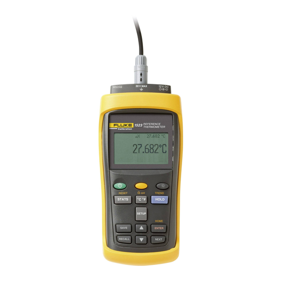
Reference thermometer
Hide thumbs
Also See for 1523:
- Technical manual (110 pages) ,
- User manual (36 pages) ,
- Technical manual (104 pages)

Related Manuals for Fluke 1523


Summary of Contents for Fluke 1523
- Page 1 1523, 1524 Reference Thermometer Technical Guide Revision 991701 MyFlukeStore 1.877.766.5412 www. .com Shop for Fluke products online at:...
- Page 2 Limited Warranty & Limitation of Liability Each product from Fluke Corporation, Hart Scientific Division (“Hart”) is warranted to be free from defects in material and workmanship under normal use and service. The warranty period is one year(s) for the Reference Thermometer. The warranty period begins on the date of the shipment.
-
Page 3: Table Of Contents
TC External Reference Junction ..............25 Probe Lock Function ................25 INFO-CON Connector ................26 Display Functions and User Interface ........29 Main Screen .................... 29 STATS ...................... 29 °C °F ....................... 29 MyFlukeStore 1.877.766.5412 www. .com Shop for Fluke products online at:... - Page 4 4.11 SHIFT ...................... 36 4.12 RESET ..................... 36 4.13 Ω mV ....................... 36 4.14 TREND ....................36 4.15 LOG ......................37 4.15.1 Free .......................37 4.15.2 Interval ......................37 4.15.3 Tag .........................38 MyFlukeStore 1.877.766.5412 www. .com Shop for Fluke products online at:...
- Page 5 Alignment Test Data ..................... 80 7.7.3.2 Calculate New Adjustment Values ............... 80 7.7.4 As Left Data ....................80 Preparation for Reference Thermometer Calibration ......80 7.8.1 Serial Communication ...................80 7.8.2 Cabling ......................81 MyFlukeStore 1.877.766.5412 www. .com Shop for Fluke products online at:...
- Page 6 AC Adapter ....................81 Manual Calibration Process ..............81 7.9.1 Procedure ......................82 7.9.1.1 Visual Inspection ....................82 7.9.1.2 1523/24 Calibration Parameters (As Found) ............82 7.9.1.3 1523/24 Accuracy Test (As Found) ..............84 7.9.2 1523/24 Alignment ..................89 7.9.2.1 L75_OHMS Range ....................92 7.9.2.2...
- Page 7 Figures Figure 1 Locking out non SI units ..............4 Figure 2 Clamp-On Ferrite ................. 5 Figure 3 Input/Output Connections - 1523 ............7 Figure 4 Input/Output Connections - 1524 ............8 Figure 5 Keys ..................... 9 Figure 6 1523 Menu ..................11 Figure 7 1523 Menu (cont) ................
- Page 8 Table 27 Standard Voltage Reference Specification ........78 Table 28 1523/24 Accuracy Test Settings and Specifications ......81 Table 29 1523/24 Accuracy Test Settings and Specifications – Voltage ..82 Table 30 As Found Readout/Calibration Parameter Settings ......82 Table 31 1523/24 Alignment Settings .............. 89...
-
Page 9: Before You Start
1 Before You Start 1.1 Introduction The Reference Thermometers (1523, 1524) are designed to be reliable, stable, tem- perature measuring instruments that can be used in the field or laboratory. They offer accuracy, portability, and speed for nearly every field calibration application. The... -
Page 10: Cautions
DO NOT operate this instrument in an excessively wet, oily, dusty, or dirty ● environment. Use the proper probes, function and range for your measurement. ● Ensure probe coefficients are downloaded. ● MyFlukeStore 1.877.766.5412 www. .com Shop for Fluke products online at:... -
Page 11: Ce Comments
RS-232 cables. 1.4.2 Immunity Testing 1.4.2.1 For Use As a Portable (Hand-held) Instrument The instrument was tested to Basic Immunity Requirements for portable test and mea- surement equipment. MyFlukeStore 1.877.766.5412 www. .com Shop for Fluke products online at:... -
Page 12: For Use As A Benchtop Instrument (Ac Adapter)
To attach a ferrite to a probe cable, make a loop in the cable near the connector and clamp the ferrite around half of the loop as shown in the diagram. The ferrite can be MyFlukeStore 1.877.766.5412 www. .com Shop for Fluke products online at:... -
Page 13: Emissions Testing
1.6 Emissions Testing The instrument fulfills the limit requirements for Class B. 1.7 Low Voltage Directive (Safety) In order to comply with the European Low Voltage Directive (2006/95/EC), Fluke equipment has been designed to meet the EN 61010-1. 1.8 Authorized Service Centers... -
Page 14: Quick Start
Quick Start Setup 2 Quick Start 2.1 Setup V DC V MAX Figure 3 Input/Output Connections - 1523 Table 2 1523 Input/Output Connections CALIBRATION 1523 THERMOMETER Name Description READOUT Serial Serial interface connector Connector, T1 Sensor Connector, Channel 1 Power... -
Page 15: Figure 4 Input/Output Connections - 1524
Serial interface connector Connector, T1 Sensor Connector, Channel 1 Connector, T2 Sensor Connector, Channel 2 Power External Power adapter connection TREND RESET ° ° STATS HOLD SETUP HOME ENTER SAVE MyFlukeStore 1.877.766.5412 www. .com Shop for Fluke products online at: NEXT RECALL... -
Page 16: Figure 5 Keys
Quick Start Setup V MAX V DC CALIBRATION 1524 THERMOMETER READOUT RESET TREND ° ° STATS HOLD SETUP HOME ENTER SAVE NEXT RECALL Figure 5 Keys MyFlukeStore 1.877.766.5412 www. .com Shop for Fluke products online at:... -
Page 17: Table 4 1523 Key Functions
1523, 1524 Reference Thermometer Setup Table 4 1523 Key Functions Description Power on or off Yellow Second or Special Function Key Turns the backlight on or off STATS 1st Press: MAX, 2nd Press: MIn, 3rd Press: AVE, 4th Press: STD DEV °... -
Page 18: Figure 6 1523 Menu
Quick Start Setup Figure 6 1523 Menu Figure 7 1523 Menu (cont) MyFlukeStore 1.877.766.5412 www. .com Shop for Fluke products online at:... -
Page 19: Figure 8 1523 Menu (Cont)
Figure 8 1523 Menu (cont) Table 5 1524 Key Functions Description Power on or off Yellow Second or Special Function Key Turns the backlight on or off STATS 1st Press: Max, 2nd Press: Min, 3rd Press: Ave, 4th Press: STD DEV °... - Page 20 “Ω mV” - Toggles from °C to Ω or Ω to °C (PRT, thermistor), °C to mV or mV to °C (TC) HOLD “TREND” - Starts Graphing data SAVE “LOG” - Log a series of measurements, see Auto Log in menu structure ENTER “HOME” Returns user to main screen MyFlukeStore 1.877.766.5412 www. .com Shop for Fluke products online at:...
-
Page 21: Figure 9 1524 Menu
1523, 1524 Reference Thermometer Setup Figure 9 1524 Menu Figure 10 1524 Menu (cont) MyFlukeStore 1.877.766.5412 www. .com Shop for Fluke products online at:... -
Page 22: Figure 11 1524 Menu (Cont)
Quick Start Setup Figure 11 1524 Menu (cont) MyFlukeStore 1.877.766.5412 www. .com Shop for Fluke products online at:... -
Page 23: Figure 12 1524 Menu (Cont)
1523, 1524 Reference Thermometer Setup Figure 12 1524 Menu (cont) MyFlukeStore 1.877.766.5412 www. .com Shop for Fluke products online at:... -
Page 24: Specifications
2.2 Specifications Specifications are based on a one year calibration cycle and apply from 13 °C to 33 °C unless stated otherwise. All specifications assume a five minute warm up period MyFlukeStore 1.877.766.5412 www. .com Shop for Fluke products online at:... -
Page 25: Table 6 General Specifications
0 Ω to 400 Ω ± (0.004 % + 0.002 Ω) Temperature Coefficient ( –10 °C to 13 °C, +33 °C to 60 °C): 0.0008 %/°C + 0.0004 Ω Excitation Current: 1 mA MyFlukeStore 1.877.766.5412 www. .com Shop for Fluke products online at:... -
Page 26: Table 10 Ohms Measurement, Thermistor
0 °C to 400 °C 0.25 °C –200 °C to 0 °C 0.54 °C 0 °C to 400 °C 0.24 °C Resolution: 0.01 ° Note 1: Accuracies are based on internal Reference Junction Compensation.. MyFlukeStore 1.877.766.5412 www. .com Shop for Fluke products online at:... -
Page 27: Table 12 Temperature, Thermocouples External Reference Junction
0 to 400 °C 0.13 °C -200 to 0 °C 0.27 °C 0 to 400 °C 0.13 °C Resolution: 0.01 °C Note 1: Accuracies are based on external reference junction compensation. MyFlukeStore 1.877.766.5412 www. .com Shop for Fluke products online at:... -
Page 28: Table 13 Temperature, Rtd Ranges
Probe combination for two Probe Type Channel 1 and 2 Channel 1 and 2 channel 1.3s 0.45s 0.9s PRT and PRT Thermistor 0.3s 0.6s Thermistor and Thermistor Thermocouple 0.3s 0.6s Thermocouple and Thermistor MyFlukeStore 1.877.766.5412 www. .com Shop for Fluke products online at:... -
Page 29: Table 17 Channel To Channel Differential Specifications
T1 – T2 Fast Scan Mode See Table “Fast Scan Mode Specifications” NOTE: Specification is for T1 – T2 < +/- 10 °C. For Like Probes only. Accuracies do not include probe accuracies. MyFlukeStore 1.877.766.5412 www. .com Shop for Fluke products online at:... -
Page 30: General Operation
The DC power source provides power to the 1523/24 reference thermometer. The AC adapter provided with the 1523/24 is intended to be used for this purpose. Use only the AC adapter supplied with the instrument. The DC power source plugs into the DC power input on the right side of the 1523/24. -
Page 31: Probe
AC adapter 3.3 Probe The probe is used to sense temperature. The 1523 is a single channel instrument and can measure using one probe. The 1524 is a dual channel instrument and can measure using two probes simultaneously. The probes attach to the 1523/24 using a Hart INFO- CON probe connector that plugs into the top of the instrument. -
Page 32: Internal Or External Reference Junction Compensation May Be Used With This Instrument
In this method, the reference junction is created externally and copper wires connect the reference junction to the 1523/24. The reference junction is placed in an ice bath or other temperature source that has a precisely known and stable temperature. This technique offers improved accuracy but is less convenient because of the more compli- cated connection scheme and the requirement of a precision temperature source. -
Page 33: Info-Con Connector
Communication Interface section of this manual 3.5 INFO-CON Connector The probe(s) connects to the top of the 1523/24 reference thermometer using a Hart INFO-CON connector. The probe connector will fit snugly and lock into place when it is fully inserted. The connector includes a memory device that stores the unique char- acteristics of the probe, allowing the instrument to measure temperature accurately. -
Page 34: Figure 16 Probe Wiring Diagrams
General Operation INFO-CON Connector Figure 16 Probe wiring diagrams MyFlukeStore 1.877.766.5412 www. .com Shop for Fluke products online at:... - Page 35 MyFlukeStore 1.877.766.5412 www. .com Shop for Fluke products online at:...
-
Page 36: Display Functions And User Interface
Units are displayed and recorded with temperature read- ings, auxiliary readings, and logged data. 4.4 HOLD This mode is identified by “HOLD” which appears on the bottom center of the display. MyFlukeStore 1.877.766.5412 www. .com Shop for Fluke products online at:... -
Page 37: Setup
This mode is identified by “W” along the top of the screen. In this mode, the resistance in Ohms for the temperature measurement appears on the top of the display. This op- tion is available when the selected channel is reading PRTs or thermistors. MyFlukeStore 1.877.766.5412 www. .com Shop for Fluke products online at:... -
Page 38: Temp Res
Channel T2 (1524 Only) Select the Channel T2 submenu by pressing the ENTER key. This menu allows the user access to view the probe data from the INFO-CON connector and to setup the MyFlukeStore 1.877.766.5412 www. .com Shop for Fluke products online at:... -
Page 39: Probe
This mode is identified by “DX” along the top of the screen. In this mode, the dif- ference (or delta) between the measurement and a previously stored reference value (Base X) appears on the top of the display. MyFlukeStore 1.877.766.5412 www. .com Shop for Fluke products online at:... -
Page 40: Temp Res
PC is not required. Data may be gathered in the Demand Log or Auto-Log modes prior to turning on the serial port and uploading the information. MyFlukeStore 1.877.766.5412 www. .com Shop for Fluke products online at:... -
Page 41: Baud Rate
The up and down arrow keys allow the user to select options within a field indicated by an up and down arrow indicator to the right or left of the field. MyFlukeStore 1.877.766.5412 www. .com Shop for Fluke products online at:... -
Page 42: Enter
4.9 RECALL The 1523/24 has a Demand Log that stores up to 25 readings that may be displayed on screen or sent out the serial port to a computer. The RECALL menu allows the user to review, delete, or send demand log data out the serial port. -
Page 43: Delete Logs
The temperature scale is displayed on the vertical axis and is adjustable up to 4 orders of magnitude. The display range is shown on the left side of the vertical axis and is ad- MyFlukeStore 1.877.766.5412 www. .com Shop for Fluke products online at:... -
Page 44: Log
The available range selections are +/- 0.01, +/-0.1, +/-1.0, +/- 10.0 °C. The vertical scale center is calculated automatically and displayed. The graphing function may be used on models 1523 and 1524. The 1523 will al- ways display Channel T1. When using the 1524 instrument, Channel T1 is selected by default, the user may select between Channel T1 and Channel T2 by pressing the “NEXT”... -
Page 45: Tag
This feature is used to start or stop logging sessions. Only the available condition (START or STOP) can be selected. 4.16 HOME The HOME key (SHIFT + ENTER) allows the user to return to the main screen from anywhere in the menu. MyFlukeStore 1.877.766.5412 www. .com Shop for Fluke products online at:... -
Page 46: Logs
There are two log features associated with models 1523/1524, the Demand Log and the Auto-Log. Both the 1523 and 1524 have a demand log that stores up to 25 read- ings. The 1524 has an Auto-Log that can store up to 15,000 readings at specified inter- vals. - Page 47 When the log storage is full, the lower line on the main screen will change to “LOG Full” and will remain until the user turns off the logging session by pressing the LOG key (SHIFT + SAVE) and pressing ENTER to stop the session. MyFlukeStore 1.877.766.5412 www. .com Shop for Fluke products online at:...
-
Page 48: Sending Auto Log Data To A Computer
RECALL or HOME (SHIFT + ENTER) key(s) at any time. This feature is available in model 1524 only. MyFlukeStore 1.877.766.5412 www. .com Shop for Fluke products online at:... - Page 49 MyFlukeStore 1.877.766.5412 www. .com Shop for Fluke products online at:...
-
Page 50: Digital Communication Interface
The following are examples of precautions that may be taken: 1. Use the 1523/24 demand log and auto log functions to avoid connecting to a computer when using grounded junction or bare junction thermocouples. Once the readings are complete, connect the RS-232 cable and upload the data to the personal computer. -
Page 51: Setup
(CR) and a new line (LF) command. 6.2 Command Syntax The instrument accepts commands for setting parameters, executing functions or responding with requested data. These commands are in the form of strings of ASCII- MyFlukeStore 1.877.766.5412 www. .com Shop for Fluke products online at:... -
Page 52: Serial Commands By Function Or Group
If a command with a value of 2 is used on a 1523, which has only one probe, a command error occurs and the command is ignored. 6.3 Serial Commands by Function or Group In this section, the commands are arranged into the following groups: Data Logging Commands –... -
Page 53: Table 18 Commands By Function Or Group
Cal<chn>:DEV:LOCK <bool> Conditional* (none) CAL<chn>:DEV:LOCK:DATA? (none) CAL<chn>:DEV:RANG:ADJ<num>? (none) CAL<chn>:DEV:RANG:ADJ<num> <val> Conditional* (none) CAL<chn>:DEV:RANG:CLEA Conditional* (none) CAL<chn>:DEV:RANG:NUM (none) CAL<chn>:DEV:RANG:NUM <val> Conditional* (none) CAL<chn>:DEV:RANG:REF<num>? (none) CAL<chn>:DEV:RANG:REF<num> <val> Conditional* (none) CAL<chn>:DEV:RANG:SEL? (none) CAL<chn>:DEV:RANG:SEL <val> MyFlukeStore 1.877.766.5412 www. .com Shop for Fluke products online at:... - Page 54 Conditional* (none) CALC<prb>:CONV:VERS? (none) CALC<prb>:CONV:VERS <num> Conditional* Status & Event (none) *RST (none) STAT:MEAS:EVEN? (none) STAT:MEAS:COND? (none) STAT:MEAS:ENAB? (none) STAT:MEAS:ENAB <num> (none) STAT:QUES:EVEN? (none) STAT:QUES:COND? (none) STAT:QUES:ENAB? (none) STAT:QUES:ENAB <num> MyFlukeStore 1.877.766.5412 www. .com Shop for Fluke products online at:...
-
Page 55: Serial Commands - Alphabetic Listing
Lower case letters are optional and may be omitted. < > indicates a required parameter. ● [ ] indicates optional parameters. ● ( ) indicates a group of parameters that must be used together. ● MyFlukeStore 1.877.766.5412 www. .com Shop for Fluke products online at:... - Page 56 Clear the event registers and the error queue. Example: *CLS This command has no response. *IDN? Returns the instrument identification string that indicates the manufacturer, model number, serial number, and firmware version. MyFlukeStore 1.877.766.5412 www. .com Shop for Fluke products online at:...
- Page 57 Set the last calibration date for the specified probe. The CALCulate suffix, <prb>, specifies the probe, 1 or 2. Defaults to 1 if omitted. The <year> parameter is a four-digit number, 2000 to 2099. MyFlukeStore 1.877.766.5412 www. .com Shop for Fluke products online at:...
- Page 58 If there are no parameters available for the current conversion type, an empty string is returned. The list of parameters depends on the selected conversion type as listed in Table 21 on page 74. MyFlukeStore 1.877.766.5412 www. .com Shop for Fluke products online at:...
- Page 59 Example: CALC2:CONV:SNUM? Response: A_336C CALCulate<prb>:CONVert:SNUMber <seri> Set the probe serial number for the specified probe. The CALCulate suffix, <prb>, specifies the probe, 1 or 2. Defaults to 1 if omitted. MyFlukeStore 1.877.766.5412 www. .com Shop for Fluke products online at:...
- Page 60 Example: CALC2:CONV:IDEN 23 NOTE: This command is protected, which requires a password to set it. Error ‘-2003, “Command protected”’ is queued if the password has not been entered with SYST:PASS:CEN MyFlukeStore 1.877.766.5412 www. .com Shop for Fluke products online at:...
- Page 61 If a probe is inserted, the response is 0 if both the channel and the probe are not locked; otherwise 1 if either is locked. The CALibrate<chn>:DEVice:LOCK:DATA query may be used to obtain details of the channel and probe locks. MyFlukeStore 1.877.766.5412 www. .com Shop for Fluke products online at:...
- Page 62 The ADJust suffix, <num>, specifies the calibration point, 1 to the number set with the associated command CAL:DEV:RANG:NUM. If omitted, offset values for all points are returned, separated by commas. The range must have been preselected with the command CAL<chn>:DEV:RANG:SEL. MyFlukeStore 1.877.766.5412 www. .com Shop for Fluke products online at:...
- Page 63 Return the number of calibration points for the preselected range. The range must have been preselected with the command CAL<chn>:DEV:RANG:SEL. The response is the number of calibration points in use. MyFlukeStore 1.877.766.5412 www. .com Shop for Fluke products online at:...
- Page 64 The reference points, 1 to the specified number, must be entered in ascending order. Example: CAL:DEV:RANG:REF2 10.568 NOTE: This command is protected, which requires a password to set it. MyFlukeStore 1.877.766.5412 www. .com Shop for Fluke products online at:...
- Page 65 The DISPlay suffix, <chn>, specifies the channel, 1 or 2. Defaults to 1 if omitted. Example: DISP1:RES? Response: 2 DISPlay<chn>:RESolution <num> Set the maximum display resolution for the channel. The DISPlay suffix, <chn>, specifies the channel, 1 or 2. Defaults to 1 if omitted. MyFlukeStore 1.877.766.5412 www. .com Shop for Fluke products online at:...
- Page 66 Return the tag number to which the LOG:AUT:POIN, LOG:AUT:STAT, and LOG:AUT:VAL commands presently apply. Return a value of 1 to 25, or 0 if not set. Error ‘-221,”Settings conflict”’ is queued if the data logging storage is corrupt. MyFlukeStore 1.877.766.5412 www. .com Shop for Fluke products online at:...
- Page 67 When only one channel is active, no records are sent for the inactive channel. Error ‘-221,”Settings conflict”’ is queued if the data logging storage is corrupt. MyFlukeStore 1.877.766.5412 www. .com Shop for Fluke products online at:...
- Page 68 LOG:AUT:LAB, or if the LOG or any recall menu display is active. Example: LOG:AUT:STAT 0 LOGging:AUTomatic:TIMe? Return the Auto-Log interval. Returns AUTO, 1, 2, 5, 10, 30, or 60. Numeric intervals are expressed in seconds. MyFlukeStore 1.877.766.5412 www. .com Shop for Fluke products online at:...
- Page 69 Delete all entries from the demand log. Error ‘-221,”Settings conflict”’ is queued if the data logging storage is corrupt, or if the demand recall or demand delete display is active. MyFlukeStore 1.877.766.5412 www. .com Shop for Fluke products online at:...
- Page 70 Send all demand log entries. This example shows the 1524 return data. A single channel, and no time and date, are shown on the 1523 return data. Each data line includes the default or user defined demand log description, the channel number, the primary value and units, and on the 1524 the time and date.
- Page 71 The example shows the 1524 return data. A single channel, and no time and date, are shown on the 1523 return data. Each data line includes the default or user defined demand log description, the channel number, the primary value and units, and on the 1524 the time and date.
- Page 72 Serial Commands - Alphabetic Listing The example shows the 1524 return data. A single channel, and no time and date, are shown on the 1523 return data. Each data line includes the default or user defined demand log description, the channel number, the requested value and units, and on the 1524 the time and date.
- Page 73 If there is no valid measurement available the response is “0.0,OL”. If the presently selected input type is millivolts, there will be no response and error ‘-221,"Settings conflict"’ will be queued. MyFlukeStore 1.877.766.5412 www. .com Shop for Fluke products online at:...
- Page 74 The parameter <val> is expressed in degrees Celsius, and may range from -10C to 60C. Example: SENS:RJ:TEMP 23.123 STATus:MEASure:EVENt? Read and clear the Measurement Event Register, indicating whether or not a new mea- surement is available to be read. MyFlukeStore 1.877.766.5412 www. .com Shop for Fluke products online at:...
- Page 75 1 not inserted bit 1: probe 1 measurement under range bit 2: probe 1 measurement over range bit 3: probe 1 EEPROM fault (bad checksum or version number is not supported) MyFlukeStore 1.877.766.5412 www. .com Shop for Fluke products online at:...
- Page 76 The bit assignments are the same as for the STATus:QUEStionable?. Example: STAT:QUES:ENAB 1799 SYSTem:COMMunicate:SERial:BAUD? Return the present serial port baud rate setting. The response is the present baud rate setting. MyFlukeStore 1.877.766.5412 www. .com Shop for Fluke products online at:...
- Page 77 The <day> parameter is a one or two-digit number. 1 to 31. This command is only available in the model 1524, and results in a command error if used with the model1523. MyFlukeStore 1.877.766.5412 www. .com Shop for Fluke products online at:...
- Page 78 The <pass> parameter is the new password. It can be up to 10 characters in length and can include any upper case letters, numeric digits, and the underscore (‘_’). The default password at time of shipping is 1234. MyFlukeStore 1.877.766.5412 www. .com Shop for Fluke products online at:...
- Page 79 The <second> parameter is a one or two-digit number 0 to 59. This command is only available in the model 1524, and results in a command error if used with the model1523. Example: SYST:TIME 18,43,23 SYSTem:VERSion? Return the SCPI version number. MyFlukeStore 1.877.766.5412 www. .com Shop for Fluke products online at:...
-
Page 80: Table 19 Statistical Types
Maximum Minimum Average Standard Deviation Delta X Delta T Table 20 Probe Conversion Types Probe Conversion Keyword ITS90 ITS90-5 ITS5 PT100 RPRT Resistance TRES Thermistor Polynominal R(T) TRES Resistance RTHM MyFlukeStore 1.877.766.5412 www. .com Shop for Fluke products online at:... -
Page 81: Table 21 Probe Characterization Parameters
Double Floating Point Double Floating Point MINOP Integer, °C MAXOP Integer, °C Double Floating Point Double Floating Point Double Floating Point Double Floating Point MINOP Integer, °C MAXOP Integer, °C MyFlukeStore 1.877.766.5412 www. .com Shop for Fluke products online at:... -
Page 82: Table 22 Calibration Range Identifiers
Table 22 Calibration Range Identifiers Range Keyword Normal operation NORMAL Millivolts calibration Reference junction calibration RJ_OHMS Very Low Ohms calibration L75_OHMS Low Ohms calibration LO_OHMS Medium Ohms calibration MED_OHMS High Ohms calibration HI_OHMS MyFlukeStore 1.877.766.5412 www. .com Shop for Fluke products online at:... -
Page 83: Table 23 Demand Log Statistical Types
Table 24 Error Messages Number Message "No error" -100 "Command error" -200 "Execution error" -203 "Command protected" -221 “Settings conflict” -350 "Queue overflow" -360 "Communication error" -363 "Input buffer overrun" MyFlukeStore 1.877.766.5412 www. .com Shop for Fluke products online at:... -
Page 84: Calibration Of Your Reference Thermometer Readout
NOTE: The Unit Under Test is referred to as the (UUT). 7.4 Fundamentals It is assumed that the user is familiar with the 1523/24 Reference Thermometer User’s Guide and Technical Guide. The user shall be familiar with 4 wire and 2 wire resistance connections. -
Page 85: Manual Calibration
Thermometer was calibrated at the factory. The user should adjust their calibration process to meet the needs of their facility and process. The following flow charts sum- marizes the process. MyFlukeStore 1.877.766.5412 www. .com Shop for Fluke products online at:... -
Page 86: Figure 18 Flow Chart For Manual Calibration
Parameters Set Reference As-Found Test Points and Reset Data Adj Values Take Alignment Data Calculate New Adj Values As Left Accuracy Data Finished Figure 18 Flow chart for manual calibration MyFlukeStore 1.877.766.5412 www. .com Shop for Fluke products online at:... -
Page 87: As Found Data Procedure
Select Instrument then press ENTER. Press NEXT until the parameter Serial Port is shown. Toggle the up / down keys to select On and press ENTER. Press SETUP or HOME to return to the main screen. MyFlukeStore 1.877.766.5412 www. .com Shop for Fluke products online at:... -
Page 88: Cabling
7.9 Manual Calibration Process NOTE: 1. The 1523/24 is tested and calibrated using the tests outlined below in the order indicated. Details on performing each of the tests can be found in the subsequent section of this document. -
Page 89: Table 29 1523/24 Accuracy Test Settings And Specifications - Voltage
7.9.1.2 1523/24 Calibration Parameters (As Found) NOTE: If not taking As Found data, skip to the 1523/24 alignment section. When the calibration process must collect As Found data, the following UUT configu- ration and control settings must remain at their current values until all As Found data has been collected. - Page 90 CAL1:DEV:RANG:SEL HI_OHMS 13. Query the Ref points by sending the following Command: CAL1:DEV:RANG:REF? 14. Query the ADJ values for the range by sending the following Command: CAL1:DEV:RANG:ADJ? MyFlukeStore 1.877.766.5412 www. .com Shop for Fluke products online at:...
-
Page 91: Accuracy Test (As Found)
The ADJ values will be in order of the ref points queried in the previous step. 18. Record the as found alignment parameters. 7.9.1.3 1523/24 Accuracy Test (As Found) 19. Connect the calibration cable, described in the Preparation and Settings for Reference readout Calibration section, to Channel T1 of the UUT. Using a... - Page 92 MEAS? Record the data. Note: Steps 38 through 42 apply to the 1524 only. Proceed to step 43 if using a 1523. 38. (1524 ONLY) Set Channel T2 of the UUT in the LO_OHMS cal range by sending the following commands through the serial port:...
- Page 93 51. Query the reading every 2 seconds for 40 readings using the following command: MEAS? Record the data. Note: Steps 52 through 56 apply to the 1524 only. Proceed to step 57 if using a 1523. MyFlukeStore 1.877.766.5412 www. .com...
- Page 94 Record the data. 64. Connect a 500K Ohm resistor to the calibration cable connected to the UUT. 65. Query the reading every 2 seconds for 40 readings using the following command: MEAS? MyFlukeStore 1.877.766.5412 www. .com Shop for Fluke products online at:...
- Page 95 Manual Calibration Process Record the data. Note: Steps 66 through 70 apply to the 1524 only. Proceed to step 71 if using a 1523. 66. (1524 ONLY) Set Channel T2 of the UUT in the HI_OHMS cal range by sending the following commands through the serial port: CAL2:DEV:RANG:SEL HI_OHMS 67.
-
Page 96: Table 31 1523/24 Alignment Settings
1523/24 Alignment Prior to performing the alignment, the following UUT configuration and control set- tings must be set to the values indicated in the 1523/24 Alignment Settings table. Caution: Failure to do this will cause large errors in the measurement readings and invalidate the calibration. - Page 97 CAL:DEV:RANG:SEL HI_OHMS CAL:DEV:RANG:NUM 2 CAL:DEV:RANG:SEL MV CAL:DEV:RANG:NUM 2 3. Set all Reference points to their designated values (see Table 31 on previous page, 1523/24 Alignment settings) for each range by sending the following commands: CAL:DEV:RANG:SEL L75_OHMS CAL:DEV:RANGE:REF1 0.0 CAL:DEV:RANGE:REF2 75.0 MyFlukeStore 1.877.766.5412...
- Page 98 X represents which ADJ value for that range, 1 or 2 Average is the average of the 40 measured samples at one reference point. Nominal is the exact known value of the reference resistor or voltage source. MyFlukeStore 1.877.766.5412 www. .com Shop for Fluke products online at:...
-
Page 99: L75_Ohms Range
The XXXX represents the new calculated value. CAL:DEV:RANG:SEL L75_OHMS CAL:DEV:RANGE:ADJ1 XXXX CAL:DEV:RANGE:ADJ2 XXXX CAL:DEV:RANG:SEL LO_OHMS CAL:DEV:RANGE:ADJ1 XXXX CAL:DEV:RANGE:ADJ2 XXXX CAL:DEV:RANG:SEL MED_OHMS CAL:DEV:RANGE:ADJ1 XXXX CAL:DEV:RANGE:ADJ2 XXXX CAL:DEV:RANG:SEL HI_OHMS CAL:DEV:RANGE:ADJ1 XXXX CAL:DEV:RANGE:ADJ2 XXXX MyFlukeStore 1.877.766.5412 www. .com Shop for Fluke products online at:... -
Page 100: As Left Test Data
CAL:DEV:RANGE:ADJ1 XXXX CAL:DEV:RANGE:ADJ2 XXXX 7.9.3 1523/24 As Left Test Data 1. Take as Left data by following the steps in the As Found Data section. 2. Calculate the average and the standard deviation of the measurements taken in step 1, including the Channel T2 data. Record the results. -
Page 101: Troubleshooting
Electrical interference. Intense radio frequency radiation near the thermometer or the probe can induce noise into the measurement circuits resulting in erratic readings. Try eliminating the source of interference or moving the thermometer to a different location. MyFlukeStore 1.877.766.5412 www. .com Shop for Fluke products online at:... - Page 102 Before using any cleaning or decontamination method except those recommended by Fluke, users should check with an Authorized Service Center to ensure that the pro- posed method will not damage the equipment. If the AC adapter becomes damaged, have it replaced immediately. Never disassemble the AC adapter or attempt to repair it.
- Page 103 Calibration and Setup Commands 45 CALCulate:AVERage:CLEar 50 Calibration Equipment 77 CALCulate:AVERage<n>:TYPE? 50 Calibration Parameters 82 CALCulate<prb>:AVERage<n>:DATA? 50 Calibration Process 81 CALCulate<prb>:CONVert:DATE:CALibrate? Calibration Range Identifiers 75 Channel T1 Setup 30 Channel T2 Setup 30 MyFlukeStore 1.877.766.5412 www. .com Shop for Fluke products online at:...
-
Page 104: Maintenance
Probe 24 INFO-CON 24, 26 Probe Lock 25 Interval 37 Probe parameters 45 Probe Setup Commands 45 Probe wiring diagrams 27 L75 Ohms Range 84 PRTs 24 L75_OHMS Range 92 MyFlukeStore 1.877.766.5412 www. .com Shop for Fluke products online at:... - Page 105 STATus:MEASure:ENABle <num> 68 STATus:MEASure:EVENt? 67 STATus:QUEStionable:CONDition? 69 STATus:QUEStionable:ENABle 69 STATus:QUEStionable:ENABle <num 69 STATus:QUEStionable:EVENt? 68 Syntax, Command 44 System Commands 45 SYSTem:COMMunicate:SERial:BAUD? 69 SYSTem:COMMunicate:SERial:BAUD <baud> SYSTem:COMMunicate:SERial:OFF 70 SYSTem:DATE? 70 SYSTem:DATE <year>,<month>,<day> 70 MyFlukeStore 1.877.766.5412 www. .com Shop for Fluke products online at:...
Need help?
Do you have a question about the 1523 and is the answer not in the manual?
Questions and answers