Table of Contents
Advertisement
Quick Links
Advertisement
Table of Contents

Related Manuals for Fluke Hart Scientific 1575 Super-Thermometer


Summary of Contents for Fluke Hart Scientific 1575 Super-Thermometer
- Page 1 Hart Scientific 1575/1590 Thermometer Readout User’s Guide Rev. 5B2802...
- Page 2 Fluke Corporation, Hart Scientific Division 799 E. Utah Valley Drive • American Fork, UT 84003-9775 • USA Phone: +1.801.763.1600 • Telefax: +1.801.763.1010 E-mail: support@hartscientific.com www.hartscientific.com Subject to change without notice. • Copyright © 2005 • Printed in USA Rev. 5B2802...
-
Page 3: Table Of Contents
Table of Contents 1 Before You Start ......1 Symbols Used ......1 Safety Information . - Page 4 Front Panel Display ......24 Front Panel Buttons ......25 6 General Operation .
- Page 5 7.4.4.2.6 Setup ..........59 7.4.4.2.7 Measure .
- Page 6 8.2.1 Setup ........101 8.2.2 IEEE-488 Interface Functions .
- Page 7 11.5.1.2 Scanner Sequence ........130 11.5.2 Probe Menu .
- Page 8 Figures Figure 1 Simplified Schematic Diagram of the Measurement Circuit ..6 Figure 2 Measurement Processing Operations ....7 Figure 3 1575/1590 Super-Thermometer Display .
- Page 9 Tables Table1 International Electrical Symbols ..... 1 Table 2 ITS-90 Subranges and Coefficients ....48 Table 3 DIN-43760/IEC-751/ASTM E1137 Callendar-Van Dusen Coefficients.
-
Page 11: Before You Start
1 Before You Start Symbols Used Before You Start Symbols Used Table 1 lists the symbols that may be used on the instrument or in this manual and the meaning of each symbol. Table1 International Electrical Symbols Symbol Description AC (Alternating Current) AC-DC Battery Complies with European Union Directives... -
Page 12: Safety Information
1575/1590 Thermometer Readout User’s Guide Symbol Description Canadian Standards Association OVERVOLTAGE (Installation) CATEGORY II, Pollution Degree 2 per IEC1010-1 re- fers to the level of Impulse Withstand Voltage protection provided. Equipment of OVERVOLTAGE CATEGORY II is energy-consuming equipment to be supplied from the fixed installation. -
Page 13: Cautions
• Keep the probe wires clean and away from fluids. Authorized Service Centers Please contact one of the following authorized Service Centers to coordinate service on your Hart product: Fluke Corporation, Hart Scientific Division 799 E. Utah Valley Drive American Fork, UT 84003-9775 Phone: +1.801.763.1600 Telefax: +1.801.763.1010... - Page 14 22 Jianguomenwai Dajie Chao Yang District Beijing 100004, PRC CHINA Phone: +86-10-6-512-3436 Telefax: +86-10-6-512-3437 E-mail: xingye.han@fluke.com.cn Fluke South East Asia Pte Ltd. Fluke ASEAN Regional Office Service Center 60 Alexandra Terrace #03-16 The Comtech (Lobby D) 118502 SINGAPORE Phone: +65 6799-5588 Telefax: +65 6799-5588 E-mail: antng@singa.fluke.com...
-
Page 15: Introduction
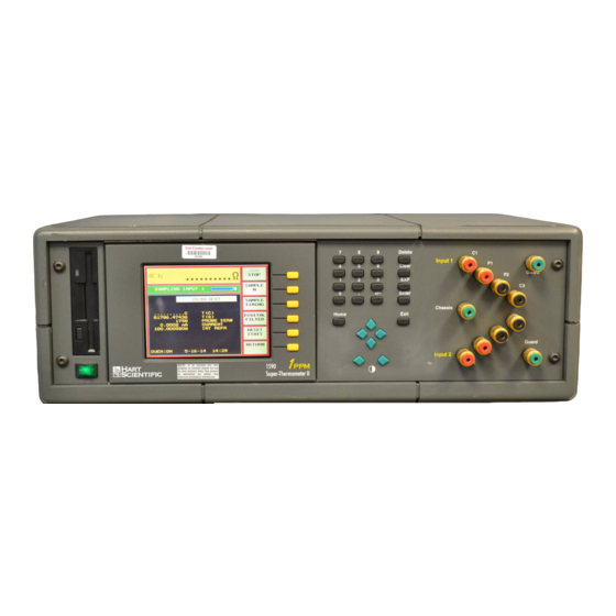
2 Introduction General Description Introduction General Description The 1575 “Super-Thermometer” and 1590 “Super-Thermometer II” are two of the most accurate resistance and temperature readout instruments available. The 1575 can deliver resistance measurements with up to 4 ppm accuracy while the 1590 can achieve 1 ppm accuracy. -
Page 16: Measurement Technique
1575/1590 Thermometer Readout User’s Guide technique used by these instruments and discusses issues related to performance. 2.2.1 Measurement Technique Fundamentally, the 1575/1590 measures the resistance ratio between two resis- tors by comparing their voltages when equal currents are applied. The simpli- fied schematic in Figure 1 shows the basic components of the measurement circuitry. -
Page 17: Performance Issues
2 Introduction Theory of Operation Using this approach, errors from driving current imprecision, voltage offsets, and amplifier and ADC inaccuracies are avoided because these all affect the voltage samples equally. Each voltage sample requires 0.5s. It takes 0.15s to set the current and relay and allow time for the voltages to settle and 0.35s for the ADC to make a mea- surement and send it to the CPU. -
Page 18: Lead Resistance
1575/1590 Thermometer Readout User’s Guide temperature measurements. It also offers other advantages that contribute to the value of this instrument. Consider the following issues. 2.2.2.1 Lead Resistance Measurements using an electrical sensor can be affected by the resistance in the connecting wires or leads. -
Page 19: Reactance
2 Introduction Theory of Operation 2.2.2.3 Reactance The use of AC driving current can cause errors in resistance thermometry be- cause sensors often exhibit significant inductance and capacitance. The 1575/1590 uses DC circuitry that is much less susceptible to these effects. It al- lows plenty of time for currents and voltages to settle before it begins a sample. -
Page 20: Nonlinearity
1575/1590 Thermometer Readout User’s Guide time. This makes it impossible to detect small real changes in the parameter be- ing measured. In effect, it limits the resolution of the measuring instrument. Electrical noise in the 1575/1590 comes from a variety of sources. A small amount of noise is generated by the resistors and semiconductor devices in the measurement circuitry. -
Page 21: Solid-State Design
2 Introduction Theory of Operation Compare this to a typical resistance bridge that takes 30 to 60 seconds to make the first measurement after a sensor is connected. The speed of the 1575/1590 gives it the advantage of allowing greater efficiency as well as better accuracy during a batch calibration process involving a large number of sensors. -
Page 23: Specifications And Environmental Conditions
3 Specifications and Environmental Conditions Specifications Specifications and Environmental Conditions Specifications Specification 1575 1590 Resistance Measurement Range 0 to 500 kΩ Resistance Ratio Accuracy 0 to .25Ω input (1Ω refr, 10 mA) 0.00001Ω 0.000005Ω 40 ppm 20 ppm 0.25 to 4Ω input (1Ω refr, 10 mA) 20 ppm 5 ppm 2.5 to 40Ω... - Page 24 1575/1590 Thermometer Readout User’s Guide Specification 1575 1590 100Ω SPRT (0°C, 100Ω refr, 1 mA) 0.002°C 0.0015°C 0.0005°C 0.00025°C 10 kΩ thermistor (25°C, 10 kΩ refr, 0.01 mA) Typical RMS Measurement Noise No Filter 20 Second Filter 25 ppm 8 ppm 0.25Ω...
-
Page 25: Environmental Conditions
• Altitude less than 2,000 meters Warranty Fluke Corporation, Hart Scientific Division (Hart) warrants this product to be free from defects in material and workmanship under normal use and service for a period as stated in our current product catalog from the date of shipment. -
Page 27: Quick Start
4 Quick Start Unpacking Quick Start This section briefly explains the basics of setting up and operating your 1575 or 1590 thermometer readout. Unpacking Carefully unpack the 1575 or 1590 thermometer readout and inspect it to make sure all components are present and in satisfactory condition. Verify that the following items are present: •... -
Page 28: Switch The Power On
1575/1590 Thermometer Readout User’s Guide There are also ‘Guard’ patented DWF connectors for each channel and a ‘Chas- sis’ patented DWF connector that can be used for attaching guard wires and for grounding. Probes that have shielded cables will be less susceptible to electro- magnetic interference (EMI). - Page 29 4 Quick Start Measure Temperature 4. Set the temperature conversion type. Move the cursor to the CON- VERSION selection. Use the L and R keys and Enter to select ITS-90 or whatever conversion is appropriate for your probe (Section 7.4.3.2). Refer to the calibration report or specifications for your probe. Most SPRTs and RTDs use the ITS-90.
-
Page 31: Parts And Controls
5 Parts and Controls Front Panel Parts and Controls This section describes the exterior features of the 1575/1590. Front Panel The following are found on the front of the 1575/1590. Display The display is a 320 x 240 pixel color graphics LCD device with a bright CCFT backlight. -
Page 32: Back Panel
1575/1590 Thermometer Readout User’s Guide Disk Drive The 3.5" floppy disk drive is located at the left side of the front panel. The disk drive can be used to store probe data and operating parameters and to log mea- surement data. The drive is MS-DOS compatible allowing data to be trans- ferred between the 1590 and PC-compatible computers. - Page 33 5 Parts and Controls Back Panel The fan is necessary to keep the internal components cool. Always make sure air can flow freely behind and around the instrument. Serial Connector The serial connector is a 9-pin subminiature D type located on the back panel. The serial (RS-232) interface can be used to transmit measurements and control the operation of the 1575/1590.
-
Page 34: Front Panel Display
1575/1590 Thermometer Readout User’s Guide Front Panel Display The front panel display is shown in detail in Figure 3 and its features are de- scribed below. Figure 3 1575/1590 Super-Thermometer Display The display is a 320 x 240 pixel graphics LCD device with a bright CCFT backlight. -
Page 35: Front Panel Buttons
5 Parts and Controls Front Panel Buttons Warning Messages From time-to-time important warning messages may appear immediately below the measurement. “FILTER RESET” indicates the filter has been reset (see Sec- tion 7.2.4). “WARNING: SUBRANGE EXCEEDED” indicates the measure- ment is outside the ITS-90 subrange (see Section 7.4.3.2.1). Sampling Status Below the measurement window is a box where the sampling status and mes- sages are displayed. - Page 36 1575/1590 Thermometer Readout User’s Guide Soft-keys The six soft-keys to the right of the display are used to select menus or menu functions. The functions of the soft-keys are indicated in the small boxes on the display just to the left of the soft-keys. The functions of the soft-keys change depending on the selected menu.
- Page 37 5 Parts and Controls Front Panel Buttons The up and down arrow keys are used to move the cursor through a list of pa- rameters in a window. Note that parameter entry will not be accepted if the up or down button was pressed before Enter. Thus these keys can also be used to intentionally cancel a change to a parameter.
-
Page 39: General Operation
6 General Operation Applications General Operation This section provides applications, suggestions for best results, and answers to some common questions concerning operating the 1575/1590 Super-Thermometer. Applications Listed here are some of the applications for which the 1575/1590 Thermometer is well suited. •... -
Page 40: Suggestions For Best Results
1575/1590 Thermometer Readout User’s Guide • Self-heating tests. The 1575/1590 offers very flexible control of the exci- tation current used in measuring sensors and resistors. The current can be finely adjusted to provide the optimum resolution and accuracy with mini- mum self-heating error (see Section 7.4.3.4). -
Page 41: Maintaining Accuracy
6 General Operation Suggestions for Best Results 6.2.1 Maintaining Accuracy There are many potential problems that can lead to inaccurate results when us- ing the 1575/1590. Some of these are: improper calibration of the 1575/1590, incorrect setup of the 1575/1590 parameters, wrong probe characterization co- efficients, a damaged probe or sensor, poor connection of the probe wires, or misuse of the 1575/1590. -
Page 42: Evaluating Temperature Uncertainty
1575/1590 Thermometer Readout User’s Guide SPRT to make sure it is accurate. One way to do this is to compare its measurements to those of a second SPRT. 7. Check system accuracy with a fixed-point cell. An excellent way to verify the accuracy of the entire system, including the 1575/1590, refer- ence resistors, and SPRT, is to check measurements using a fixed-point cell. -
Page 43: Answers To Some Common Questions
6 General Operation Answers to Some Common Questions tions and uniformity. Carefully consider all sources of uncertainty when evalu- ating total system uncertainty. Answers to Some Common Questions Following are answers to some often-asked questions. Can the 1575/1590 be used with thermocouples? No. - Page 44 1575/1590 Thermometer Readout User’s Guide If I only use the internal 100Ω reference resistor, do I need to maintain cali- bration of the other reference resistors? If you only use certain internal reference resistors it is not necessary to cali- brate the unused resistors.
- Page 45 6 General Operation Answers to Some Common Questions etc.). Fourth, select the probe for ITS-90 calibration using SETUP in CAL ITS-90 (Section 7.4.4.2.6). Fifth, enter the resistance and temperatures using DATA (Section 7.4.4.2.8). Sixth, calculate the ITS-90 coefficients using CAL- CULATE (Section 7.4.4.2.9).
-
Page 47: Front Panel Operation
7 Front Panel Operation Channel Menu Front Panel Operation This chapter explains operation of the 1575/1590 thermometer in detail using the front panel buttons and soft-keys. Aside from the display contrast adjust- ment which is controlled by dedicated buttons on the front panel, all instrument functions are controlled using the soft-key menu system. -
Page 48: Figure 4 Menu Tree
1575/1590 Thermometer Readout User’s Guide MAIN MENU CHANNEL MENU * INPUT 1 Select Input 1 for measurement INPUT 2 Select Input 2 for measurement ALT N Alternate between Input 1 and Input 2 SAMPLE MENU RUN/STOP Start or stop continuous sampling SAMPLE N Start sampling for N measurements SAMPLE TIMING... -
Page 49: Measure Input 2
7 Front Panel Operation Sample Menu 7.1.2 Measure Input 2 Press the INPUT 2 soft-key to select Input 2 for measurement. Measurements made with this channel will use the probe setup parameters specified for Input 7.1.3 Alternate Channels Press the ALT N soft-key to select the alternating measurement mode. With this mode the channels are automatically switched after a certain number of mea- surements are made on each. -
Page 50: Sampling Run/Stop
1575/1590 Thermometer Readout User’s Guide 7.2.1 Sampling Run/Stop The RUN/STOP soft-key is used to start and stop sampling. The soft-key label will indicate the present status by graying RUN or STOP. The run/stop sampling function overrides any of the or disk sampling functions (see Section 7.6.3 and 7.6.4). -
Page 51: Digital Filter
7 Front Panel Operation Sample Menu sary. Four seconds is recommended when measuring resistance above 100kΩ. To determine if there is error in the measurement due to inadequate delay, com- pare measurements using the normal conversion time with measurements using twice the normal conversion time. -
Page 52: Figure 7 Effect Of Automatic Reset On Filtered Measurements
1575/1590 Thermometer Readout User’s Guide measurements taken within the time specified by the response time. The expo- nential filter simulates a 1-pole analog filter where more recent measurements are given more weight than earlier measurements. The filter can also be dis- abled by selecting NONE. -
Page 53: Reset Statistics
7 Front Panel Operation Memory Menu ture during sudden large temperature changes. However, the threshold should not be too small or the reset may be triggered by ordinary noise making the fil- ter ineffective. The message “FILTER RESET” appears below the temperature display whenever the filter resets to help alert you if there is a problem. -
Page 54: Store Sample
1575/1590 Thermometer Readout User’s Guide The memory menu includes the soft-keys STORE SAMPLE, WRITE VALUE, VIEW MEMORY, CLEAR MEMORY, and RUN/PAUSE. 7.3.1 Store Sample The STORE SAMPLE soft-key places the most recent measurement in a mem- ory location you specify. Since the measurement may be updated while you are trying to store it in memory, you may first want to pause sampling temporarily using the RUN/PAUSE soft-key. -
Page 55: Clear Memory
7 Front Panel Operation Probe Menu tion and the next four. You can use the or scroll buttons to scroll the list. Press Exit when you are finished viewing. 7.3.4 Clear Memory The CLEAR MEMORY soft-key clears the contents of memory, setting all the values to 0.0°C. -
Page 56: Select Channel
1575/1590 Thermometer Readout User’s Guide The probe menu includes INP 1/INP 2, SELECT PROBE, EDIT PROBE, CAL PROBE, and PROBE DISK soft-keys. If the 2590 Scanner is connected to the 1575/1590, the first soft-key will appear as SELECT CHAN instead. To change the probe definition for a particular channel, first use INP 1/INP 2 to select the channel to edit then use SELECT PROBE to assign a different probe number or EDIT PROBE to change the parameters. -
Page 57: Serial Number
7 Front Panel Operation Probe Menu • Standby current (1590 with 2590 only) • Three-wire offset • Sub-range (ITS-90 only) • Characterization coefficients applicable to conversion type and selected subrange 7.4.3.1 Serial Number For SERIAL NO. you can enter up to ten characters that consist of digits from 0 to 9, upper case letters from “A”... -
Page 58: Ipts-68
1575/1590 Thermometer Readout User’s Guide Table 2 shows the various ITS-90 subranges with the temperature range and co- efficients. All subranges also include R(TPW) (the resistance at 273.16K) as a coefficient. For details about the ITS-90 see NIST Technical Note 1265, Guide- lines for Realizing the International Temperature Scale of 1990. -
Page 59: Polynomial
7 Front Panel Operation Probe Menu ⎧ ⎧ ⎫ ⎡ ⎤ ⎛ ⎞ α − δ − ≥ ⎜ ⎟ ⎨ ⎬ ⎪ ⎢ ⎥ ⎝ ⎠ ⎣ ⎦ ⎪ ⎩ 100 100 ⎭ ° ⎨ r t C ⎧ ⎫... -
Page 60: Ratio
1575/1590 Thermometer Readout User’s Guide less of the selected system units. For the ratio to be displayed properly, the R(TPW) value must be accurate. You may use the CAL TPW soft-key to cali- brate this parameter (see Section 7.4.4.1). 7.4.3.2.8 Ratio The RATIO option causes the measurement to be displayed as resistance ratio rather than temperature. -
Page 61: Standby Current
7 Front Panel Operation Probe Menu optimum current depends on the probe. Most 25Ω SPRTs and 100Ω PRTs and RTDs work well with 1.0 mA. High-temperature 0.25Ω SPRTs may require 10 mA. Thermistor probes use a much smaller current, typically 0.01 mA. Consult the specifications for your probe for the recommended driving current. -
Page 62: Calibrate Probe
1575/1590 Thermometer Readout User’s Guide 7.4.4 Calibrate Probe The probe calibration (CAL PROBE) sub-menu contains functions for calibrat- ing probes with the triple point of water, calibrating ITS-90 coefficients, mea- suring self-heating error, and testing the temperature conversion. These are CAL TPW, CAL ITS-90, 1.414 x CURRENT, 0.707 x CURRENT, and CONV TEST. - Page 63 7 Front Panel Operation Probe Menu satisfied that the measurement is stable and accurate, press the STOP soft-key (or Enter). When STOP is pressed, the final value of the measurement will be shown. Press the STORE soft-key (or Enter) to save the new value. The measured re- sistance will replace the previous value for the water triple point resistance R(TPW) for the given probe.
-
Page 64: Calibrate Its-90
1575/1590 Thermometer Readout User’s Guide 7.4.4.2 Calibrate ITS-90 The CAL ITS-90 function facilitates the calibration of probes to the ITS-90. It aids you in collecting the necessary resistance and temperature data and calcu- lating the ITS-90 deviation function coefficients. Calibration can be performed over any of the ITS-90 subranges between Range 4 and Range 11 inclusive. -
Page 65: Calibration Using Only Fixed Points
7 Front Panel Operation Probe Menu Subrange Comparison Number Temperature Range Fixed Points Temperature Range 273.15 to 429.7485K Water (TPW), 273.16K 263 to 283K Indium (In), 429.7485K 350 to 450K 273.15 to 302.9146K Water (TPW), 273.16K 263 to 283K Gallium (Ga), 302.9146K 290 to 325K The CAL ITS-90 sub-menu has individual soft-keys for each of the various steps for calibrating an SPRT. -
Page 66: Comparison Calibration With Manual Sequencing
1575/1590 Thermometer Readout User’s Guide entered, not measured. Normally, the fixed points that are used will be the stan- dard specified fixed points for the ITS-90 such as the triple point of water, the freezing point of tin, etc. Table 6 Fixed-point Calibration Setup REFR: FIXED POINTS TEMP: ONCE MEAS: PROMPT... -
Page 67: Calibration Using Sprt Resistance Comparison
7 Front Panel Operation Probe Menu The setup parameters for the automatic sequencing calibration method are shown in Table 8. Options not indicated are irrelevant. In the table, PROBE 2 is shown set up as the reference SPRT on INPUT 2 as an example. A different probe and channel may be used if desired. -
Page 68: Calibration With W Values
1575/1590 Thermometer Readout User’s Guide sistor for the UUT. The temperature measurement need not be repeated be- tween resistance measurements so TEMP is set to ONCE. Table 9 SPRT Resistance Comparison Calibration Setup REFR: PROBE 2 CHANNEL: INPUT 2 TEMP: ONCE MEAS: PROMPT RREF: SPRT 7.4.4.2.5... -
Page 69: Setup
7 Front Panel Operation Probe Menu Enter the CAL ITS-90 function and use SETUP. You must specify that you want to calibrate the probe by selecting a channel for it (see Section 7.4.4.2.6). Since you will not actually be measuring the data, you may select any arbitrary channel as long as the probe is not set to NO CAL. -
Page 70: Measure
1575/1590 Thermometer Readout User’s Guide The next screen sets the parameters relating to the measurement sequence. The user can specify whether the temperature is to be measured only once (ONCE) at the beginning for each calibration point or measured just prior to every resis- tance measurement (REPEAT). - Page 71 7 Front Panel Operation Probe Menu which one you want to measure next. Press the SELECT soft-key (or Enter) to begin measuring at the indicated point. If a reference SPRT was specified in the setup, the next screen will prompt to begin the temperature measurement.
- Page 72 1575/1590 Thermometer Readout User’s Guide When START is pressed the Super-Thermometer will begin measuring the tem- perature. The temperature (in Kelvin) will appear in the window. You may graph the measurements by pressing the GRAPH soft-key. After allowing ade- quate time for the measurement to stabilize, press the STOP soft-key (or Enter) to stop measuring.
- Page 73 7 Front Panel Operation Probe Menu SPRT was selected as the reference resistor, the resistance of the SPRT will be stored internally for use during the calibration probe resistance measurement. If you want to use a fixed-point cell for the calibration point, press FIXED POINT instead of START.
- Page 74 1575/1590 Thermometer Readout User’s Guide If the temperature, whether measured or specified, is outside the recommended range, a message will appear to warn you. The range for each calibration point is listed in Table 4. Press the NEXT soft-key (or Enter) to accept the tempera- ture or REDO to go back and measure or enter the temperature again.
- Page 75 7 Front Panel Operation Probe Menu soft-key (or Enter) to stop measuring, or if TIMED mode was selected, wait for the measurement to be recorded automatically. When STOP is pressed, the final value of the measurement will be shown. Press the STORE soft-key (or Enter) to save the value. The measurement will be stored with the calibration data as the resistance value of the given probe.
-
Page 76: Data
1575/1590 Thermometer Readout User’s Guide If more than one probe was selected for calibration, the others will also be mea- sured in the same way. If the REPEAT measurement mode was selected, the temperature measurement step will be repeated prior to the resistance measure- ment for each probe. -
Page 77: Calculate
7 Front Panel Operation Probe Menu PROBE MENU). You must also specify that you want to calibrate the probe in the SETUP function by selecting a channel. Since you will not actually be mea- suring the data, you may select any arbitrary channel as long as the probe is not set to NO CAL. -
Page 78: Print Report
1575/1590 Thermometer Readout User’s Guide you may print a report for each of the probes calibrated using the PRINT RE- PORT function. It should be noted that the particular values for coefficients the 1575/1590 cal- culates are very sensitive to slight variations in the temperatures and resistances used. -
Page 79: Current
7 Front Panel Operation Probe Menu At this point, all the options are set and you may now print the report. Press the PRINT soft-key (or Enter) to print the report. Figures 8 and 9 show an example of a printed report and a page of the resistance versus temperature table. After the report is printed, the first screen will reappear allowing you to select an- other probe to print. -
Page 80: Read Probe
1575/1590 Thermometer Readout User’s Guide probe parameter files are in ASCII text format so they can be easily read or written by other software applications. 7.4.5.2 Read Probe The READ PROBE soft-key allows you to read a set of probe parameters from a disk. -
Page 81: Read All
7 Front Panel Operation Display Menu 7.4.5.4 Read All You can use the READ ALL soft-key to read all available probe parameter files from disk replacing the current parameters. The parameters will be assigned to the probes according to the filenames. Be careful with the READ ALL func- tion;... -
Page 82: Figure 8 Example Calibration Report
1575/1590 Thermometer Readout User’s Guide REPORT OF CALIBRATION International Temperature Scale of 1990 Platinum Resistance Thermometer Serial Number: 2 20 March 1995 Current: 1.0 mA Temperature(K) W(T90) 83.8071 0.21586101 234.3141 0.84415349 273.16 1.00000000 505.0759 1.89270529 692.6744 2.56876956 Coefficients a4: -1.26508267E-04 b4: -8.61659096E-05 a8: -1.03200171E-04 b8: 9.448039801E-06... -
Page 83: Figure 9 Example Calibration Table Page
7 Front Panel Operation Display Menu PROBE CALIBRATION TABLE Serial No: 2 T(C) W(T90) T(C) W(T90) -190.0 0.21300745 -140.0 0.42767855 -189.0 0.21735026 -139.0 0.43189838 -188.0 0.22169381 -138.0 0.43611544 -187.0 0.22603772 -137.0 0.44032975 -186.0 0.23038161 -136.0 0.44454135 -185.0 0.23472518 -135.0 0.44875026 -184.0 0.23906813 -134.0... -
Page 84: Data/Graph
1575/1590 Thermometer Readout User’s Guide statistical calculations. You can also set up the display to graph measurements over time. Sixteen different display setups can be stored in memory. The display menu includes the soft-keys DATA/GRAPH, SELECT DISPLAY, EDIT DISPLAY, DISPLAY RESOL and CLEAR GRAPH (graph display only). -
Page 85: Figure 10 Data Type Display
7 Front Panel Operation Display Menu meric information (see Figure 10). Each line can be programmed to show a specific type of information such as a statistical calculation or probe parameter. Figure 10 Data Type Display The graph type display shows a plot of past measurements (see Figure 11). You can set the upper and lower bounds of the graph. -
Page 86: Figure 11 Graph Type Display
1575/1590 Thermometer Readout User’s Guide determined by the sample interval set with the SAMPLE TIMING soft-key in the SAMPLE MENU. Figure 11 Graph Type Display... -
Page 87: Select Display
7 Front Panel Operation Display Menu 7.5.2 Select Display The SELECT DISPLAY soft-key allows you to choose which display configu- ration to use. There are 16 display configurations each for both the data and graph type dis- play. The display configuration determines the type of data shown for the data display or the scale limits for the graph display. - Page 88 1575/1590 Thermometer Readout User’s Guide parameters. Use the U and D buttons to move the highlight to any field. Press Enter to change the parameter for the field. A new window will appear showing the available parameters. Move the cursor to the parameter you want.
- Page 89 7 Front Panel Operation Display Menu Press Enter to select the desired parameter for the specified field. For some pa- rameters, such as history, you may have to specify additional information, like the location number, in another window that appears. The data display parame- ter options are described below.
- Page 90 1575/1590 Thermometer Readout User’s Guide (7) MAXIMUM This displays the maximum of all measurements made on the channel since the statistics were reset (see Section 7.2.5). (8) MINIMUM This displays the minimum of all measurements made on the channel since the statistics were reset.
-
Page 91: Edit Display - Graph
7 Front Panel Operation Display Menu (20) REFERENCE This displays the resistance of the reference resistor used to make the measure- ment. It also indicates whether the reference was one of the internal resistors or an external resistor connected to Input 2. (21) PROBE SER# This displays the serial number of the probe used to make the measurement. -
Page 92: Clear Graph
1575/1590 Thermometer Readout User’s Guide tions ports will also use this resolution. Use the (( buttons and then press Enter to set the resolution. 7.5.6 Clear Graph The CLEAR GRAPH soft-key is only available when the graph type display is selected. -
Page 93: System Menu
7 Front Panel Operation System Menu System Menu The SYSTEM menu contains various functions that control settings such as the temperature units, time, reference resistor calibration values, and communica- tions parameters. The functions and sub-menus in the system menu are UNIT, PARAM MENU, DISK MENU, COMM MENU, and SYSTEM CAL menu. -
Page 94: Parameter Menu
1575/1590 Thermometer Readout User’s Guide W values are only meaningful with ITS-90 and IPTS-68 conversions. For ITS-90, W refers to the ratio of measured resistance to the resistance at the tri- ple point of water. For IPTS-68, W refers to the ratio of measured resistance to the resistance at 0°C. -
Page 95: Load Parameters
7 Front Panel Operation System Menu 7.6.2.3 Load Parameters With the LOAD PARAMS soft-key you can load all of the operating parame- ters from disk. This is useful for restoring previous parameters if they have been lost or changed. To save parameters to disk, see Section 7.6.2.2 above. Access to the LOAD PARAMS function may be locked out if any parameters are protected as explained in Section 7.6.5.4. -
Page 96: Setup
1575/1590 Thermometer Readout User’s Guide The channel mode is set to ALT N with N=1 (see Section 7.1.3.) Note that each measurement is preceded by the channel number. 0.0103 C 13:06:47 3-22-95 232.3503 C 13:06:49 3-22-95 0.0104 C 13:06:51 3-22-95 232.3502 C 13:06:54 3-22-95... -
Page 97: Record/Stop
7 Front Panel Operation System Menu The TIME and DATE parameters determine whether the current time and date are recorded along with measurements. It may be more convenient to use the 24-hour time format (Section 7.6.2.1). The FILENAME is the name of the file to which the data will be recorded. You can select from “SAMPLE0.DAT”... -
Page 98: Communications Menu
1575/1590 Thermometer Readout User’s Guide 7.6.4 Communications Menu The communications sub-menu, accessed with the COMM MENU soft-key, contains functions for setting up the serial, IEEE-488, and printer interfaces and the analog output. The next sections describe the soft-key functions for set- ting the communications parameters. - Page 99 7 Front Panel Operation System Menu the same as the sample interval set in SAMPLE TIMING (see Section 7.2.3. Using AUTO will insure that you read every measurement and will read sam- ples with a more precise interval. If the period is set to SET, the user must enter a value, in seconds, that will be used to transmit measurements.
-
Page 100: Ieee-488
1575/1590 Thermometer Readout User’s Guide IEEE488 soft-key. These include the address, termination character, and time and date stamp. Pressing this soft-key brings up a window as shown below. DEVICE ADDRESS sets the IEEE-488 address of the 1575/1590 Super-Ther- mometer. To be used as a device on an IEEE-488 bus the thermometer must be given a unique address. -
Page 101: Analog Output
7 Front Panel Operation System Menu feed and the time and date stamp. Pressing the PRINTER soft-key brings up a window as shown below. PERIOD is the interval, in seconds, between recorded measurements. If you set the period to AUTO, each new measurement will be recorded as soon as it is available. -
Page 102: Parameter
1575/1590 Thermometer Readout User’s Guide 7.6.4.4.1 Parameter The PARAMETERS soft-key allows you to specify the channel and the type of measurement to output. When you press the soft-key, a window appears allow- ing you to specify the channel. If you select 1, the output will show only the most recent measurement on Input 1. -
Page 103: System Calibration Menu
7 Front Panel Operation System Menu done with the CAL soft-key. You can also set the limits of the output. When you press the soft-key, a window appears as follows. Vos is the actual voltage of the output when the output value is 0. To calibrate this, measure the actual voltage at the output using a precision voltmeter when the output is 0. -
Page 104: Set External
1575/1590 Thermometer Readout User’s Guide 7.6.5.1 Set External When using an external reference resistor, you must specify its resistance using this SET EXT soft-key. Access to the SET EXT function may be locked out as explained in Section 7.6.5.4. NOTE: When using an external reference resistor, you must enter the pre- cise value of the resistance with the SET EXT function for the driving cur- rent and the measured resistance to be accurate. -
Page 105: Set Internal
7 Front Panel Operation System Menu 7.6.5.2 Set Internal The SET INT soft-key is used to set the calibration values of the internal refer- ence resistors when the 1575/1590 is calibrated. This function also allows you to enable or disable the temperature stabilization oven for the reference resis- tors. - Page 106 1575/1590 Thermometer Readout User’s Guide The SECURITY soft-key allows the user to select which parameters and func- tions are locked out. The security window appears as follows. The INT REFR lock-out controls access to the SET INT and the CAL REFR functions in the SYSTEM CAL menu.
-
Page 107: Information
7 Front Panel Operation System Menu CAUTION: If you change the password, be sure to make a note of it and keep it in a safe place so it will not be forgotten or lost. 7.6.5.5 Information The INFO soft-key displays the software version number. -
Page 109: Communications Interface
8 Communications Interface Serial Communications Communications Interface The 1575/1590 Super-Thermometer is capable of exchanging data with other equipment using the digital communications interfaces. There are two types of digital interfaces. The serial interface is useful for reading temperature or con- trolling the thermometer remotely from a terminal or computer. -
Page 110: Setup
1575/1590 Thermometer Readout User’s Guide 8.1.2 Setup Before operation, the serial interface of the thermometer must be set up by pro- gramming the baud rate and other configuration parameters. These parameters are programmed with the SERIAL soft-key in the SYSTEM - COMM MENU (see Section 7.6.4.1). -
Page 111: Ieee-488 Communications
8 Communications Interface IEEE-488 Communications 220 LINE INPUT #1, A$ 230 PRINT A$ K$ = INKEY$: IF K$ > CHR$(34) GOTO 300 ’QUIT IF ANY KEY PRESSED 250 GOTO 100 300 ’END PROGRAM 310 CLOSE 320 END IEEE-488 Communications The IEEE-488 (GPIB) interface works similarly to the serial interface. One ad- vantage of the IEEE-488 over serial is that many devices can be connected to a single bus. -
Page 112: Serial Or Parallel Poll
1575/1590 Thermometer Readout User’s Guide command, the cycle will be aborted and a new measurement will begin imme- diately. Regardless of the previous mode, the GET command will set sampling to run continuously. 8.2.2.3 Serial or Parallel Poll You can use the serial or parallel poll to determine if a new measurement is available. -
Page 113: Digital Interface Commands
8 Communications Interface Digital Interface Commands 630 DEVNAME$ = 1590" 640 CALL IBFIND(DEVNAME$, DEV1%) 650 CALL IBSIC(BRD0%): send interface clear, IFC 660 CMD$ = CHR$(LLO): set local lockout, LLO 670 CALL IBCMD(BRD0%, CMD$) set termination to linefeed, time on, date off 680 WRT$ = term=lf &... - Page 114 1575/1590 Thermometer Readout User’s Guide lower case letters. A command may be used to either set a parameter or display a parameter. If a command is sent with no right-side value, the current parame- ter value will be returned. If the command is sent followed by an “=” character and a valid value, the parameter will be set to that value.
-
Page 115: Table 11 Interface Commands
8 Communications Interface Digital Interface Commands Table 11 Interface Commands Command Description Example Measurement Commands tem[perature] read most recent temperature measurement read new data status (0: no new data, 1: new data) tc[hannel](c) read most recent measurement on specified channel tc(2) cma[ximum](c) read maximum measurement for specified channel... -
Page 116: Table 12 Interface Commands Continued
1575/1590 Thermometer Readout User’s Guide Table 12 Interface Commands continued Command Description Example po[ffset](p)[=n] read or set three-wire lead offset for probe po(16)=0.2857 rl[90](p)[=n] read or set ITS-90 low range selection rl90(16)=4 rh[90](p)[=n] read or set ITS-90 high range selection rh90(16)=7 r9[0](p)[=n] read or set ITS-90 R(TPW) probe constant... -
Page 117: Table 13 Interface Commands Continued
8 Communications Interface Digital Interface Commands Table 13 Interface Commands continued Command Description Example Serial Commands sers[ample][=o[ff]/s[et]/ read or set serial sampling mode sers=auto a[uto]] serp[eriod][=n] read or set serial sample period (for set mode) serp=60 du[plex][=f[ull]/h[alf]] read or set duplex mode dup=f serl[inefeed][=on/of[f]] read or set serial linefeed... -
Page 118: Table 14 Interface Commands Continued
1575/1590 Thermometer Readout User’s Guide Table 14 Interface Commands continued Command Description Example Calibration Commands read or set reference resistor calibration value; r=0: external, rr[ef](r)[=n] rref(0)=25.000132 read or set reference resistor oven enable 1: 1 Ω, 2: 10 Ω, 3: 100 Ω, 4: 10 ov[en][=on/of[f]] ov=on k Ω... -
Page 119: Calibration
9 Calibration Setup Calibration This chapter explains the step-by-step procedure for calibrating and verifying the 1575/1590 Thermometer to ensure that the instrument meets its published specifications. The calibration should be performed at least once per year. In line with normal prudent metrology practices, Hart recommends a short-cycle calibration interval of six months for new units during the first year to ensure that all components are as stable as expected. -
Page 120: Resistance Ratio Calibration
1575/1590 Thermometer Readout User’s Guide Resistance Ratio Calibration This section describes the procedure for calibrating the resistance ratio of the 1575/1590. This requires 25, 100, and 400Ω resistors, the ratios of which are known precisely relative to another 100Ω reference resistor. Connect the 100Ω... - Page 121 9 Calibration Reference Resistor Calibration you press Exit the procedure will resume measuring resistance as in Step 5 above. Verify the calibration by having the 1575/1590 measure the resistance at- tached to Input 2 using the 100Ω internal reference resistor. It should be accurate within the specifications.
-
Page 123: 2575 Scanner (Optional)
10 2575 Scanner (optional) Introduction 2575 Scanner (optional) 10.1 Introduction The Hart Scientific Model 2575 is a ten-channel scanner intended to comple- ment the 1575 Super-Thermometer. The 2575 allows up to eleven probes to be connected to the 1575 at once. You can switch between probes with a quick press of the appropriate channel button. -
Page 124: Quick Start
1575/1590 Thermometer Readout User’s Guide 10.3 Quick Start This section explains the basics of setting up and operating the 2575 Scanner with the 1575 Thermometer. For more details on setting up the 1575, see Sec- tion 4 starting on page 17. 10.3.1 Connections The first step in operating the scanner with the 1575 Thermometer is to make... -
Page 125: Resistance Inputs
10 2575 Scanner (optional) Quick Start Figure 15 1575 to 2575 Control Cable Connection 10.3.1.3 Resistance Inputs Your SPRT or thermistor probe connects to a channel on the scanner using the four-terminal binding posts. The top red and bottom black terminals (“C+” and “C-”) source current to the probe. -
Page 126: Setup
1575/1590 Thermometer Readout User’s Guide to the input. If the probe has a shield it may be connected to the green “Guard” connector. Figure 16 Probe Input Connection 10.3.2 Setup To make temperature measurements using your probe with the scanner you must set up the following: Make sure all of the connections are properly set up as explained in Sec- tion 10.3.1. -
Page 127: Figure 17 2575 Scanner Front Panel
10 2575 Scanner (optional) Parts and Controls functions. A diagram of the front panel is shown in Figure 17. The primary components are described below. Figure 17 2575 Scanner Front Panel Output The rightmost terminals are used to connect the scanner to the Probe 1 mea- surement input of the 1575 Thermometer. -
Page 128: Figure 18 Menu Tree Of The 1575 (2575 Scanner Attached)
1575/1590 Thermometer Readout User’s Guide MAIN MENU CHANNEL MENU * INPUT 1 Select Input 1 for measurement INPUT 2 Select Input 2 for measurement ALT N Alternate between Input 1 and Input 2 SCANNER CHANNEL Select a scanner channel for measurement SCANNER SEQ Sequence through scanner channels SAMPLE MENU... -
Page 129: Scanner Operation
10 2575 Scanner (optional) Scanner Operation Channel Indicator The channel indicator is shows which of the scanner channels, if any, is se- lected for measurement. Control input (rear panel) The control input is located on the rear panel of the scanner. The control cable provided with the scanner connects the control input of the scanner to the con- trol output of 1575. -
Page 130: Scanner Channel
1575/1590 Thermometer Readout User’s Guide connected between the scanner and the 1575. (For a description of the other CHANNEL menu functions, see Section 7.1 on page 37.) 10.5.2.1 Scanner Channel The SCANNER CHANNEL soft-key can be used to select the channel of the scanner. - Page 131 10 2575 Scanner (optional) Scanner Operation of sequence, the number of channels in the sequence, and the number of mea- surements to make on each channel in the sequence. The mode determines the type of sequence to use. You can select among the following modes.
-
Page 132: Probe Menu
1575/1590 Thermometer Readout User’s Guide The measurement for each channel will use the probe parameters set up for that channel (see Section 7.2). When the graph display is used with the scanner, any measurements made with any of the scanner channels will simply be labeled “1" for Input 1. 10.5.3 Probe Menu When the scanner is connected to the 1575 Thermometer, the PROBE menu is... -
Page 133: Digital Interface Commands
10 2575 Scanner (optional) Scanner Operation 10.5.4 Digital Interface Commands Besides the interface commands listed in the 1575 manual, there are additional commands for operating the 1575 with the scanner. These commands are only available when the scanner is connected to the 1575 Thermometer. The scanner commands are listed in Table 17. -
Page 135: 2590 Scanner (Optional)
11 2590 Scanner (optional) Introduction 2590 Scanner (optional) 11.1 Introduction The Hart Scientific Model 2590 is a ten-channel scanner intended to comple- ment the 1590 Super-Thermometer. The 2590 allows up to ten probes to be connected to the 1590 at once. Up to five scanners can be connected to the 1590 at once to provide up to 50 channels. -
Page 136: Quick Start
1575/1590 Thermometer Readout User’s Guide 11.3 Quick Start This section explains the basics of setting up and operating the 2590 Scanner with the 1590 Thermometer. For more details on setting up the 1590 , see Chap. 4 of the 1590 manual. 11.3.1 Connections The first step in operating the scanner with the 1590 Thermometer is to make... -
Page 137: Resistance Inputs
11 2590 Scanner (optional) Quick Start the scanner can be connected to a second scanner. Up to five scanners can be chained together in this way. Figure 20 2590 To 1590 Control Cable Connection 11.3.1.3 Resistance Inputs Your SPRT or thermistor probe connects to a channel on the scanner using the four-terminal binding posts. -
Page 138: Setup
1575/1590 Thermometer Readout User’s Guide ”C2") source current to the probe. The middle two terminals (“P1" and ”P2") sense the voltage on the probe. Figure 16 on page 116 shows how to connect a probe to the input. If the probe has a shield it may be connected to the green “Guard”... -
Page 139: Scanner Operation
11 2590 Scanner (optional) Scanner Operation Output The rightmost terminals are used to connect the scanner to the Input 1 measure- ment input of the 1590 Thermometer. Channel Inputs Each of the ten channels has four terminal posts with which a probe is con- nected. -
Page 140: Channel Menu
1575/1590 Thermometer Readout User’s Guide 11.5.1 Channel Menu When the scanner is used with the 1590 Thermometer, the CHANNEL menu of the 1590 includes additional functions for selecting or automatically sequenc- ing the channels on the scanner. These functions are SCANNER CHANNEL and SCANNER SEQ. These soft-keys appear only when the control cable is connected between the scanner and the 1590. - Page 141 11 2590 Scanner (optional) Scanner Operation of sequence, the number of channels in the sequence, and the number of mea- surements to make on each channel in the sequence. The mode determines the type of sequence to use. You can select among the following modes.
-
Page 142: Probe Menu
1575/1590 Thermometer Readout User’s Guide The measurement for each channel will use the probe parameters set up for that channel (see Section 11.5.2). When the graph display is used with the scanner, any measurements made with any of the scanner channels will simply be labeled “1" for Input 1. 11.5.2 Probe Menu When the scanner is connected to the 1590 Thermometer, the PROBE menu is... -
Page 143: Table 18 2590 Interface Commands
11 2590 Scanner (optional) Scanner Operation 11.5.2.2 Standby Current The 2590 scanner has independent standby current sources for each channel. This drives current through the PRT or thermistor while it is not being mea- sured thus eliminating self-heating transients that may occur when the 1590 be- gins to measure it. - Page 144 1575/1590 Thermometer Readout User’s Guide Command Description Example scn[umber][=n] read or set number of scanner channels in sequence scn=10 for modes 1 to 4; n=1...10 scun[umber][=n] read or set number of steps in user defined se- scun=20 quence; n=1...100 scuc[hannel](n)[=c] read or set channel in user defined sequence for scuc(1)=0 given step;...
-
Page 145: Maintenance
12 Maintenance Maintenance • Avoid operating the instrument in excessively wet, oily, dusty, or dirty en- vironments. If the outside of the instrument becomes soiled it may be wiped clean with a damp cloth and mild detergent. DO NOT use harsh chemicals on the surface that may damage the paint. -
Page 147: Troubleshooting
13 Troubleshooting Troubleshooting Troubleshooting 13.1 Troubleshooting If you run into difficulty while operating the 1575/1590, this chapter may help you resolve the problem. Some possible problems are listed below along with likely causes. Problem Solution Failure to produce valid The display does not seem to be showing any new measurements or measurements only shows the out-of-range message, “. - Page 148 1575/1590 Thermometer Readout User’s Guide Problem Solution Excessive variation from one The variation from one measurement to the next (noise) appears to be measurement to the next greater than normal. Possible causes of this are the following: • The current may be too low. Check the current by dis- playing its value in one of the programmable data fields (see Section 7.5.3).
- Page 149 13 Troubleshooting Troubleshooting Problem Solution Poor accuracy The measurements do not seem to be as accurate as you expect. Possible causes are the following: • The current may be too low. Check the current by dis- playing its value in one of the programmable data fields (see Section 7.5.3).
-
Page 150: Ce Comments (1590 Only)
1575/1590 Thermometer Readout User’s Guide Problem Solution Graph of measurements shows This is normal if the temperature you are measuring is increasing or jumps or stair-steps and “FILTER decreasing faster than the filter is able to track. To eliminate this effect RESET”... -
Page 151: Immunity Testing
13 Troubleshooting CE Comments (1590 Only) of Conformity for your instrument lists the specific standards to which the unit was tested. The instrument was designed specifically as a test and measuring device. Com- pliance to the EMC directive is through IEC 61326-1 Electrical equipment for measurement, control and laboratory use –... - Page 153 Index Index probe 45, 47 - 48, 54 color 85 “...” 47, 137 COMM MENU 88 0.707 x CURRENT 69 commands 103, 123, 133 1.414 x CURRENT 69 communications 88, 99 3W OFFSET 51 connector 17, 21 contrast 27...
- Page 154 Index external reference resistor 21, 50, 94 maintenance 135 maximum 80 fan 23 measurement circuitry 6 FILTER RESET 43, 140 memory 43, 79 filter type 41 MEMORY MENU 43 Format disk 87 menu system 37 FORMAT DISK 71, 87 minimum 80 GPIB 23, 89, 101 noise graph type display 75...
- Page 155 Index serial 23, 88, 99 serial number 47, 81 rack mounting 22 SET EXT 94 ratio 50, 80, 84, 110 SET INT 95 reactance 9, 40 shield 21, 117, 129 READ ALL 71 soft-keys 21, 25 - 26, 37 READ PROBE 70 specifications 13, 113 reference resistor 9, 31, 50, 81, 95, 110, 138 speed 10...
- Page 156 Index validation 35 version 97 VIEW MEMORY 44 voltage switch 22 W(T90) 49, 80, 84 WARNING: SUBRANGE EXCEEDED 47, 140 WARNING: THIS PROBE... 67, 140 warranty 15 WRITE VALUE 44...
Need help?
Do you have a question about the Hart Scientific 1575 Super-Thermometer and is the answer not in the manual?
Questions and answers