Fluke 1523 Technical Manual
Reference thermometer
Hide thumbs
Also See for 1523:
- Technical manual (105 pages) ,
- User manual (36 pages) ,
- Technical manual (104 pages)

Subscribe to Our Youtube Channel
Related Manuals for Fluke 1523


Summary of Contents for Fluke 1523
- Page 1 1523,1524 Reference Thermometer Technical Guide March 2014 © 2014 Fluke Corporation. All rights reserved. All product names are trademarks of their respective companies.
- Page 2 Fluke authorized resellers shall extend this warranty on new and unused products to end-user customers only but have no authority to extend a greater or different warranty on behalf of Fluke. Warranty support is available only if product is purchased through a Fluke authorized sales outlet or Buyer has paid the applicable international price.
-
Page 3: Table Of Contents
Table of Contents Before You Start ...............1 Introduction ....................1 Standard Equipment ................. 1 Safety Information ..................1 1.3.1 Warning .....................1 1.3.2 Cautions ......................2 CE Comments ................... 3 1.4.1 EMC Directive ....................3 1.4.2 Immunity Testing .....................3 1.4.2.1 For Use As a Portable (Hand-held) Instrument ............3 1.4.2.2 For Use As a Benchtop Instrument (AC Adapter) .......... - Page 4 1523, 1524 Reference Thermometer HOLD ...................... 29 SETUP ..................... 30 4.5.1 Channel T1 ....................30 4.5.1.1 Probe ........................30 4.5.1.2 Config ........................30 4.5.1.3 Base X ........................30 4.5.1.4 Aux Displ ......................30 4.5.1.5 Temp Res ......................31 4.5.1.6 RJ ......................... 31 4.5.2...
- Page 5 4.15.4 Session ......................38 4.16 HOME ..................... 38 LOGS ..................39 DEMAND LOG ..................39 AUTO-LOG ..................... 39 5.2.1 Auto-Log Operation ..................39 5.2.2 Sending Auto Log Data to a Computer ............41 5.2.3 Data Upload Format ..................41 5.2.4 Deleting Auto Log Data .................41 Digital Communication Interface ..........43 Wiring ......................
- Page 6 AC Adapter ....................81 Manual Calibration Process ..............81 7.9.1 Procedure ......................82 7.9.1.1 Visual Inspection ....................82 7.9.1.2 1523/24 Calibration Parameters (As Found) ............82 7.9.1.3 1523/24 Accuracy Test (As Found) ..............84 7.9.2 1523/24 Alignment ..................89 7.9.2.1 L75_OHMS Range ....................92 7.9.2.2...
- Page 7 Figures Figure 1 Locking out non SI units ..............4 Figure 2 Clamp-On Ferrite ................. 5 Figure 3 Input/Output Connections - 1523 ............7 Figure 4 Input/Output Connections - 1524 ............8 Figure 5 Keys ..................... 9 Figure 6 1523 Menu ..................11 Figure 7 1523 Menu (cont) ................
- Page 8 Table 27 Standard Voltage Reference Specification ........78 Table 28 1523/24 Accuracy Test Settings and Specifications ......81 Table 29 1523/24 Accuracy Test Settings and Specifications – Voltage ..82 Table 30 As Found Readout/Calibration Parameter Settings ......82 Table 31 1523/24 Alignment Settings .............. 89...
-
Page 9: Before You Start
Before You Start Safety Information 1 Before You Start 1.1 Introduction 1.2 Standard Equipment ● ● ● ● ● ● ● 1.3 Safety Information Warning Caution plained in 1.3.1 Warning ●... -
Page 10: Cautions
1523, 1524 Reference Thermometer Safety Information ● ● ● ● ● ● ● ● ● ● ● ● 1.3.2 Cautions ● ● ● ● ● ●... -
Page 11: Ce Comments
Double Insulated Canadian Standards Association Electric Shock C-TICK Australian EMC mark The European Waste Electrical Fuse and Electronic Equipment (WEEE) Directive (2002/96/EC) mark. 1.4 CE Comments 1.4.1 EMC Directive Fluke 1.4.2 Immunity Testing 1.4.2.1 For Use As a Portable (Hand-held) Instrument... -
Page 12: For Use As A Benchtop Instrument (Ac Adapter)
1523, 1524 Reference Thermometer Using Clamp-On Ferrites 1.4.2.2 For Use As a Benchtop Instrument (AC Adapter) 1.4.3 Locking out non SI units Instructions for locking out non SI units (see illustration below) SI units only ON Press and hold °... -
Page 13: Emissions Testing
Authorized Service Centers probe cable clamp-on ferrite Figure 2 Clamp-On Ferrite 1.6 Emissions Testing 1.7 Low Voltage Directive (Safety) 1.8 Authorized Service Centers Fluke Corporation Fluke Nederland B.V. Fluke Int’l Corporation Fluke South East Asia Pte Ltd. ● ● ●... -
Page 15: Quick Start
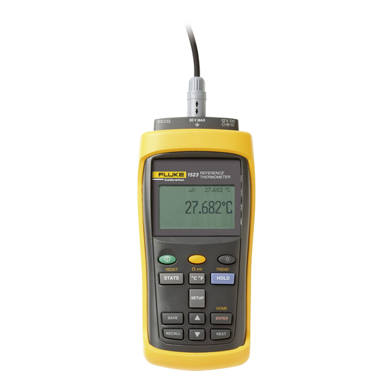
Quick Start Setup 2 Quick Start 2.1 Setup V DC V MAX Figure 3 Input/Output Connections - 1523 Table 2 1523 Input/Output Connections Name Description Serial Serial interface connector Connector, T1 Sensor Connector, Channel 1 Power External Power adapter connection... -
Page 16: Figure 4 Input/Output Connections - 1524
1523, 1524 Reference Thermometer Setup V MAX V DC Figure 4 Input/Output Connections - 1524 Table 3 1524 Input/Output Connections Name Description Serial Serial interface connector Connector, T1 Sensor Connector, Channel 1 Connector, T2 Sensor Connector, Channel 2 Power External Power adapter connection... -
Page 18: Table 4 1523 Key Functions
1523, 1524 Reference Thermometer Setup Table 4 1523 Key Functions Description Power on or off Yellow Second or Special Function Key Turns the backlight on or off 1st Press: MAX, 2nd Press: MIn, 3rd Press: AVE, 4th Press: STD DEV STATS °... -
Page 19: Figure 6 1523 Menu
Quick Start Setup Figure 6 1523 Menu Figure 7 1523 Menu (cont) -
Page 20: Figure 8 1523 Menu (Cont)
Figure 8 1523 Menu (cont) Table 5 1524 Key Functions Description Power on or off Yellow Second or Special Function Key Turns the backlight on or off 1st Press: Max, 2nd Press: Min, 3rd Press: Ave, 4th Press: STD DEV STATS °... - Page 21 Quick Start Setup Description Arrows increment or decrement selections in an active field. In Graph Mode, Arrows change the scale of the graph. ENTER Selects highlighted selection, Saves a new selection. RECALL 1st press - Enters Recall Menu, 2nd press - Exits Recall Menu NEXT Moves down to next option on screen.
-
Page 22: Figure 9 1524 Menu
1523, 1524 Reference Thermometer Setup Figure 9 1524 Menu Figure 10 1524 Menu (cont) -
Page 23: Figure 11 1524 Menu (Cont)
Quick Start Setup Figure 11 1524 Menu (cont) -
Page 24: Figure 12 1524 Menu (Cont)
1523, 1524 Reference Thermometer Setup Figure 12 1524 Menu (cont) -
Page 25: Specifications
Quick Start Specifications Figure 13 1524 Menu (cont) Figure 14 1524 Menu (cont) 2.2 Specifications... -
Page 26: Table 6 General Specifications
1523, 1524 Reference Thermometer Specifications Table 6 General Specifications Operating –10 °C to 60 °C Temperature † 0 °C to 60 °C with ac adapter Storage Temperature –20 °C to 70 °C 10,000 meters above mean sea level Operating altitude... -
Page 27: Table 10 Ohms Measurement, Thermistor
Quick Start Specifications Table 10 Ohms Measurement, Thermistor Ohms Range Accuracy ± Ω, 4 Wire 200 Ω to 50 kΩ ± (0.01 % + 0.5 Ω) 50 kΩ to 500 kΩ ± (0.03 %) Temperature Coefficient ( –10 °C to 13 °C , +33 °C to 60 °C): 0.002 %/°C + 0.1 Ω... -
Page 28: Table 12 Temperature, Thermocouples External Reference Junction
1523, 1524 Reference Thermometer Specifications Table 12 Temperature, Thermocouples External Reference Junction Measure Accuracies Type Range (ITS-90) 600 to 800 °C 0.85 °C 800 to 1000 °C 0.68 °C 1000 to 1800 °C 0.57 °C 100 to 550 °C 0.32 °C 550 to 2300 °C... -
Page 29: Table 13 Temperature, Rtd Ranges And Accuracies (Rtd-90)
Quick Start Specifications Table 13 Temperature, RTD Ranges and Accuracies (RTD-90) Accuracy ± °C 4-wire Probe ± 0.011 at -100 °C ± 0.015 at 0 °C ± 0.019 at 100 °C ± 0.023 at 200 °C ± 0.031 at 400 °C ±... -
Page 30: Table 17 Channel To Channel Differential Specifications
1523, 1524 Reference Thermometer Specifications Table 17 Channel to Channel Differential Specifications Probe Type Times Normal specification T1 – T2 T1 – T2 Fast Scan Mode See Table “Fast Scan Mode Specifications” NOTE: Specification is for T1 – T2 < +/- 10 °C. For Like Probes only. -
Page 31: General Operation
3 General Operation 3.1 Battery When the 1. Power the 1523/24 off and unplug the AC adapter from the unit. 2. Remove the yellow boot. 3. With the 1523/24 facing down, remove the screw and battery cover. 4. Remove the batteries. -
Page 32: Probe
1523, 1524 Reference Thermometer Probe Figure 15 12V DC Power source Polarity Warning: The AC adapter has circuits with high voltages inside that could present danger of electric shock or fire if exposed. If the AC adapter is damaged in any way or becomes hot, discontinue its use immediately, disconnect it from any AC supply, and have it replaced. -
Page 33: Internal Or External Reference Junction Compensation May Be Used With This Instrument
General Operation Probe Lock Function 3.3.1 Internal or External reference junction compensation may be used with this instrument. 3.3.2 TC Internal Reference Junction 3.3.3 TC External Reference Junction Caution: Probes are fragile devices that can be easily damaged by mechanical shock, overheating, and absorption of moisture or fluids in the wires or hub. -
Page 34: Info-Con Connector
1523, 1524 Reference Thermometer INFO-CON Connector 3.5 INFO-CON Connector... -
Page 35: Figure 16 Probe Wiring Diagrams
General Operation INFO-CON Connector Figure 16 Probe wiring diagrams... -
Page 37: Display Functions And User Interface
Display Functions and User Interface HOLD 4 Display Functions and User Interface 4.1 Main Screen 4.2 STATS 4.3 °C °F 4.4 HOLD... -
Page 38: Setup
1523, 1524 Reference Thermometer SETUP 4.5 SETUP 4.5.1 Channel T1 4.5.1.1 Probe 4.5.1.2 Config 4.5.1.3 Base X 4.5.1.4 Aux Displ 4.5.1.4.1 Ohms... -
Page 39: Temp Res
Display Functions and User Interface SETUP 4.5.1.4.2 4.5.1.4.3 RJ Temp 4.5.1.4.4 DeltaX 4.5.1.4.5 T1-T2 4.5.1.4.6 None 4.5.1.5 Temp Res 4.5.1.6 4.5.2 Channel T2 (1524 Only) -
Page 40: Probe
1523, 1524 Reference Thermometer SETUP 4.5.2.1 Probe 4.5.2.2 Config 4.5.2.3 Base X 4.5.2.4 Aux Displ 4.5.2.4.1 Ohms 4.5.2.4.2 T2-T1 4.5.2.4.3 DeltaX... -
Page 41: Temp Res
Display Functions and User Interface SETUP 4.5.2.4.4 None 4.5.2.5 Temp Res 4.5.3 Instrument 4.5.3.1 Fast Scan Mode 4.5.3.2 Contrast 4.5.3.3 Auto-Off 4.5.3.4 Backlight Time 4.5.3.5 Serial Port... -
Page 42: Baud Rate
1523, 1524 Reference Thermometer SAVE 4.5.3.6 Baud Rate 4.5.3.7 Date/Time 4.5.3.7.1 Date 4.5.3.7.2 Time 4.6 SAVE 4.7 ARROWS, UP, DOWN... -
Page 43: Enter
Display Functions and User Interface RECALL 4.8 ENTER 4.9 RECALL 4.9.1 Review Saved 4.9.2 Send Saved 4.9.3 Delete Saved 4.9.4 Send Logs , and Section... -
Page 44: Delete Logs
1523, 1524 Reference Thermometer NEXT 4.9.5 Delete Logs 4.10 NEXT 4.11 SHIFT 4.12 RESET 4.13 Ω mV 4.14 TREND... -
Page 45: Log
Display Functions and User Interface 4.15 LOG 4.15.1 Free 4.15.2 Interval... -
Page 46: Tag
1523, 1524 Reference Thermometer HOME 4.15.3 4.15.4 Session 4.16 HOME... -
Page 47: Logs
LOGS AUTO-LOG 5 LOGS 5.1 DEMAND LOG 5.2 AUTO-LOG 5.2.1 Auto-Log Operation... - Page 48 1523, 1524 Reference Thermometer AUTO-LOG Note: the user specified Tag can only be updated through serial communications through the serial port. Refer to Section 6, Digital Communication Interface on page...
-
Page 49: Sending Auto Log Data To A Computer
LOGS AUTO-LOG Note: If logging with a model 1524 using two active probes and a 1 second interval, a second of data will be skipped approximately every three seconds in order to have unique values in every set of stored data. When the unit is in Auto interval sampling, the Fast Scan Mode Specifications apply. -
Page 51: Digital Communication Interface
Special Note on Using grounded and bare junction thermocouples with RS-232: 1. Use the 1523/24 demand log and auto log functions to avoid connecting to a computer when using grounded junction or bare junction thermocouples. Once the readings are complete, connect the RS-232 cable and upload the data to the personal computer. -
Page 52: Setup
1523, 1524 Reference Thermometer Command Syntax Figure 17 RS-232 wiring 6.1.1 Setup 6.1.2 Serial Operation 6.1.3 Data Upload Format 6.2 Command Syntax... -
Page 53: Serial Commands By Function Or Group
Digital Communication Interface Serial Commands by Function or Group 6.3 Serial Commands by Function or Group... -
Page 54: Table 18 Commands By Function Or Group
1523, 1524 Reference Thermometer Serial Commands by Function or Group Table 18 Commands by Function or Group Password Functions or SCREEN Protection Groups PARAMETER Command Group Read/Write Data Logging - LOG:AUT:DEL <num> Automatic (none) LOG:AUT:FREE? (none) LOG:AUT:LAB? (none) LOG:AUT:LAB <num>... - Page 55 Digital Communication Interface Serial Commands by Function or Group Password Functions or SCREEN Protection Groups PARAMETER Command Group Read/Write Measurement (none) CALC:AVER:CLE (none) CALC<prb>:AVER<n>:DATA? (none) CALC:AVER<n>:TYPE? (none) FETC? <prb> (none) MEAS? <prb> (none) READ? <prb> (none) SENS:DATA:MV? (none) SENS<prb>:DATA:OHMS? (none) SENS:DATA:RJ? SENS:RJ:STAT? (none)
-
Page 56: Serial Commands - Alphabetic Listing
1523, 1524 Reference Thermometer Serial Commands - Alphabetic Listing Password Functions or SCREEN Protection Groups PARAMETER Command Group Read/Write System - BAUD RATE SYST:COMM:SER:BAUD? Communication BAUD RATE SYST:COMM:SER:BAUD <baud> SERIAL PORT SYST:COMM:SER:OFF System - (all) *IDN? Information (none) *CLS (none) - Page 57 Digital Communication Interface Serial Commands - Alphabetic Listing ● ● ● ● ● ● ● ● ● ● ● ● ● ● ● ● ● ● ● ● ● ● *CLS...
- Page 58 1523, 1524 Reference Thermometer Serial Commands - Alphabetic Listing *RST CALCulate:AVERage:CLEar...
- Page 59 Digital Communication Interface Serial Commands - Alphabetic Listing NOTE: This command is protected, which requires a password to set it. NOTE: This command is protected, which requires a password to set it.
- Page 60 1523, 1524 Reference Thermometer Serial Commands - Alphabetic Listing NOTE: This command is protected, which requires a password to set it. CALCulate<prb>:CONVert:SNUMber <seri>...
- Page 61 Digital Communication Interface Serial Commands - Alphabetic Listing NOTE: This command is protected, which requires a password to set it. NOTE: This command is protected, which requires a password to set it.
- Page 62 1523, 1524 Reference Thermometer Serial Commands - Alphabetic Listing CALCulate<prb>:CONVert:VERSion <num> NOTE: This command is protected, which requires a password to set it.
- Page 63 Digital Communication Interface Serial Commands - Alphabetic Listing NOTE: This command is protected, which requires a password to set it.
- Page 64 1523, 1524 Reference Thermometer Serial Commands - Alphabetic Listing NOTE: This command is protected, which requires a password to set it. NOTE: This command is protected, which requires a password to set it.
- Page 65 Digital Communication Interface Serial Commands - Alphabetic Listing NOTE: This command is protected, which requires a password to set it. NOTE: This command is protected, which requires a password to set it.
- Page 66 1523, 1524 Reference Thermometer Serial Commands - Alphabetic Listing...
- Page 67 Digital Communication Interface Serial Commands - Alphabetic Listing...
- Page 68 1523, 1524 Reference Thermometer Serial Commands - Alphabetic Listing...
- Page 69 Digital Communication Interface Serial Commands - Alphabetic Listing...
- Page 70 1523, 1524 Reference Thermometer Serial Commands - Alphabetic Listing...
- Page 71 Digital Communication Interface Serial Commands - Alphabetic Listing...
- Page 72 1523, 1524 Reference Thermometer Serial Commands - Alphabetic Listing...
- Page 73 Digital Communication Interface Serial Commands - Alphabetic Listing...
- Page 74 1523, 1524 Reference Thermometer Serial Commands - Alphabetic Listing...
- Page 75 Digital Communication Interface Serial Commands - Alphabetic Listing...
- Page 76 1523, 1524 Reference Thermometer Serial Commands - Alphabetic Listing bit 0: probe 1 new measurement bits 1 to 7: not used bit 8: probe 2 new measurement bits 9 to 15: not used STATus:MEASure:ENABle <num> bit 0: probe 1 not inserted...
- Page 77 Digital Communication Interface Serial Commands - Alphabetic Listing bit 4: probe 1 locked bits 5 to 7: not used bit 8: probe 2 not inserted bit 9: probe 2 measurement under range bit 10: probe 2 measurement over range bit 11: probe 2 EEPROM fault (bad checksum or version number is not supported) bit 12:...
- Page 78 1523, 1524 Reference Thermometer Serial Commands - Alphabetic Listing SYSTem:COMMunicate:SERial:OFF...
- Page 79 Digital Communication Interface Serial Commands - Alphabetic Listing SYSTem:PASSword:CENable <pass> SYSTem:PASSword:NEW <pass>...
- Page 80 1523, 1524 Reference Thermometer Serial Commands - Alphabetic Listing NOTE: This command is protected, which requires a password to set it.
-
Page 81: Table 19 Statistical Types
Digital Communication Interface Serial Commands - Alphabetic Listing UNIT:TEMPerature <unit> Table 19 Statistical Types Number Type Keyword Maximum Minimum Average Standard Deviation Delta X Delta T Table 20 Probe Conversion Types Probe Conversion Keyword ITS90 ITS90-5 ITS5 PT100 RPRT Resistance TRES Thermistor Polynominal R(T) -
Page 82: Table 21 Probe Characterization Parameters
1523, 1524 Reference Thermometer Serial Commands - Alphabetic Listing Probe Conversion Keyword Thermocouple Millivolts Table 21 Probe Characterization Parameters Conversion Keyword Value ITS90 RTPW Double Floating Point Double Floating Point Double Floating Point Double Floating Point Double Floating Point Double Floating Point... -
Page 83: Table 22 Calibration Range Identifiers
Digital Communication Interface Serial Commands - Alphabetic Listing Conversion Keyword Value PT100 Double Floating Point MINOP Integer, °C MAXOP Integer, °C Resistance MINOP Integer, Ω MAXOP Integer, Ω Polynomial R(T) Double Floating Point Double Floating Point Double Floating Point Double Floating Point MINOP Integer, °C MAXOP... -
Page 84: Table 23 Demand Log Statistical Types
1523, 1524 Reference Thermometer Serial Commands - Alphabetic Listing Table 23 Demand Log Statistical Types Number Type Maximum Minimum Average Standard Deviation Auxiliary Value For all For all Table 24 Error Messages Number Message "No error" -100 "Command error" -200 "Execution error"... -
Page 85: Calibration Of Your Reference Thermometer Readout
Calibration of Your Reference Thermometer Readout Calibration Equipment 7 Calibration of Your Reference Thermometer Readout 7.1 General NOTE: For assistance with the process or any questions regarding the calibration of the Reference Thermometer, contact an Authorized Service Center. (See Section 1.8, Authorized Service Centers on page 5.) 7.2 Introduction 7.3 Terminology... -
Page 86: Manual Calibration
1523, 1524 Reference Thermometer Manual Calibration Table 25 Test Equipment Specifications Classification Minimum Use Recommended Equipment Voltage Source ± 6ppm ± 0.6uV Fluke 5700 4 wire Reference Resistors See Total Uncertainty column Vishay VHP100 Resistors Table X 4 wire cable... -
Page 87: Figure 18 Flow Chart For Manual Calibration
Calibration of Your Reference Thermometer Readout Manual Calibration Prepare Test Equipment Visual Inspection As-Found Need As- Data Found data? Parameters Set Reference As-Found Test Points and Reset Data Adj Values Take Alignment Data Calculate New Adj Values As Left Accuracy Data Finished Figure 18... -
Page 88: As Found Data Procedure
1523, 1524 Reference Thermometer Preparation for Reference Thermometer Calibration 7.7.2 As Found Data Procedure 7.7.2.1 As Found Calibration Parameters 7.7.2.2 As Found Data 7.7.3 Alignment Procedure 7.7.3.1 Alignment Test Data 7.7.3.2 Calculate New Adjustment Values 7.7.4 As Left Data 7.8 Preparation for Reference Thermometer Calibration 7.8.1... -
Page 89: Cabling
AC Adapter 7.9 Manual Calibration Process NOTE: 1. The 1523/24 is tested and calibrated using the tests outlined below in the order indicated. Details on performing each of the tests can be found in the subsequent section of this document. -
Page 90: Procedure
Procedure 7.9.1.1 Visual Inspection 7.9.1.2 1523/24 Calibration Parameters (As Found) NOTE: If not taking As Found data, skip to the 1523/24 alignment section. Table 30 As Found Readout/Calibration Parameter Settings Parameter Description # of Cal Ref Points Each Cal Range has 1 to 4 Ref Cal Points... - Page 91 Calibration of Your Reference Thermometer Readout Manual Calibration Process 2. Set the UUT password enable by sending the following commands through the serial port: 3. Set the UUT to the L75_OHMS cal range by sending the following commands through the serial port: 4.
-
Page 92: 1523/24 Accuracy Test (As Found)
17. Query the ADJ values for the range by sending the following Command: 18. Record the as found alignment parameters. 7.9.1.3 1523/24 Accuracy Test (As Found) 19. Connect the calibration cable, described in the Preparation and Settings for Reference readout Calibration section, to Channel T1 of the UUT. Using a... - Page 93 37. Query the reading every 2 seconds for 40 readings using the following command: Note: Steps 38 through 42 apply to the 1524 only. Proceed to step 43 if using a 1523. 38. (1524 ONLY) Set Channel T2 of the UUT in the LO_OHMS cal range by...
- Page 94 50. Connect a 40K Ohm resistor to the calibration cable connected to the UUT. 51. Query the reading every 2 seconds for 40 readings using the following command: Note: Steps 52 through 56 apply to the 1524 only. Proceed to step 57 if using a 1523.
- Page 95 Calibration of Your Reference Thermometer Readout Manual Calibration Process 52. (1524 ONLY) Set Channel T2 of the UUT in the MED_OHMS cal range by sending the following commands through the serial port: 53. Turn off T1 by sending the following command. 54.
- Page 96 1523, 1524 Reference Thermometer Manual Calibration Process Note: Steps 66 through 70 apply to the 1524 only. Proceed to step 71 if using a 1523. 66. (1524 ONLY) Set Channel T2 of the UUT in the HI_OHMS cal range by sending the following commands through the serial port: 67.
-
Page 97: 1523/24 Alignment
Accuracy limit listed in the Accuracy Test Settings and Specification tables. 7.9.2 1523/24 Alignment Caution: Failure to do this will cause large errors in the measurement readings and invalidate the calibration. Table 31 1523/24 Alignment Settings Setting Cal Range Value Description... - Page 98 2. Set the number of Ref points to 2 for each range by sending the following serial commands. 3. Set all Reference points to their designated values (see Table 31 on previous page, 1523/24 Alignment settings) for each range by sending the following commands:...
- Page 99 Calibration of Your Reference Thermometer Readout Manual Calibration Process 4. Set all adjustment parameters to 0.0 for each range by sending the following commands: 5. Take alignment data by following (or repeating) the steps in the As Found Data section. Do not take alignment data for Channel T2. 6.
-
Page 100: L75_Ohms Range
1523, 1524 Reference Thermometer Manual Calibration Process 7.9.2.1 L75_OHMS Range 7.9.2.2 LO_OHMS Range 7.9.2.3 MED_OHMS Range 7.9.2.4 HI_OHMS Range 7.9.2.5 Millivolt Range 8. Send the calculated ADJ values from step 7 to the UUT using the following serial commands. The XXXX represents the new calculated value. -
Page 101: 1523/24 As Left Test Data
Calibration of Your Reference Thermometer Readout Manual Calibration Process 7.9.3 1523/24 As Left Test Data 1. Take as Left data by following the steps in the As Found Data section. 2. Calculate the average and the standard deviation of the measurements taken in step 1, including the Channel T2 data. -
Page 103: Troubleshooting
Troubleshooting 8 Troubleshooting Problem Solution The battery is low and needs to be changed. When this symbol appears, “Battery Symbol” is displayed the batteries should be replaced to ensure the accuracy of readings. The instrument is unable to detect that a probe is connected. Check that a “Waiting for Data”... -
Page 105: Maintenance
Maintenance 9 Maintenance Note: Use only AA alkaline batteries. -
Page 107: Index
Index Symbols... - Page 108 1529 Chub-E4 Thermometer Readout...
Need help?
Do you have a question about the 1523 and is the answer not in the manual?
Questions and answers