Sign In
Upload
Manuals
Brands
Fluke Manuals
Thermometer
Hart Scientific 1523
Fluke Hart Scientific 1523 Manuals
Manuals and User Guides for Fluke Hart Scientific 1523. We have
5
Fluke Hart Scientific 1523 manuals available for free PDF download: Technical Manual, User Manual
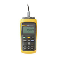
Fluke Hart Scientific 1523 Technical Manual (110 pages)
Reference Thermometer
Brand:
Fluke
| Category:
Thermometer
| Size: 5 MB
Table of Contents
Table of Contents
3
1 Before You Start
9
Introduction
9
Standard Equipment
9
Safety Information
9
Warning
9
Cautions
10
CE Comments
11
EMC Directive
11
Immunity Testing
11
For Use as a Portable (Hand-Held) Instrument
11
Table 1 International Symbols
11
For Use as a Benchtop Instrument (AC Adapter)
12
Locking out Non si Units
12
Using Clamp-On Ferrites
12
Figure 1 Locking out Non si Units
12
Emissions Testing
13
Low Voltage Directive (Safety)
13
Authorized Service Centers
13
Figure 2 Clamp-On Ferrite
13
2 Quick Start
15
Setup
15
Figure 3 Input/Output Connections - 1523
15
Table 2 1523 Input/Output Connections
15
Figure 4 Input/Output Connections - 1524
16
Table 3 1524 Input/Output Connections
16
Figure 5 Keys
17
Table 4 1523 Key Functions
18
Figure 6 1523 Menu
19
Figure 7 1523 Menu (Cont)
19
Figure 8 1523 Menu (Cont)
20
Table 5 1524 Key Functions
20
Figure 9 1524 Menu
22
Figure 10 1524 Menu (Cont)
22
Figure 11 1524 Menu (Cont)
23
Figure 12 1524 Menu (Cont)
24
Specifications
25
Figure 13 1524 Menu (Cont)
25
Figure 14 1524 Menu (Cont)
25
Table 6 General Specifications
26
Table 7 Millivolt Measurement
26
Table 8 Reference Junction Compensation
26
Table 9 Ohms Measurement, Rtds
26
Table 10 Ohms Measurement, Thermistor
27
Table 11 Equivalent Temperature Accuracies Derived from Primary Specifications (Ω, MV)
27
Table 12 Temperature, Thermocouples External Reference Junction
28
Table 13 Temperature, RTD Ranges and Accuracies (RTD-90)
29
Table 14 Temperature, Thermistor
29
Table 15 Fast Scan Mode Specifications
29
Table 16 Sample Interval Per Channel in Seconds
29
Table 17 Channel to Channel Differential Specifications
30
3 General Operation
31
Battery
31
DC Power Source
31
Probe
32
Figure 15 12V DC Power Source Polarity
32
Internal or External Reference Junction Compensation May be Used with this Instrument
33
TC External Reference Junction
33
TC Internal Reference Junction
33
Probe Lock Function
33
INFO-CON Connector
34
Figure 16 Probe Wiring Diagrams
35
4 Display Functions and User Interface
37
Main Screen
37
Stats
37
Hold
37
Setup
38
Channel T1
38
Probe
38
Config
38
Base X
38
Aux Displ
38
Temp Res
39
Channel T2 (1524 Only)
39
Probe
40
Config
40
Base X
40
Aux Displ
40
Temp Res
41
Instrument
41
Fast Scan Mode
41
Contrast
41
Auto-Off
41
Backlight Time
41
Serial Port
41
Baud Rate
42
Date/Time
42
Save
42
Arrows, Up, down
42
Enter
43
Recall
43
Review Saved
43
Send Saved
43
Delete Saved
43
Send Logs
43
Delete Logs
44
Next
44
Shift
44
Reset
44
Ω MV
44
Trend
44
Log
45
Free
45
Interval
45
Tag
46
Session
46
Home
46
5 Logs
47
Demand Log
47
Auto-Log
47
Auto-Log Operation
47
Sending Auto Log Data to a Computer
49
Data Upload Format
49
Deleting Auto Log Data
49
6 Digital Communication Interface
51
Wiring
51
Setup
52
Serial Operation
52
Data Upload Format
52
Command Syntax
52
Figure 17 RS-232 Wiring
52
Serial Commands by Function or Group
53
Table 18 Commands by Function or Group
54
Serial Commands - Alphabetic Listing
56
Table 19 Statistical Types
81
Table 20 Probe Conversion Types
81
Table 21 Probe Characterization Parameters
82
Table 22 Calibration Range Identifiers
83
Table 23 Demand Log Statistical Types
84
Table 24 Error Messages
84
7 Calibration of Your Reference Thermometer Readout
85
General
85
Introduction
85
Terminology
85
Fundamentals
85
Environmental Test Conditions
85
Calibration Equipment
85
Manual Calibration
86
General
86
Table 25 Test Equipment Specifications
86
Table 26 Standard Reference Resistor Specification
86
Table 27 Standard Voltage Reference Specification
86
Figure 18 Flow Chart for Manual Calibration
87
As Found Data Procedure
88
As Found Calibration Parameters
88
As Found Data
88
Alignment Procedure
88
Alignment Test Data
88
Calculate New Adjustment Values
88
As Left Data
88
Preparation for Reference Thermometer Calibration
88
Serial Communication
88
Cabling
89
Scan Mode
89
AC Adapter
89
Manual Calibration Process
89
Table 28 1523/24 Accuracy Test Settings and Specifications
89
Procedure
90
Visual Inspection
90
1523/24 Calibration Parameters (as Found)
90
Table 29 1523/24 Accuracy Test Settings and Specifications - Voltage
90
Table 30 as Found Readout/Calibration Parameter Settings
90
1523/24 Accuracy Test (as Found)
92
1523/24 Alignment
97
Table 31 1523/24 Alignment Settings
97
HI_OHMS Range
100
L75_OHMS Range
100
LO_OHMS Range
100
MED_OHMS Range
100
Millivolt Range
100
1523/24 as Left Test Data
101
8 Troubleshooting
103
9 Maintenance
105
Index
107
Advertisement
Fluke Hart Scientific 1523 Technical Manual (104 pages)
Reference Thermometer
Brand:
Fluke
| Category:
Thermometer
| Size: 5 MB
Table of Contents
Table of Contents
3
Before You Start
9
Introduction
9
Standard Equipment
9
Safety Information
9
Warning
9
Cautions
10
CE Comments
11
EMC Directive
11
Immunity Testing
11
For Use as a Portable (Hand-Held) Instrument
11
Table 1 International Symbols
11
For Use as a Benchtop Instrument (AC Adapter)
12
Locking out Non si Units
12
Using Clamp-On Ferrites
12
Figure 1 Locking out Non si Units
12
Emissions Testing
13
Low Voltage Directive (Safety)
13
Authorized Service Centers
13
Figure 2 Clamp-On Ferrite
13
Quick Start
14
Setup
14
Table 2 1523 Input/Output Connections
14
Figure 4 Input/Output Connections - 1524
15
Table 3 1524 Input/Output Connections
15
Table 4 1523 Key Functions
17
Figure 6 1523 Menu
18
Figure 7 1523 Menu (Cont)
18
Figure 8 1523 Menu (Cont)
19
Table 5 1524 Key Functions
19
Figure 9 1524 Menu
21
Figure 10 1524 Menu (Cont)
21
Figure 11 1524 Menu (Cont)
22
Figure 12 1524 Menu (Cont)
23
Specifications
24
Figure 13 1524 Menu (Cont)
24
Figure 14 1524 Menu (Cont)
24
Table 6 General Specifications
25
Table 7 Millivolt Measurement
25
Table 8 Reference Junction Compensation
25
Table 9 Ohms Measurement, Rtds
25
Table 10 Ohms Measurement, Thermistor
26
Table 11 Equivalent Temperature Accuracies Derived from Primary Specifications (Ω, MV)
26
Table 12 Temperature, Thermocouples External Reference Junction
27
Table 13 Temperature, RTD Ranges and Accuracies (RTD-90)
28
Table 14 Temperature, Thermistor
28
Table 15 Fast Scan Mode Specifications
28
Table 16 Sample Interval Per Channel in Seconds
28
Table 17 Channel to Channel Differential Specifications
29
General Operation
30
Battery
30
DC Power Source
30
Probe
31
Figure 15 12V DC Power Source Polarity
31
Internal or External Reference Junction Compensation May be Used with this Instrument
32
TC Internal Reference Junction
32
TC External Reference Junction
32
Probe Lock Function
32
INFO-CON Connector
33
Figure 16 Probe Wiring Diagrams
34
Display Functions and User Interface
35
Main Screen
35
Stats
35
Hold
35
Setup
36
Channel T1
36
Probe
36
Config
36
Base X
36
Aux Displ
36
Temp Res
37
Channel T2 (1524 Only)
37
Probe
38
Config
38
Base X
38
Aux Displ
38
Temp Res
39
Instrument
39
Fast Scan Mode
39
Contrast
39
Auto-Off
39
Backlight Time
39
Serial Port
39
Baud Rate
40
Date/Time
40
Save
40
Arrows, Up, down
40
Enter
41
Recall
41
Review Saved
41
Send Saved
41
Delete Saved
41
Send Logs
41
Delete Logs
42
Next
42
Shift
42
Reset
42
Ω MV
42
Trend
42
Log
43
Free
43
Interval
43
Tag
44
Session
44
Home
44
Logs
45
Demand Log
45
Auto-Log
45
Auto-Log Operation
45
Sending Auto Log Data to a Computer
47
Data Upload Format
47
Deleting Auto Log Data
47
Digital Communication Interface
48
Wiring
48
Setup
49
Serial Operation
49
Data Upload Format
49
Command Syntax
49
Figure 17 RS-232 Wiring
49
Serial Commands by Function or Group
50
Table 18 Commands by Function or Group
51
Serial Commands - Alphabetic Listing
53
Table 19 Statistical Types
78
Table 20 Probe Conversion Types
78
Table 21 Probe Characterization Parameters
79
Table 22 Calibration Range Identifiers
80
Table 23 Demand Log Statistical Types
81
Table 24 Error Messages
81
Calibration of Your Reference Thermometer Readout
82
General
82
Introduction
82
Terminology
82
Fundamentals
82
Environmental Test Conditions
82
Calibration Equipment
82
Manual Calibration
83
General
83
Table 25 Test Equipment Specifications
83
Table 26 Standard Reference Resistor Specification
83
Table 27 Standard Voltage Reference Specification
83
Figure 18 Flow Chart for Manual Calibration
84
As Found Data Procedure
85
As Found Calibration Parameters
85
As Found Data
85
Alignment Procedure
85
Alignment Test Data
85
Calculate New Adjustment Values
85
As Left Data
85
Preparation for Reference Thermometer Calibration
85
Serial Communication
85
Cabling
86
Scan Mode
86
AC Adapter
86
Manual Calibration Process
86
Table 28 1523/24 Accuracy Test Settings and Specifications
86
Procedure
87
Visual Inspection
87
1523/24 Calibration Parameters (as Found)
87
Table 29 1523/24 Accuracy Test Settings and Specifications - Voltage
87
Table 30 as Found Readout/Calibration Parameter Settings
87
1523/24 Accuracy Test (as Found)
89
1523/24 Alignment
94
Table 31 1523/24 Alignment Settings
94
L75_OHMS Range
97
LO_OHMS Range
97
MED_OHMS Range
97
HI_OHMS Range
97
Millivolt Range
97
1523/24 as Left Test Data
98
Troubleshooting
99
Maintenance
100
Index
101
Fluke Hart Scientific 1523 Technical Manual (104 pages)
Reference Thermometer
Brand:
Fluke
| Category:
Thermometer
| Size: 5 MB
Table of Contents
Table of Contents
3
Before You Start
9
Introduction
9
Standard Equipment
9
Safety Information
9
Warning
9
Cautions
10
CE Comments
11
EMC Directive
11
Immunity Testing
11
For Use as a Portable (Hand-Held) Instrument
11
Table 1 International Symbols
11
For Use as a Benchtop Instrument (AC Adapter)
12
Locking out Non si Units
12
Using Clamp-On Ferrites
12
Figure 1 Locking out Non si Units
12
Emissions Testing
13
Low Voltage Directive (Safety)
13
Authorized Service Centers
13
Figure 2 Clamp-On Ferrite
13
Quick Start
14
Setup
14
Figure 3 Input/Output Connections - 1523
14
Table 2 1523 Input/Output Connections
14
Figure 4 Input/Output Connections - 1524
15
Table 3 1524 Input/Output Connections
15
Table 4 1523 Key Functions
17
Figure 6 1523 Menu
18
Figure 7 1523 Menu (Cont)
18
Figure 8 1523 Menu (Cont)
19
Table 5 1524 Key Functions
19
Figure 9 1524 Menu
21
Figure 10 1524 Menu (Cont)
21
Figure 11 1524 Menu (Cont)
22
Figure 12 1524 Menu (Cont)
23
Specifications
24
Figure 13 1524 Menu (Cont)
24
Figure 14 1524 Menu (Cont)
24
Table 6 General Specifications
25
Table 7 Millivolt Measurement
25
Table 8 Reference Junction Compensation
25
Table 9 Ohms Measurement, Rtds
25
Table 10 Ohms Measurement, Thermistor
26
Table 11 Equivalent Temperature Accuracies Derived from Primary Specifications (Ω, MV)
26
Table 12 Temperature, Thermocouples External Reference Junction
27
Table 13 Temperature, RTD Ranges and Accuracies (RTD-90)
28
Table 14 Temperature, Thermistor
28
Table 15 Fast Scan Mode Specifications
28
Table 16 Sample Interval Per Channel in Seconds
28
Table 17 Channel to Channel Differential Specifications
29
General Operation
30
Battery
30
DC Power Source
30
Probe
31
Figure 15 12V DC Power Source Polarity
31
Internal or External Reference Junction Compensation May be Used with this Instrument
32
TC Internal Reference Junction
32
TC External Reference Junction
32
Probe Lock Function
32
INFO-CON Connector
33
Figure 16 Probe Wiring Diagrams
34
Display Functions and User Interface
35
Main Screen
35
Stats
35
Hold
35
Setup
36
Channel T1
36
Probe
36
Config
36
Aux Displ
36
Temp Res
37
Channel T2 (1524 Only)
37
Probe
38
Config
38
Aux Displ
38
Temp Res
39
Instrument
39
Fast Scan Mode
39
Contrast
39
Auto-Off
39
Backlight Time
39
Serial Port
39
Baud Rate
40
Date/Time
40
Save
40
Arrows, Up, down
40
Enter
41
Recall
41
Review Saved
41
Send Saved
41
Delete Saved
41
Send Logs
41
Delete Logs
42
Next
42
Shift
42
Reset
42
Ω MV
42
Trend
42
Log
43
Free
43
Interval
43
Tag
44
Session
44
Home
44
Logs
45
Demand Log
45
Auto-Log
45
Auto-Log Operation
45
Sending Auto Log Data to a Computer
47
Data Upload Format
47
Deleting Auto Log Data
47
Digital Communication Interface
48
Wiring
48
Setup
49
Serial Operation
49
Data Upload Format
49
Command Syntax
49
Figure 17 RS-232 Wiring
49
Serial Commands by Function or Group
50
Table 18 Commands by Function or Group
51
Serial Commands - Alphabetic Listing
53
Table 19 Statistical Types
78
Table 20 Probe Conversion Types
78
Table 21 Probe Characterization Parameters
79
Table 22 Calibration Range Identifiers
80
Table 23 Demand Log Statistical Types
81
Table 24 Error Messages
81
Calibration of Your Reference Thermometer Readout
82
General
82
Introduction
82
Terminology
82
Fundamentals
82
Environmental Test Conditions
82
Calibration Equipment
82
Manual Calibration
83
General
83
Table 25 Test Equipment Specifications
83
Table 26 Standard Reference Resistor Specification
83
Table 27 Standard Voltage Reference Specification
83
Figure 18 Flow Chart for Manual Calibration
84
As Found Data Procedure
85
As Found Calibration Parameters
85
As Found Data
85
Alignment Procedure
85
Alignment Test Data
85
Calculate New Adjustment Values
85
As Left Data
85
Preparation for Reference Thermometer Calibration
85
Serial Communication
85
Cabling
86
Scan Mode
86
AC Adapter
86
Manual Calibration Process
86
Table 28 1523/24 Accuracy Test Settings and Specifications
86
Procedure
87
Visual Inspection
87
1523/24 Calibration Parameters (as Found)
87
Table 29 1523/24 Accuracy Test Settings and Specifications - Voltage
87
Table 30 as Found Readout/Calibration Parameter Settings
87
1523/24 Accuracy Test (as Found)
89
1523/24 Alignment
94
Table 31 1523/24 Alignment Settings
94
L75_OHMS Range
97
LO_OHMS Range
97
MED_OHMS Range
97
HI_OHMS Range
97
Millivolt Range
97
1523/24 as Left Test Data
98
Troubleshooting
99
Maintenance
100
Index
101
Advertisement
Fluke Hart Scientific 1523 Technical Manual (105 pages)
reference thermometer
Brand:
Fluke
| Category:
Thermometer
| Size: 4 MB
Table of Contents
Table of Contents
3
1 Before You Start
9
Introduction
9
Standard Equipment
9
Safety Information
9
Warning
9
Cautions
10
CE Comments
11
EMC Directive
11
Immunity Testing
11
For Use as a Portable (Hand-Held) Instrument
11
Table 1 International Symbols
11
For Use as a Benchtop Instrument (AC Adapter)
12
Locking out Non si Units
12
Using Clamp-On Ferrites
12
Figure 1 Locking out Non si Units
12
Emissions Testing
13
Low Voltage Directive (Safety)
13
Authorized Service Centers
13
Figure 2 Clamp-On Ferrite
13
2 Quick Start
14
Setup
14
Figure 3 Input/Output Connections - 1523
14
Table 2 1523 Input/Output Connections
14
Figure 4 Input/Output Connections - 1524
15
Table 3 1524 Input/Output Connections
15
Figure 5 Keys
16
Table 4 1523 Key Functions
17
Figure 6 1523 Menu
18
Figure 7 1523 Menu (Cont)
18
Figure 8 1523 Menu (Cont)
19
Table 5 1524 Key Functions
19
Figure 9 1524 Menu
21
Figure 10 1524 Menu (Cont)
21
Figure 11 1524 Menu (Cont)
22
Figure 12 1524 Menu (Cont)
23
Specifications
24
Figure 13 1524 Menu (Cont)
24
Figure 14 1524 Menu (Cont)
24
Table 6 General Specifications
25
Table 7 Millivolt Measurement
25
Table 8 Reference Junction Compensation
25
Table 9 Ohms Measurement, Rtds
25
Table 10 Ohms Measurement, Thermistor
26
Table 11 Equivalent Temperature Accuracies Derived from Primary Specifications (Ω, MV)
26
Table 12 Temperature, Thermocouples External Reference Junction
27
Table 13 Temperature, RTD Ranges
28
And Accuracies (RTD-90)
28
Table 14 Temperature, Thermistor
28
Table 15 Fast Scan Mode Specifications
28
Table 16 Sample Interval Per Channel in Seconds
28
Table 17 Channel to Channel Differential Specifications
29
3 General Operation
30
Battery
30
DC Power Source
30
Probe
31
Figure 15 12V DC Power Source Polarity
31
Internal or External Reference Junction Compensation May be Used with this Instrument
32
TC External Reference Junction
32
TC Internal Reference Junction
32
Probe Lock Function
32
INFO-CON Connector
33
Figure 16 Probe Wiring Diagrams
34
4 Display Functions and User Interface
36
Main Screen
36
Stats
36
Hold
36
Setup
37
Channel T1
37
Probe
37
Config
37
Base X
37
Aux Displ
37
Temp Res
38
Channel T2 (1524 Only)
38
Probe
39
Config
39
Base X
39
Aux Displ
39
Temp Res
40
Instrument
40
Fast Scan Mode
40
Contrast
40
Auto-Off
40
Backlight Time
40
Serial Port
40
Baud Rate
41
Date/Time
41
Save
41
Arrows, Up, down
41
Enter
42
Recall
42
Review Saved
42
Send Saved
42
Delete Saved
42
Send Logs
42
Delete Logs
43
Next
43
Shift
43
Reset
43
Ω MV
43
Trend
43
Log
44
Free
44
Interval
44
Tag
45
Session
45
Home
45
5 Logs
46
Demand Log
46
Auto-Log
46
Auto-Log Operation
46
Sending Auto Log Data to a Computer
48
Data Upload Format
48
Deleting Auto Log Data
48
6 Digital Communication Interface
50
Wiring
50
Setup
51
Serial Operation
51
Data Upload Format
51
Command Syntax
51
Figure 17 RS-232 Wiring
51
Serial Commands by Function or Group
52
Table 18 Commands by Function or Group
53
Serial Commands - Alphabetic Listing
55
Table 19 Statistical Types
80
Table 20 Probe Conversion Types
80
Table 21 Probe Characterization Parameters
81
Table 22 Calibration Range Identifiers
82
Table 23 Demand Log Statistical Types
83
Table 24 Error Messages
83
7 Calibration of Your Reference Thermometer Readout
84
General
84
Introduction
84
Terminology
84
Fundamentals
84
Environmental Test Conditions
84
Calibration Equipment
84
Manual Calibration
85
General
85
Table 25 Test Equipment Specifications
85
Table 26 Standard Reference Resistor Specification
85
Table 27 Standard Voltage Reference Specification
85
Figure 18 Flow Chart for Manual Calibration
86
As Found Data Procedure
87
As Found Calibration Parameters
87
As Found Data
87
Alignment Procedure
87
Alignment Test Data
87
Calculate New Adjustment Values
87
As Left Data
87
Preparation for Reference Thermometer Calibration
87
Serial Communication
87
Cabling
88
Table 28 1523/24 Accuracy Test Settings and Specifications
88
Table 29 1523/24 Accuracy Test Settings and Specifications - Voltage
89
Table 30 as Found Readout/Calibration Parameter Settings
89
Procedure
89
Accuracy Test (as Found)
91
Table 31 1523/24 Alignment Settings
96
Alignment
96
L75_OHMS Range
99
As Left Test Data
100
8 Troubleshooting
101
9 Maintenance
104
Fluke Hart Scientific 1523 User Manual (36 pages)
Thermometer Readout
Brand:
Fluke
| Category:
Thermometer
| Size: 3 MB
Table of Contents
Limited Warranty and Limitation of Liability
3
Table of Contents
5
Table of Contents
9
1 Before You Start
9
Introduction
9
Standard Equipment
9
Safety Information
10
Warning
10
Cautions
11
Table 1 International Symbols
12
Tables
12
CE Comments
13
EMC Directive
13
Immunity Testing
13
Using Clamp-On Ferrites
13
Emissions Testing
14
Low Voltage Directive (Safety)
14
Figure 1 Clamp-On Ferrite
14
1.8 Authorized Service Centers
15
2 Quick Start
17
Setup
17
Figure 2 Input/Output Connections - 1523
17
Table 2 1523 Input/Output Connections
17
Figure 3 Input/Output Connections - 1524
18
Table 3 1524 Input/Output Connections
18
Figure 4 Keys
19
Table 4 1523 Key Functions
20
Figure 5 1523 Menu
22
Figure 6 1523 Menu (Cont)
23
Figure 7 1523 Menu (Cont)
24
Table 5 1524 Key Functions
25
Figure 8 1524 Menu
27
Figure 9 1524 Menu (Cont)
28
Figure 10 1524 Menu (Cont)
29
Figure 11 1524 Menu (Cont)
30
Figure 12 1524 Menu (Cont)
31
Specifications
32
Figure 13 1524 Menu (Cont)
32
Table 6 General Specifications
32
Table 7 Millivolt Measurement
33
Table 8 Ohms Measurement, Rtds
33
Table 9 Ohms Measurement, Thermistor
34
Table 10 Temperature, Thermocouples
34
Table 11 Temperature, RTD Ranges, and Accuracies (ITS-90)
36
Table 12 Temperature, Thermistor
36
Advertisement
Related Products
Fluke Hart Scientific 1524
Fluke Hart Scientific 1522
Fluke 1521
Fluke 1529 Chub-E4
Fluke 1529
Fluke 1523-P4-256
Fluke 1524-P4-256
Fluke 1595A
Fluke 1502A
Fluke Hart Scientific 1590 Super-Thermometer II
Fluke Categories
Measuring Instruments
Test Equipment
Multimeter
Thermometer
Laboratory Equipment
More Fluke Manuals
Login
Sign In
OR
Sign in with Facebook
Sign in with Google
Upload manual
Upload from disk
Upload from URL